EP1124290A2 - Connecteur électrique - Google Patents
Connecteur électrique Download PDFInfo
- Publication number
- EP1124290A2 EP1124290A2 EP01102515A EP01102515A EP1124290A2 EP 1124290 A2 EP1124290 A2 EP 1124290A2 EP 01102515 A EP01102515 A EP 01102515A EP 01102515 A EP01102515 A EP 01102515A EP 1124290 A2 EP1124290 A2 EP 1124290A2
- Authority
- EP
- European Patent Office
- Prior art keywords
- sections
- contact
- connector
- electrical connector
- contact elements
- Prior art date
- Legal status (The legal status is an assumption and is not a legal conclusion. Google has not performed a legal analysis and makes no representation as to the accuracy of the status listed.)
- Withdrawn
Links
Images

Classifications
-
- H—ELECTRICITY
- H01—ELECTRIC ELEMENTS
- H01R—ELECTRICALLY-CONDUCTIVE CONNECTIONS; STRUCTURAL ASSOCIATIONS OF A PLURALITY OF MUTUALLY-INSULATED ELECTRICAL CONNECTING ELEMENTS; COUPLING DEVICES; CURRENT COLLECTORS
- H01R13/00—Details of coupling devices of the kinds covered by groups H01R12/70 or H01R24/00 - H01R33/00
- H01R13/62—Means for facilitating engagement or disengagement of coupling parts or for holding them in engagement
- H01R13/627—Snap or like fastening
- H01R13/6271—Latching means integral with the housing
- H01R13/6272—Latching means integral with the housing comprising a single latching arm
-
- H—ELECTRICITY
- H01—ELECTRIC ELEMENTS
- H01R—ELECTRICALLY-CONDUCTIVE CONNECTIONS; STRUCTURAL ASSOCIATIONS OF A PLURALITY OF MUTUALLY-INSULATED ELECTRICAL CONNECTING ELEMENTS; COUPLING DEVICES; CURRENT COLLECTORS
- H01R13/00—Details of coupling devices of the kinds covered by groups H01R12/70 or H01R24/00 - H01R33/00
- H01R13/648—Protective earth or shield arrangements on coupling devices, e.g. anti-static shielding
- H01R13/658—High frequency shielding arrangements, e.g. against EMI [Electro-Magnetic Interference] or EMP [Electro-Magnetic Pulse]
- H01R13/6581—Shield structure
- H01R13/6582—Shield structure with resilient means for engaging mating connector
Definitions
- the present invention relates to electrical connectors and, particularly, to an electrical connector having a plurality of contact elements with contact sections arranged laterally.
- An electrical connector of this type is disclosed in Japanese patent application Kokai No. 11-505663.
- This connector comprises a housing with a plug section for plugging with a mating connector and a plurality of contact. elements with contact sections arranged on Lhe front face of the plug section in the widthwise direction of the connector. A pair of lock arms arc provided upper and lower sides of the contact sections for supporting the mating connector. It is frequent that the mating connector is attached to a circuit board so that it. is desired that the height of the connector be small.
- the above connector has the lock members on both the upper and lower sides of the contact sections, increasing the height of the connector.
- the distance between the two lock members is so small that it hardly controls the tilting of the connector when it is plugged with an excessive force.
- an object of the invention to provide an electrical connector that is of low profile yet capable of controlling the tilting of the connector upon forced plugging.
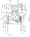
- a connector 40 is mounted on a circuit board P, and another connector 10 is plugged into the connector 40.
- the width of each of the connectors 10 and 40 (in a first direction parallel to the circuit board P and perpendicular to the plugging direction) is made greater than the height thereof (in a second direction perpendicular to the circuit board P).
- the connector 10 has a connector body 11 and a cover member 31 for accommodating the connector body 11.
- the connector body 11 comprises a housing body 13 with a plurality of elongated inner cavities 12 provided in the first direction, a plurality of contact elements 14 put in the inner cavities 12, respectively, and a pair of shield plates 15 and 16 provided on the upper and lower surfaces of the housing body 13, respectively.
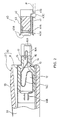
- Each inner cavity 12 is enlarged in the second direction for accommodating one of the contact elements 14.
- the width and height of the plug section 17 are made smaller than those of the housing body 13 so that the inner cavities 12 are made smaller in the second direction in the plug section 17 than in the housing body 13 (Fig. 2).
- a pair of protruded sections 18 extend forwardly from the pluq section 17 to not only form a recess 19 therebetween but also guide plugging with the mating connector 40.
- a pair of fine grooves 20 are provided on the upper faces of the protruded sections 18 for receiving lock members 21.
- Each lock member 21 is made substantially flat and has an engaging claw 21A projecting from the upper face of the protruded section 18 (Fig. 3). The engaging claws 21A of Lhe lock members 21 are depressed into the fine grooves 20 by a flexible pressure section 33 that is made by a pair of slits 32 cut in the cover member 31.
- the lower shield plate 16 is made thicker than the upper shield plate 15 for providing strength.
- the shield plate 16 is provided with a protective section 16A made of a metal sheet covering the outer and front sides of the protruded sections 18.
- Each contact element 14 has a U-shaped front contact section 14A, a connection section 14B projecting rearwardly from the housing body 13, and an S-shaped flexible section 14C between them.
- the contact elements 14 include long ground contact elements 14' and short signal contact elements 14".
- the contact sections 14A normally project from the bottom of the recess 19 but when the connector 10 is plugged into the connector 40, they are pushed back to the bottom of the recess 19 by the contact elements of the mating connector 40, with the flexible sections 14C being flexed.
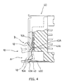
- the connector 40 comprises a housing body 42, a plurality of contact elements 41 supported by the housing body 42, and a shield plate 43 fitted over the housing body 42.
- the housing body 42 has a pair of indented sections 44 for not. only receiving the protruded sections 18 but also forming a raised section 4b therebetween where the contact sections 41A of the contact elements 41 are provided for contact with the contact sections 14A when the raised section 45 are put into the recess 19 of the connector 10.
- the shield plate 43 extend forwardly a little more than the front face of the raised section 45 and outwardly at the front land to form an inlet section 43A. It forms outer walls of the indented sections 44 to guide and support the protruded sections 18 of the connector 10.
- a pair of engaging slits 43B are provided in the upper face of the shield plate 43 for engagement. with the engaging claws 21A of the connector 10 for making lock.
- a pair of spring arms 43D are provided on opposite sides of the shield plate 43 for spring contact with the protective sections 16A, thus making shield connection therebetween, when the protruded sections 18 are fitted in the indented sections 44.
- a plurality of grooves 42A are provided in the front Lace of the raised section 45 for receiving the contact sections 41A of contact elements 41.
- the contact sections 41A have sufficient height and width to make contact with the contact sections 14A of the contact elements 14.
- the width and depth of the grooves 42A are made such that the front end of the connector 10 does not make any contact with the contact sections 41A upon plugging.
- connection sections 41B which are to be soldered to traces of circultry on a circuit board P.
- the shield plate 43 has a pair of downward legs 43C to be put through apertures of the circuit board P for making connection by soldering.
- the connector according to the invention comprises the guiding sections or protruded sections and the indented sections provided on opposite sides of the connector so that not only the height of the connector is minimized but also the tilting of the connector upon plugging is minimized.
- Part of the shield plate covers the guiding section to protect the connector against forced plugging.
Landscapes
- Details Of Connecting Devices For Male And Female Coupling (AREA)
- Coupling Device And Connection With Printed Circuit (AREA)
Applications Claiming Priority (2)
| Application Number | Priority Date | Filing Date | Title |
|---|---|---|---|
| JP2000031369 | 2000-02-09 | ||
| JP2000031369A JP2001223057A (ja) | 2000-02-09 | 2000-02-09 | 電気コネクタ |
Publications (2)
| Publication Number | Publication Date |
|---|---|
| EP1124290A2 true EP1124290A2 (fr) | 2001-08-16 |
| EP1124290A3 EP1124290A3 (fr) | 2002-07-24 |
Family
ID=18556133
Family Applications (1)
| Application Number | Title | Priority Date | Filing Date |
|---|---|---|---|
| EP01102515A Withdrawn EP1124290A3 (fr) | 2000-02-09 | 2001-02-05 | Connecteur électrique |
Country Status (3)
| Country | Link |
|---|---|
| US (1) | US6379187B2 (fr) |
| EP (1) | EP1124290A3 (fr) |
| JP (1) | JP2001223057A (fr) |
Cited By (3)
| Publication number | Priority date | Publication date | Assignee | Title |
|---|---|---|---|---|
| GB2378827A (en) * | 2001-08-17 | 2003-02-19 | Yazaki Corp | Connector with notch to obstruct incorrect counterpart |
| GB2411778A (en) * | 2004-03-02 | 2005-09-07 | Smk Kk | Reinforcing connector using part of shield |
| DE102006020955A1 (de) * | 2006-05-05 | 2007-11-15 | Lumberg Connect Gmbh | Andruckkontakt |
Families Citing this family (56)
| Publication number | Priority date | Publication date | Assignee | Title |
|---|---|---|---|---|
| FR2769165B1 (fr) | 1997-09-26 | 2002-11-29 | Technical Maintenance Corp | Systeme sans fil a transmission numerique pour haut-parleurs |
| FR2781591B1 (fr) | 1998-07-22 | 2000-09-22 | Technical Maintenance Corp | Systeme de reproduction audiovisuelle |
| FR2781580B1 (fr) | 1998-07-22 | 2000-09-22 | Technical Maintenance Corp | Circuit de commande de son pour systeme de reproduction audiovisuelle numerique intelligent |
| FR2805377B1 (fr) | 2000-02-23 | 2003-09-12 | Touchtunes Music Corp | Procede de commande anticipee d'une selection, systeme numerique et juke-box permettant la mise en oeuvre du procede |
| FR2805060B1 (fr) | 2000-02-16 | 2005-04-08 | Touchtunes Music Corp | Procede de reception de fichiers lors d'un telechargement |
| FR2808906B1 (fr) | 2000-05-10 | 2005-02-11 | Touchtunes Music Corp | Dispositif et procede de gestion a distance d'un reseau de systemes de reproduction d'informations audiovisuelles |
| FR2811114B1 (fr) | 2000-06-29 | 2002-12-27 | Touchtunes Music Corp | Dispositif et procede de communication entre un systeme de reproduction d'informations audiovisuelles et d'une machine electronique de divertissement |
| FR2814085B1 (fr) | 2000-09-15 | 2005-02-11 | Touchtunes Music Corp | Procede de divertissement base sur les jeux concours a choix multiples |
| JP2002373738A (ja) * | 2001-06-11 | 2002-12-26 | Molex Inc | 挿入ガイド付きのシールドコネクタ |
| US6568961B1 (en) * | 2002-04-29 | 2003-05-27 | Lear Corporation | Wireform contactor assembly |
| US10373420B2 (en) | 2002-09-16 | 2019-08-06 | Touchtunes Music Corporation | Digital downloading jukebox with enhanced communication features |
| US9646339B2 (en) | 2002-09-16 | 2017-05-09 | Touchtunes Music Corporation | Digital downloading jukebox system with central and local music servers |
| US7822687B2 (en) | 2002-09-16 | 2010-10-26 | Francois Brillon | Jukebox with customizable avatar |
| US12100258B2 (en) | 2002-09-16 | 2024-09-24 | Touchtunes Music Company, Llc | Digital downloading jukebox with enhanced communication features |
| US8584175B2 (en) | 2002-09-16 | 2013-11-12 | Touchtunes Music Corporation | Digital downloading jukebox system with user-tailored music management, communications, and other tools |
| US8332895B2 (en) | 2002-09-16 | 2012-12-11 | Touchtunes Music Corporation | Digital downloading jukebox system with user-tailored music management, communications, and other tools |
| US8103589B2 (en) | 2002-09-16 | 2012-01-24 | Touchtunes Music Corporation | Digital downloading jukebox system with central and local music servers |
| US11029823B2 (en) | 2002-09-16 | 2021-06-08 | Touchtunes Music Corporation | Jukebox with customizable avatar |
| JP3969400B2 (ja) | 2004-04-09 | 2007-09-05 | 松下電工株式会社 | コネクタ |
| JP2007103249A (ja) * | 2005-10-06 | 2007-04-19 | Japan Aviation Electronics Industry Ltd | 電気コネクタ |
| US9171419B2 (en) * | 2007-01-17 | 2015-10-27 | Touchtunes Music Corporation | Coin operated entertainment system |
| US12450978B2 (en) | 2007-01-17 | 2025-10-21 | Touchtunes Music Company Llc. | Coin operated entertainment system |
| JP4494441B2 (ja) * | 2007-07-03 | 2010-06-30 | 日本航空電子工業株式会社 | 電気コネクタ |
| US10290006B2 (en) | 2008-08-15 | 2019-05-14 | Touchtunes Music Corporation | Digital signage and gaming services to comply with federal and state alcohol and beverage laws and regulations |
| WO2010005569A1 (fr) | 2008-07-09 | 2010-01-14 | Touchtunes Music Corporation | Jukebox de téléchargement numérique à caractéristiques d'amélioration des recettes |
| JP4849109B2 (ja) * | 2008-09-10 | 2012-01-11 | パナソニック電工株式会社 | レセプタクルコネクタ及びその製造方法 |
| JP4558824B2 (ja) | 2008-09-19 | 2010-10-06 | 株式会社アイペックス | コネクタ装置 |
| CN106056367A (zh) | 2009-03-18 | 2016-10-26 | 踏途音乐公司 | 娱乐服务器及相关的社交网络系统 |
| US9292166B2 (en) | 2009-03-18 | 2016-03-22 | Touchtunes Music Corporation | Digital jukebox device with improved karaoke-related user interfaces, and associated methods |
| US9285831B2 (en) | 2009-09-17 | 2016-03-15 | Henge Docks Llc | Docking station for portable electronics |
| US8512079B2 (en) * | 2009-09-17 | 2013-08-20 | Henge Docks Llc | Docking station for an electronic device with improved electrical interface |
| CA2787380C (fr) | 2010-01-26 | 2017-05-09 | Francois Beaumier | Dispositif de juke-box numerique ayant des interfaces d'utilisateur perfectionnees, et procedes associes |
| CA2800738C (fr) | 2010-05-28 | 2016-01-26 | Apple Inc. | Connecteur a double orientation a contacts externes |
| TWM420090U (en) * | 2011-06-16 | 2012-01-01 | Molex Taiwan Ltd | Electrical connection device |
| CN110097416B (zh) | 2011-09-18 | 2022-05-10 | 踏途音乐公司 | 具有卡拉ok和照相亭功能的数字点播设备及相关方法 |
| US9293876B2 (en) | 2011-11-07 | 2016-03-22 | Apple Inc. | Techniques for configuring contacts of a connector |
| US8708745B2 (en) | 2011-11-07 | 2014-04-29 | Apple Inc. | Dual orientation electronic connector |
| US9112327B2 (en) | 2011-11-30 | 2015-08-18 | Apple Inc. | Audio/video connector for an electronic device |
| US11151224B2 (en) | 2012-01-09 | 2021-10-19 | Touchtunes Music Corporation | Systems and/or methods for monitoring audio inputs to jukebox devices |
| US9093803B2 (en) | 2012-09-07 | 2015-07-28 | Apple Inc. | Plug connector |
| US9160129B2 (en) | 2012-09-11 | 2015-10-13 | Apple Inc. | Connectors and methods for manufacturing connectors |
| WO2014040231A1 (fr) | 2012-09-11 | 2014-03-20 | Apple Inc. | Connecteurs et procédés pour fabriquer des connecteurs |
| US9059531B2 (en) | 2012-09-11 | 2015-06-16 | Apple Inc. | Connectors and methods for manufacturing connectors |
| US9325097B2 (en) | 2012-11-16 | 2016-04-26 | Apple Inc. | Connector contacts with thermally conductive polymer |
| US20140206209A1 (en) | 2013-01-24 | 2014-07-24 | Apple Inc. | Reversible usb connector |
| TWI500222B (zh) * | 2013-07-12 | 2015-09-11 | Ccp Contact Probes Co Ltd | 連接器組合 |
| US9650814B2 (en) | 2013-12-31 | 2017-05-16 | Henge Docks Llc | Alignment and drive system for motorized horizontal docking station |
| US9927838B2 (en) | 2013-12-31 | 2018-03-27 | Henge Docks Llc | Sensor system for docking station |
| CN203760751U (zh) * | 2014-02-25 | 2014-08-06 | 番禺得意精密电子工业有限公司 | 电连接器组件 |
| US9727084B2 (en) | 2015-10-23 | 2017-08-08 | Henge Docks Llc | Drivetrain for a motorized docking station |
| US9575510B1 (en) | 2015-10-23 | 2017-02-21 | Matthew Leigh Vroom | Precision docking station for an electronic device having integrated retention mechanism |
| US9811118B2 (en) | 2015-10-23 | 2017-11-07 | Henge Docks Llc | Secure assembly for a docking station |
| JP6634856B2 (ja) * | 2016-02-04 | 2020-01-22 | 第一精工株式会社 | コネクタ装置 |
| US9935668B1 (en) | 2017-02-16 | 2018-04-03 | Datron World Communications, Inc. | Detachment mechanism and indicator for mobile mount portable radio and method for the same |
| US10365688B1 (en) | 2018-04-19 | 2019-07-30 | Henge Docks Llc | Alignment sleeve for docking station |
| JP7646428B2 (ja) | 2021-04-13 | 2025-03-17 | TE Connectivity Japan合同会社 | 電気コネクタおよび電気コネクタ組立体 |
Family Cites Families (11)
| Publication number | Priority date | Publication date | Assignee | Title |
|---|---|---|---|---|
| US5267881A (en) * | 1992-09-24 | 1993-12-07 | Hirose Electric Co., Ltd. | Electrical connector |
| US5295843A (en) * | 1993-01-19 | 1994-03-22 | The Whitaker Corporation | Electrical connector for power and signal contacts |
| US5575674A (en) * | 1994-07-29 | 1996-11-19 | The Whitaker Corporation | Connector adapted for hermaphroditic construction |
| JP3746515B2 (ja) * | 1995-03-16 | 2006-02-15 | ザ ウィタカー コーポレーション | 携帯電話接続システム |
| US6007379A (en) * | 1997-02-10 | 1999-12-28 | Thomas & Betts International, Inc. | Electrical connector assembly |
| US6007359A (en) * | 1997-11-25 | 1999-12-28 | Itt Manufacturing Enterprises, Inc. | Receptacle connector |
| KR100413026B1 (ko) * | 1998-04-30 | 2004-03-22 | 삼성전자주식회사 | 커넥터어셈블리 |
| FR2781094B1 (fr) * | 1998-07-09 | 2000-08-18 | Alsthom Cge Alcatel | Ensemble de connexon mixte |
| TW422433U (en) * | 1998-10-30 | 2001-02-11 | Hon Hai Prec Ind Co Ltd | Electrical connector |
| JP2000223191A (ja) * | 1999-01-27 | 2000-08-11 | Mitsumi Electric Co Ltd | 小型コネクタ |
| TW427564U (en) * | 1999-12-14 | 2001-03-21 | Hon Hai Prec Ind Co Ltd | Stack-type electrical connector |
-
2000
- 2000-02-09 JP JP2000031369A patent/JP2001223057A/ja active Pending
-
2001
- 2001-01-08 US US09/755,079 patent/US6379187B2/en not_active Expired - Fee Related
- 2001-02-05 EP EP01102515A patent/EP1124290A3/fr not_active Withdrawn
Cited By (6)
| Publication number | Priority date | Publication date | Assignee | Title |
|---|---|---|---|---|
| GB2378827A (en) * | 2001-08-17 | 2003-02-19 | Yazaki Corp | Connector with notch to obstruct incorrect counterpart |
| US6837750B2 (en) | 2001-08-17 | 2005-01-04 | Yazaki Corporation | Connector and connector housing having a notch formed in an edge of the connector housing to facilitate connection |
| GB2378827B (en) * | 2001-08-17 | 2005-06-08 | Yazaki Corp | A connector with connector housing having a notch to obstruct incorrect fitting |
| GB2411778A (en) * | 2004-03-02 | 2005-09-07 | Smk Kk | Reinforcing connector using part of shield |
| DE102006020955A1 (de) * | 2006-05-05 | 2007-11-15 | Lumberg Connect Gmbh | Andruckkontakt |
| DE102006020955B4 (de) * | 2006-05-05 | 2010-12-02 | Lumberg Connect Gmbh | Andruckkontakt und Andruckverbinder |
Also Published As
| Publication number | Publication date |
|---|---|
| US20010012718A1 (en) | 2001-08-09 |
| EP1124290A3 (fr) | 2002-07-24 |
| JP2001223057A (ja) | 2001-08-17 |
| US6379187B2 (en) | 2002-04-30 |
Similar Documents
| Publication | Publication Date | Title |
|---|---|---|
| EP1124290A2 (fr) | Connecteur électrique | |
| US6358089B1 (en) | Connector for printed wiring board | |
| EP1519451B1 (fr) | Connecteur électrique avec des moyens de réglage | |
| EP0108608B1 (fr) | Assemblage d'un connecteur électrique | |
| US6241556B1 (en) | Retention member for connector | |
| US7052320B2 (en) | Electrical connector having shielding plates | |
| US4908335A (en) | One-piece molded insulating housing for a circular din connector | |
| US7004792B2 (en) | Electrical connector | |
| EP1635425B1 (fr) | Terminal de connexion | |
| US5674078A (en) | Multi-directional interface header assembly | |
| US7273397B2 (en) | Electrical connector having flexible mating portion | |
| EP1791217A2 (fr) | Connecteur femelle et connecteur mâle | |
| US6629859B2 (en) | Shielded connector assembly | |
| EP0407864B1 (fr) | Connecteur de bordure pour plaque de circuit imprimé | |
| US4995819A (en) | Set of strips of electrical terminals and a method of loading an electrical connector with said terminals | |
| KR101052177B1 (ko) | 전기 커넥터 | |
| US20040166739A1 (en) | Electrical connector with a terminal pin stabilizing plate | |
| EP1315252B1 (fr) | Connecteur électrique avec système amélioré de décharge électrostatique | |
| US7210965B1 (en) | Cable connector assembly | |
| US12438303B2 (en) | Plug connector with blocking bar | |
| EP1801933A1 (fr) | Connecteur | |
| JP3755652B2 (ja) | シールドコネクタ組立体 | |
| EP1315247A2 (fr) | Connecteur électrique ayant des moyens d'alignement et de recouvrement | |
| EP0797277A2 (fr) | Carte de PC et châssis pour cartes en kit | |
| KR100494276B1 (ko) | 카드 에지 커넥터 |
Legal Events
| Date | Code | Title | Description |
|---|---|---|---|
| PUAI | Public reference made under article 153(3) epc to a published international application that has entered the european phase |
Free format text: ORIGINAL CODE: 0009012 |
|
| AK | Designated contracting states |
Kind code of ref document: A2 Designated state(s): AT BE CH CY DE DK ES FI FR GB GR IE IT LI LU MC NL PT SE TR |
|
| AX | Request for extension of the european patent |
Free format text: AL;LT;LV;MK;RO;SI |
|
| PUAL | Search report despatched |
Free format text: ORIGINAL CODE: 0009013 |
|
| AK | Designated contracting states |
Kind code of ref document: A3 Designated state(s): AT BE CH CY DE DK ES FI FR GB GR IE IT LI LU MC NL PT SE TR |
|
| AX | Request for extension of the european patent |
Free format text: AL;LT;LV;MK;RO;SI |
|
| AKX | Designation fees paid | ||
| REG | Reference to a national code |
Ref country code: DE Ref legal event code: 8566 |
|
| STAA | Information on the status of an ep patent application or granted ep patent |
Free format text: STATUS: THE APPLICATION IS DEEMED TO BE WITHDRAWN |
|
| 18D | Application deemed to be withdrawn |
Effective date: 20030125 |