EP1124292A2 - Réseau répartiteur de signaux d'antenne pour habitations pour la transmission de programmes de télévision et/ou de radio - Google Patents
Réseau répartiteur de signaux d'antenne pour habitations pour la transmission de programmes de télévision et/ou de radio Download PDFInfo
- Publication number
- EP1124292A2 EP1124292A2 EP01103004A EP01103004A EP1124292A2 EP 1124292 A2 EP1124292 A2 EP 1124292A2 EP 01103004 A EP01103004 A EP 01103004A EP 01103004 A EP01103004 A EP 01103004A EP 1124292 A2 EP1124292 A2 EP 1124292A2
- Authority
- EP
- European Patent Office
- Prior art keywords
- distribution network
- center
- network according
- antenna
- address
- Prior art date
- Legal status (The legal status is an assumption and is not a legal conclusion. Google has not performed a legal analysis and makes no representation as to the accuracy of the status listed.)
- Granted
Links
Images


Classifications
-
- H—ELECTRICITY
- H01—ELECTRIC ELEMENTS
- H01R—ELECTRICALLY-CONDUCTIVE CONNECTIONS; STRUCTURAL ASSOCIATIONS OF A PLURALITY OF MUTUALLY-INSULATED ELECTRICAL CONNECTING ELEMENTS; COUPLING DEVICES; CURRENT COLLECTORS
- H01R24/00—Two-part coupling devices, or either of their cooperating parts, characterised by their overall structure
- H01R24/38—Two-part coupling devices, or either of their cooperating parts, characterised by their overall structure having concentrically or coaxially arranged contacts
- H01R24/40—Two-part coupling devices, or either of their cooperating parts, characterised by their overall structure having concentrically or coaxially arranged contacts specially adapted for high frequency
- H01R24/52—Two-part coupling devices, or either of their cooperating parts, characterised by their overall structure having concentrically or coaxially arranged contacts specially adapted for high frequency mounted in or to a panel or structure
- H01R24/525—Outlets
-
- H—ELECTRICITY
- H04—ELECTRIC COMMUNICATION TECHNIQUE
- H04H—BROADCAST COMMUNICATION
- H04H20/00—Arrangements for broadcast or for distribution combined with broadcast
- H04H20/53—Arrangements specially adapted for specific applications, e.g. for traffic information or for mobile receivers
- H04H20/61—Arrangements specially adapted for specific applications, e.g. for traffic information or for mobile receivers for local area broadcast, e.g. instore broadcast
- H04H20/63—Arrangements specially adapted for specific applications, e.g. for traffic information or for mobile receivers for local area broadcast, e.g. instore broadcast to plural spots in a confined site, e.g. MATV [Master Antenna Television]
-
- H—ELECTRICITY
- H04—ELECTRIC COMMUNICATION TECHNIQUE
- H04N—PICTORIAL COMMUNICATION, e.g. TELEVISION
- H04N7/00—Television systems
- H04N7/10—Adaptations for transmission by electrical cable
- H04N7/106—Adaptations for transmission by electrical cable for domestic distribution
-
- H—ELECTRICITY
- H01—ELECTRIC ELEMENTS
- H01R—ELECTRICALLY-CONDUCTIVE CONNECTIONS; STRUCTURAL ASSOCIATIONS OF A PLURALITY OF MUTUALLY-INSULATED ELECTRICAL CONNECTING ELEMENTS; COUPLING DEVICES; CURRENT COLLECTORS
- H01R2103/00—Two poles
Definitions
- the invention relates to an antenna signal distribution network, in particular a home distribution network for the transmission of TV and / or radio programs according to the generic term of claim 1 or an associated junction box Claim 17.
- Distribution boards for the reception of television or radio programs are well known. For example through a satellite antenna TV or radio programs received and in fed a house distribution network.
- the antenna signal will via one or more coaxial distribution cables to antenna sockets headed from which it is connected Can tap participants. According to the needs are in the network Processing plants, switching matrices, distributors, taps or amplifier arranged. In addition you can terrestrial programs via additional antennas received and fed into the distribution network.
- EP 0 865 119 A2 describes a correspondingly more comprehensive one Distribution network known, which also one or more lines originating from a control center in which one or more junction boxes connected in series are provided. Then at the junction boxes one or more connection elements accessible from the outside be trained to enable a participant here one or more of the services provided to receive or use. This can be done equally also apply to corresponding return lines.
- the object of the present invention is therefore starting from the generic state of the art improved antenna signal home distribution network with improved To create junction boxes, its construction, expansion, Maintenance and operation is easier than before.
- a significant improvement over conventional solutions is thereby in the distribution network according to the invention achieved that the junction boxes in the distribution network electrical and / or mechanical address blocks so are equipped that all junction boxes in the distribution network clearly from a control unit or control center are identifiable.
- junction boxes already with an address module from the manufacturer be equipped with a unique identification code sends, the identification code no longer changeable and / or adjustable, but is legible.
- junction boxes are additionally equipped with a from the control center through the address module controllable switching element that the RF signal flow can interrupt, especially if that Switching element at the same time the coaxial cable harness suitable for shaft resistance completes.
- antenna signal distribution systems with such antenna sockets can easily be a coaxial distribution line be extended or shortened by the Head office out in the original last one and in the new one last can of the strand the switching element is actuated.
- Such a technical feature also does not allow it required user interfaces and wiring harnesses from decoupling from the control center and thus the shield tightness to increase a distribution system.
- Antenna sockets when billing should be done It can be determined exactly at the headquarters when and what programs or multimedia services about a junction box has been received by a subscriber are. Are address blocks and switching elements of the subscriber outputs assigned unpunctual payers of the Central from and thus without entering the residential units Can be disconnected from the network with little effort.
- the distribution system according to the invention ultimately enables especially with the addition of a microprocessor in the central processing unit that from this control unit or headquarters from communicating with everyone and in particular with the junction boxes connected in series as well as between junction boxes.
- an intelligent central control unit able to recognize whether in modular systems in a wiring harness an impermissible function module configuration has been inserted.
- an inventive Home distribution network can be from the central office or control unit off after an analysis of the already connected Sockets and / or functional modules as well as the connecting cable lengths be informed to the user whether the insertion of a additional module or a new junction box is possible or whether the signal level for such Case not enough.
- Such a network also allows easily distribute access rights differently, too change and / or to assign or program packages only to to deliver certain doses.
- a system according to the invention also permits series connection several receivers, as opposed to conventional ones Networks the origin of the receiver switching signals can be localized is and exactly there the desired data can be sent.
- the antenna signal home distribution system quick inventory and compatibility check of all Network components allow simple archiving or Documentation of the system structure allowed as well as a convenient Extension or change of the distribution lines allows.
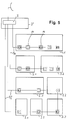
- Figure 1 is an antenna signal distribution system for Reception of television and / or radio programs shown.
- the programs are received by an antenna 5 and in a central control unit 7 where it is directed to a or several coaxial cable runs 9 are distributed.
- lines 9a to 9d are laid, to different floors 1 to 4 and / or rooms 1.1 to 4.1.
- Address blocks 21 equipped so that they are from the headquarters 7 'with the central control unit 7 by means of a communication unit placed there clearly can be identified and addressed. The address the can can already be changed by the manufacturer set or by the installer after installing the Plant can be awarded. As address block 21 are both mechanical as well as electronic components.
- Distribution system sections that are not required are in the system described can be switched off in an elegant way, which makes the Interference emission of the network can be reduced.
- control center 7 address blocks 21 and switching elements 23 necessary data exchange takes place via the coaxial connection cable 9 in one for the transmission of television and radio programs unused frequency range instead.
- FIG. 2 shows schematically the structure of a junction box 11, 11 '.
- the antenna signal is via an incoming Coaxial cable 19 ', i.e. via the inner conductor 19a 'in the Antenna socket 11, 11 'directed and there for example via a circuit board to one or more Subscriber interfaces 18 and to a further one Coaxial cable 19 "distributed.
- the address block 21 and the switching element 23 - for example bistable that can be operated via a DC voltage High frequency relay - arranged so that over the coaxial cable 19 'communication between headquarters and the Components 21 and 23 is possible.
- a switching command sent from the control center 7 can the conductor section 24 'separated in the switching element 23 and the conductor section 24 "in a branch line 19c can be closed, creating the connection to the leading Cable 19 "interrupted and between the inner conductor 19a 'and outer conductor 19b' of the leading wiring harness 19 'a terminating resistor 25 via an intermediate line 26, e.g. switched in the form of a housing cable which corresponds to the characteristic impedance of the coaxial line.
- This switching process is reversible so that a End box is convertible back into a through box.
- an address module 21 and a switching element 23 are provided in the antenna socket 11, 11 'shown in Figure 2 .
- Address blocks 21 and switching elements 23 are placed, in order to target user interfaces from the head office or To be able to switch function groups on or off.
- FIG 3 is a house distribution system with a modular structure Junction boxes 11, 11 'shown where the user has the option of customizing function blocks 14 to set or exchange accordingly. of course is also each function module with a unique address and equipped with a switching element and thus by can be switched on and off from the control center.
- the control center 7 is able to execute the switching commands To locate Receiver 29 and get exactly the ones you want Send program data.
- An intelligent control center can recognize whether an inadmissible Function module configuration was inserted or whether an extension with new function blocks 14 to errors leads.
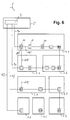
- FIG. 4 there is a house distribution system reproduced at the parallel to the coaxial Cable harnesses 9a to 9d for program transmission still additional data cables 10a to 10d are laid. At a Such system, it is possible to 10a to this data cable 10d for the communication between control center 7, address blocks 21 and switching elements 23 necessary data transmissions to use.
Landscapes
- Engineering & Computer Science (AREA)
- Signal Processing (AREA)
- Multimedia (AREA)
- Variable-Direction Aerials And Aerial Arrays (AREA)
- Small-Scale Networks (AREA)
- Details Of Television Systems (AREA)
- Two-Way Televisions, Distribution Of Moving Picture Or The Like (AREA)
Applications Claiming Priority (2)
| Application Number | Priority Date | Filing Date | Title |
|---|---|---|---|
| DE10005763 | 2000-02-10 | ||
| DE10005763A DE10005763B4 (de) | 2000-02-10 | 2000-02-10 | Antennensignal-Hausverteilnetz für die Übertragung von Fernseh- und/oder Rundfunkprogrammen |
Publications (3)
| Publication Number | Publication Date |
|---|---|
| EP1124292A2 true EP1124292A2 (fr) | 2001-08-16 |
| EP1124292A3 EP1124292A3 (fr) | 2003-08-06 |
| EP1124292B1 EP1124292B1 (fr) | 2006-06-21 |
Family
ID=7630372
Family Applications (1)
| Application Number | Title | Priority Date | Filing Date |
|---|---|---|---|
| EP01103004A Expired - Lifetime EP1124292B1 (fr) | 2000-02-10 | 2001-02-08 | Réseau répartiteur de signaux d'antenne pour habitations pour la transmission de programmes de télévision et/ou de radio |
Country Status (3)
| Country | Link |
|---|---|
| EP (1) | EP1124292B1 (fr) |
| AT (1) | ATE331322T1 (fr) |
| DE (2) | DE10005763B4 (fr) |
Cited By (1)
| Publication number | Priority date | Publication date | Assignee | Title |
|---|---|---|---|---|
| EP2717198A1 (fr) | 2012-10-04 | 2014-04-09 | Kathrein Werke KG | Prise multimédia ou prise pour antenne |
Families Citing this family (3)
| Publication number | Priority date | Publication date | Assignee | Title |
|---|---|---|---|---|
| DE102005036810B4 (de) | 2005-08-04 | 2007-09-06 | Kathrein-Werke Kg | HF-Dose |
| DE102008029417A1 (de) * | 2008-06-23 | 2009-12-24 | Jultec Technology Gmbh | Konfigurierbare Antennensteckdose für den Einsatz in Satellitenempfangsanlagen mit teilnehmergesteuerten Frequenzumsetzern |
| DE102009026358A1 (de) | 2009-08-10 | 2011-02-17 | Rotek Microelectronic Gmbh & Co. Kg | Wandler für Steuerungsdaten und Verfahren zur Steuerung in einem Antennensignalverteilnetz |
Family Cites Families (7)
| Publication number | Priority date | Publication date | Assignee | Title |
|---|---|---|---|---|
| US4461032A (en) * | 1982-06-21 | 1984-07-17 | Zenith Radio Corporation | CATV Service controller |
| DE3727864C1 (en) * | 1987-08-20 | 1988-12-29 | Robert Neuberger | Enabling socket for providing authorised receivers with selected television programmes |
| DE3727865C1 (en) * | 1987-08-20 | 1988-12-29 | Robert Neuberger | Enabling socket for providing authorised receivers with selected television programmes |
| DE3840254C1 (fr) * | 1988-11-29 | 1990-06-07 | Neuberger Nachrichten- Und Antennentechnik Gmbh, 8000 Muenchen, De | |
| AU4377897A (en) * | 1996-07-26 | 1998-02-20 | Klein, Patrick | Decentralized subscriber access system |
| DE19633076A1 (de) * | 1996-08-16 | 1998-02-19 | Pansat Gmbh Communications Ele | Teilnehmeranschaltsystem |
| DE19709972A1 (de) * | 1997-03-11 | 1998-09-17 | Siemens Ag | Verteilnetz mit mindestens zwei auf getrennten Leitungen geführten Informationskanälen |
-
2000
- 2000-02-10 DE DE10005763A patent/DE10005763B4/de not_active Expired - Fee Related
-
2001
- 2001-02-08 AT AT01103004T patent/ATE331322T1/de active
- 2001-02-08 DE DE50110194T patent/DE50110194D1/de not_active Expired - Lifetime
- 2001-02-08 EP EP01103004A patent/EP1124292B1/fr not_active Expired - Lifetime
Cited By (2)
| Publication number | Priority date | Publication date | Assignee | Title |
|---|---|---|---|---|
| EP2717198A1 (fr) | 2012-10-04 | 2014-04-09 | Kathrein Werke KG | Prise multimédia ou prise pour antenne |
| DE102012019452A1 (de) | 2012-10-04 | 2014-04-10 | Kathrein-Werke Kg | Multimedia-Dose |
Also Published As
| Publication number | Publication date |
|---|---|
| DE10005763A1 (de) | 2001-08-30 |
| DE50110194D1 (de) | 2006-08-03 |
| ATE331322T1 (de) | 2006-07-15 |
| EP1124292A3 (fr) | 2003-08-06 |
| DE10005763B4 (de) | 2005-12-22 |
| EP1124292B1 (fr) | 2006-06-21 |
Similar Documents
| Publication | Publication Date | Title |
|---|---|---|
| DE69328754T2 (de) | Kabelverteilungssystem für Fernsehsignale und Anordnung von Elementen um ein solches System zu bauen | |
| EP0344609A2 (fr) | Système de transmission numérique pour installations domestiques | |
| DE60000653T2 (de) | Garnbehandlungssystem und verfahren zum betreiben eines garnbehandlungssystems | |
| EP0346614B1 (fr) | Procédé pour l'initialisation d'un système de transmission de données numériques | |
| EP0790541A2 (fr) | Dispositif de connexion pour un système d'installation électrique | |
| DE10155481A1 (de) | Einrichtung zur Steuerung und Überwachung der Freigabe von Empfangssignalen an Anschlussstellen innerhalb von kabelgebundenen Hausverteilungsanlagen | |
| EP0795994A2 (fr) | Méthode pour la mise à disposition d'un système de câbles dans la région domestique | |
| EP0437696B1 (fr) | Dispositif de connexion commuable à distance | |
| EP1124292B1 (fr) | Réseau répartiteur de signaux d'antenne pour habitations pour la transmission de programmes de télévision et/ou de radio | |
| EP0208959A1 (fr) | Système de communication | |
| EP0225461B1 (fr) | Réseau répartiteur de signaux pour habitations | |
| EP1760917B1 (fr) | Procédé et dispositif pour la configuration des n utilisateurs indépendents d'une installation de réception de satellite | |
| EP0791871A2 (fr) | Dispositif pour poursuivre ou interrompre la fourniture d'énergie électrique aux utilisateurs d'électricité | |
| DE69924285T2 (de) | Verfahren zur verteilung und übermittlung von kommunikations- und multimediasignalen sowie signalverteilungseinrichtung zur übermittlung der kommunikations- und multimediasignale | |
| EP0914742B1 (fr) | Systeme decentralise de raccordement d'abonnes | |
| EP1099991B1 (fr) | Procédé de configuration d'organes de commande pour ascenceurs | |
| DE10064370C1 (de) | Multischalter-Kopfgerät, Satellitenempfangsanlage sowie Verfahren zur Installation einer Satellitenempfansanlage | |
| EP1076376A2 (fr) | Appareil d' extension en forme d' embase d' antenne pour un appareil de réception, en particulier un appareil de réception des signaux vidéo numériques télédiffusés transmis à partir de stations terrestres (DVB-T) | |
| WO2002041582A1 (fr) | Dispositif de couplage permettant de coupler des reseaux locaux a un reseau global | |
| AT405998B (de) | Eib-gerät zum einbau in eine installationsdose | |
| EP1005228B1 (fr) | Circuit pour la transmission des signaux reçus sous forme analogique et/ou numérique | |
| DE202018106823U1 (de) | Busfähiges aneinanderreihbares Funktionsmodul | |
| DE202007017590U1 (de) | Umschalter mit teilnehmergesteuerten Umsetzern für Satellitenempfangsanlagen mit automatischer Betriebsmodusumschaltung | |
| DE19637070B4 (de) | Zusatzschaltung für Multimediakommunikation | |
| EP0371401A1 (fr) | Distributeur en étoile adressable à distance pour signaux de télévision |
Legal Events
| Date | Code | Title | Description |
|---|---|---|---|
| PUAI | Public reference made under article 153(3) epc to a published international application that has entered the european phase |
Free format text: ORIGINAL CODE: 0009012 |
|
| AK | Designated contracting states |
Kind code of ref document: A2 Designated state(s): AT BE CH CY DE DK ES FI FR GB GR IE IT LI LU MC NL PT SE TR |
|
| AX | Request for extension of the european patent |
Free format text: AL;LT;LV;MK;RO;SI |
|
| PUAL | Search report despatched |
Free format text: ORIGINAL CODE: 0009013 |
|
| AK | Designated contracting states |
Designated state(s): AT BE CH CY DE DK ES FI FR GB GR IE IT LI LU MC NL PT SE TR |
|
| AX | Request for extension of the european patent |
Extension state: AL LT LV MK RO SI |
|
| RIC1 | Information provided on ipc code assigned before grant |
Ipc: 7H 04H 1/04 B Ipc: 7H 01R 13/646 A Ipc: 7H 04N 7/10 B Ipc: 7H 04H 1/02 B |
|
| 17P | Request for examination filed |
Effective date: 20031007 |
|
| AKX | Designation fees paid |
Designated state(s): AT BE DE NL |
|
| 17Q | First examination report despatched |
Effective date: 20040330 |
|
| GRAP | Despatch of communication of intention to grant a patent |
Free format text: ORIGINAL CODE: EPIDOSNIGR1 |
|
| GRAS | Grant fee paid |
Free format text: ORIGINAL CODE: EPIDOSNIGR3 |
|
| GRAA | (expected) grant |
Free format text: ORIGINAL CODE: 0009210 |
|
| AK | Designated contracting states |
Kind code of ref document: B1 Designated state(s): AT BE DE NL |
|
| REF | Corresponds to: |
Ref document number: 50110194 Country of ref document: DE Date of ref document: 20060803 Kind code of ref document: P |
|
| PLBE | No opposition filed within time limit |
Free format text: ORIGINAL CODE: 0009261 |
|
| STAA | Information on the status of an ep patent application or granted ep patent |
Free format text: STATUS: NO OPPOSITION FILED WITHIN TIME LIMIT |
|
| 26N | No opposition filed |
Effective date: 20070322 |
|
| PGFP | Annual fee paid to national office [announced via postgrant information from national office to epo] |
Ref country code: NL Payment date: 20140220 Year of fee payment: 14 |
|
| PGFP | Annual fee paid to national office [announced via postgrant information from national office to epo] |
Ref country code: BE Payment date: 20140219 Year of fee payment: 14 |
|
| PG25 | Lapsed in a contracting state [announced via postgrant information from national office to epo] |
Ref country code: BE Free format text: LAPSE BECAUSE OF NON-PAYMENT OF DUE FEES Effective date: 20150228 |
|
| REG | Reference to a national code |
Ref country code: NL Ref legal event code: V1 Effective date: 20150901 |
|
| PG25 | Lapsed in a contracting state [announced via postgrant information from national office to epo] |
Ref country code: NL Free format text: LAPSE BECAUSE OF NON-PAYMENT OF DUE FEES Effective date: 20150901 |
|
| PGFP | Annual fee paid to national office [announced via postgrant information from national office to epo] |
Ref country code: AT Payment date: 20160218 Year of fee payment: 16 |
|
| PGFP | Annual fee paid to national office [announced via postgrant information from national office to epo] |
Ref country code: DE Payment date: 20170222 Year of fee payment: 17 |
|
| REG | Reference to a national code |
Ref country code: AT Ref legal event code: MM01 Ref document number: 331322 Country of ref document: AT Kind code of ref document: T Effective date: 20170208 |
|
| PG25 | Lapsed in a contracting state [announced via postgrant information from national office to epo] |
Ref country code: AT Free format text: LAPSE BECAUSE OF NON-PAYMENT OF DUE FEES Effective date: 20170208 |
|
| REG | Reference to a national code |
Ref country code: DE Ref legal event code: R082 Ref document number: 50110194 Country of ref document: DE Representative=s name: FLACH BAUER STAHL PATENTANWAELTE PARTNERSCHAFT, DE |
|
| REG | Reference to a national code |
Ref country code: DE Ref legal event code: R119 Ref document number: 50110194 Country of ref document: DE |
|
| PG25 | Lapsed in a contracting state [announced via postgrant information from national office to epo] |
Ref country code: DE Free format text: LAPSE BECAUSE OF NON-PAYMENT OF DUE FEES Effective date: 20180901 |