EP1124298A1 - Boítier pour appareillage installé sous plancher - Google Patents
Boítier pour appareillage installé sous plancher Download PDFInfo
- Publication number
- EP1124298A1 EP1124298A1 EP01100047A EP01100047A EP1124298A1 EP 1124298 A1 EP1124298 A1 EP 1124298A1 EP 01100047 A EP01100047 A EP 01100047A EP 01100047 A EP01100047 A EP 01100047A EP 1124298 A1 EP1124298 A1 EP 1124298A1
- Authority
- EP
- European Patent Office
- Prior art keywords
- frame
- device box
- slot
- box according
- underfloor device
- Prior art date
- Legal status (The legal status is an assumption and is not a legal conclusion. Google has not performed a legal analysis and makes no representation as to the accuracy of the status listed.)
- Granted
Links
- 210000002105 tongue Anatomy 0.000 claims abstract description 19
- 238000009434 installation Methods 0.000 claims abstract description 10
- 230000001681 protective effect Effects 0.000 claims description 5
- 238000010276 construction Methods 0.000 description 3
- 238000003780 insertion Methods 0.000 description 1
- 230000037431 insertion Effects 0.000 description 1
Images

Classifications
-
- H—ELECTRICITY
- H02—GENERATION; CONVERSION OR DISTRIBUTION OF ELECTRIC POWER
- H02G—INSTALLATION OF ELECTRIC CABLES OR LINES, OR OF COMBINED OPTICAL AND ELECTRIC CABLES OR LINES
- H02G3/00—Installations of electric cables or lines or protective tubing therefor in or on buildings, equivalent structures or vehicles
- H02G3/02—Details
- H02G3/08—Distribution boxes; Connection or junction boxes
- H02G3/18—Distribution boxes; Connection or junction boxes providing line outlets
- H02G3/185—Floor outlets and access cups
Definitions
- the invention relates to an underfloor device socket with a Carpet protective frame and with a frame-shaped connected to it Housing wall, with two opposite Flat slides are guided on the sides of the housing wall, which are spring-loaded and after releasing a lock for locking below the floor with the bottom edge of the edge the opening for the underfloor box can be engaged are and with the slider with one in their longitudinal direction extending slot are provided in the guide cams intervene that protrude from the wall.
- the invention has for its object an improved To propose underfloor box of this type, the easier in construction and handling.
- the invention with a Underfloor device box of the type mentioned initially proposed that the lock is made at right angles to the direction of movement of the Slider movable stop tongues, which at one in the level of the slider, but upwards from this projecting stop tab.
- This configuration has the advantage that the locking after inserting the underfloor device box very much is easily accessible from the top without having to make large cutouts necessary for a grip to unlock the slide would be.
- the stop tongues can on the inside edge of the frame and in front of an open one Slot be arranged in which the stop tab is movable is led.
- the stop tongues can be hook-shaped in a simple manner be formed and in the area of the slot protrude with a protruding protrusion so that to unlock only a relatively small outward pivoting movement of the stop tongues becomes necessary, for example with one from above into the slot for guiding the stop tab inserted tool is possible.
- the slider also with the new underfloor box Help expand their guide slot for the purpose of their Mounted over the larger heads of the guide cams and then be pushed into their locked position, or when removing an underfloor box from its mounting position back into the locked position must be performed, it is in further development of the invention advantageous if the projection is intended for the locking Stop tongue on the side facing the corner of the frame in the area of the stop tab of the slide with a beveled End edge is provided.
- At least two guide cams can be provided in this embodiment, the their enlarged heads in corresponding widenings of the slot are insertable to enable assembly.
- These two guide cams guarantee a straight Sliding movement of the slide and thereby also secure an exact hold in the installation position. That kind of leadership is only made possible by the other type of locking, where a swiveling movement around the guide cam - as in the known design - for the purpose of releasing a lock is not necessary.
- the two extensions of the Slot which is only for mounting the slide on the frame are needed are appropriately arranged so that they neither in the retracted initial position of the slide still in the extended installation position with the position of the Guide cams match and so always a flawless Ensure leadership without the danger that the slider falls off its guide cams.
- one of the extensions at one end of the Slot may be provided by the one with the edge of the opening in the floor engaging end facing away.
- the new design enables production in a simple manner the carpet protection frame and the associated frame-shaped Wall made of plastic in a simple way as a one-piece part.
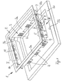
- Fig. 1 shows an underfloor box 1, the one rotating Carpet protective frame 2 and one of these inside staggered, frame-like surrounding housing wall 3, whose opposite wall parts 3a with stair-shaped trained rows of slots 4 are provided in the tabs protruding outwards from device cups, not shown are hooked in a known manner with installation devices are equipped.
- the other two, also each other opposite housing walls 3b are with the outside protruding guide cams 5 provided by slots 6 in Slides 7 are passed and with their extended Head these sliders 7 in parallel against the walls 3b hold.
- Each of the sliders 7 is at its from the frame corner opposite end provided with a tab 8, the side is bent and connected to the end of a tension spring 9 is the other end attached to a tab 10, the protrudes downwards from the carpet protective frame 2.
- tension springs 9 practice in the position shown in FIG. 1 Force on the slide 7, which move them outwards tries.
- the slider 7 are shown in the Position - see also Fig. 2 - but by locking tabs 11 held in the upper end of the walls 3b attached are and engage with projections 12 in a slot 13, which is in paragraph 14 between carpet protection frame 2 and wall 3b extends.
- a stop tab 15 guided over the upper edge 7a of the slide 7th protrudes upwards.
- the projection 12 therefore secures in the shown position of the stop tongues 11 in Fig. 1, 2 and 3 shown position of the slide 7th
- a projection 16 projects into the slot 13 second stop tongue 17 in, which serves the slide 7, which are each pulled outwards by the force of the springs 9 be prevented from reaching the end position in the extension 18 provided at the end of the slot 6 and another extension 19 to cover with the heads the guide cam 5 come. This position is only for the Assembly of the slide 7 required.
- the installation of the new underfloor box 1 is done as follows:
- the device box 1 is shown in FIG. 3 in the opening 22nd inserted until the carpet protective frame 1 on the - not shown - carpet is lying. It is then from up into the slot area 13a, for example with a Screwdriver engaged to the locking tabs 11 in Swing the sense of arrow A towards the inside of the frame and so the projection 12 from the path of movement of the slide 7 and bring his locking tab 15.
- the slider 7 will then by the action of the spring 9 in its position according to Fig. 4 brought.
- the projection 16 of the locking tongue 17 is not reached by the locking tab 15.
- the end position is created by the inclined edge 7b on the lower edge 20 of the floor 21 determined.
- the locking tongues 17 serve to prevent the built-in slider 7 unwanted so far by spring force that extensions 18 and 19 are moved to cover come with the heads of the guide cams 5. The slider 7 could then be removed from their leadership.
- the stop tongues 17 are an end stop for that mounted slide 7.
Landscapes
- Engineering & Computer Science (AREA)
- Architecture (AREA)
- Civil Engineering (AREA)
- Structural Engineering (AREA)
- Floor Finish (AREA)
- Supports Or Holders For Household Use (AREA)
- Food-Manufacturing Devices (AREA)
- Specific Sealing Or Ventilating Devices For Doors And Windows (AREA)
Applications Claiming Priority (2)
| Application Number | Priority Date | Filing Date | Title |
|---|---|---|---|
| DE20002200U | 2000-02-08 | ||
| DE20002200U DE20002200U1 (de) | 2000-02-08 | 2000-02-08 | Unterflurgerätedose |
Publications (2)
| Publication Number | Publication Date |
|---|---|
| EP1124298A1 true EP1124298A1 (fr) | 2001-08-16 |
| EP1124298B1 EP1124298B1 (fr) | 2007-08-22 |
Family
ID=7936997
Family Applications (1)
| Application Number | Title | Priority Date | Filing Date |
|---|---|---|---|
| EP01100047A Expired - Lifetime EP1124298B1 (fr) | 2000-02-08 | 2001-01-09 | Boîtier pour appareillage installé sous plancher |
Country Status (3)
| Country | Link |
|---|---|
| EP (1) | EP1124298B1 (fr) |
| AT (1) | ATE371287T1 (fr) |
| DE (2) | DE20002200U1 (fr) |
Cited By (2)
| Publication number | Priority date | Publication date | Assignee | Title |
|---|---|---|---|---|
| EP1811624A2 (fr) | 2006-01-23 | 2007-07-25 | OBO Bettermann GmbH & Co. KG. | Cassette d'installation au sol pour appareils d'installation |
| GB2450558A (en) * | 2007-06-29 | 2008-12-31 | Novar Ed & S Ltd | Service outlet floor box with depth adjustment |
Families Citing this family (2)
| Publication number | Priority date | Publication date | Assignee | Title |
|---|---|---|---|---|
| DE10303424B4 (de) * | 2003-01-29 | 2005-08-11 | Siemens Ag | Gehäuse eines Installationsgerätes |
| DE102004059815B4 (de) * | 2004-12-07 | 2011-03-24 | Obo Bettermann Gmbh & Co. Kg | Montageträger für Unterflurdose |
Citations (1)
| Publication number | Priority date | Publication date | Assignee | Title |
|---|---|---|---|---|
| EP0656676A1 (fr) * | 1993-12-02 | 1995-06-07 | Ackermann Limited | Boîtiers de sol |
-
2000
- 2000-02-08 DE DE20002200U patent/DE20002200U1/de not_active Expired - Lifetime
-
2001
- 2001-01-09 AT AT01100047T patent/ATE371287T1/de not_active IP Right Cessation
- 2001-01-09 EP EP01100047A patent/EP1124298B1/fr not_active Expired - Lifetime
- 2001-01-09 DE DE50112889T patent/DE50112889D1/de not_active Expired - Lifetime
Patent Citations (1)
| Publication number | Priority date | Publication date | Assignee | Title |
|---|---|---|---|---|
| EP0656676A1 (fr) * | 1993-12-02 | 1995-06-07 | Ackermann Limited | Boîtiers de sol |
Cited By (4)
| Publication number | Priority date | Publication date | Assignee | Title |
|---|---|---|---|---|
| EP1811624A2 (fr) | 2006-01-23 | 2007-07-25 | OBO Bettermann GmbH & Co. KG. | Cassette d'installation au sol pour appareils d'installation |
| EP1811624A3 (fr) * | 2006-01-23 | 2008-07-09 | OBO Bettermann GmbH & Co. KG. | Cassette d'installation au sol pour appareils d'installation |
| GB2450558A (en) * | 2007-06-29 | 2008-12-31 | Novar Ed & S Ltd | Service outlet floor box with depth adjustment |
| GB2450558B (en) * | 2007-06-29 | 2011-12-28 | Novar Ed & S Ltd | Service outlet floor box with depth adjustment |
Also Published As
| Publication number | Publication date |
|---|---|
| DE50112889D1 (de) | 2007-10-04 |
| DE20002200U1 (de) | 2000-04-20 |
| ATE371287T1 (de) | 2007-09-15 |
| EP1124298B1 (fr) | 2007-08-22 |
Similar Documents
| Publication | Publication Date | Title |
|---|---|---|
| DE2219714C2 (de) | Bandkassette | |
| DE69311012T2 (de) | Elektrischer Verbinder | |
| DE69120140T2 (de) | Feststellbarer Reissverschlussschieber | |
| DE4431879C2 (de) | Steckverbinder mit einem Verschlußteil | |
| DE2734788A1 (de) | Behaelter zum speichern von magnetbandkassetten | |
| DE102009032147B3 (de) | Sicherungseinrichtung | |
| DE2921343C2 (de) | Reißverschlußschieber mit Sperrschloß | |
| DE4420546A1 (de) | Gehäuseelement für elektrische Verbinder | |
| DE3800123C2 (de) | Montagevorrichtung zur Montage einer Magnetplatten-Kassette | |
| EP0384164A2 (fr) | Dispositif de verrouillage pour orifice de chargement d'unité d'entraînement de disques | |
| EP1124298A1 (fr) | Boítier pour appareillage installé sous plancher | |
| DE19541805A1 (de) | Elektrischer Verbinder | |
| DE2355656C2 (de) | Elektrische Steckverbindungsvorrichtung | |
| DE2701698C3 (de) | Abdeckvorrichtung zum Schutz von Führungsbahnen an Werkzeugmaschinen | |
| EP0627130B1 (fr) | Connecteur enfichable | |
| DE2719841C3 (de) | Mehrpolige Steckvorrichtung für Schwachstromanlagen, insbesondere Telefonanlagen | |
| DE3437585C2 (fr) | ||
| DE3015138A1 (de) | Verriegelbarer steckverbinder | |
| DE3510390C2 (de) | Abgangsstelle für Stromschienen mit Sicherheitsvorrichtung an Schienen-Verteilersystemen | |
| DE68911528T2 (de) | Kombinationsschloss. | |
| DE3636088C1 (en) | Device for insertion of an assembly into plug connectors and withdrawal of said assembly from plug connectors | |
| DE3403609C2 (fr) | ||
| CH646806A5 (en) | Lock with a locking function to be actuated after coin insertion | |
| AT500918A1 (de) | Steckdose mit sicherheitsverschluss und multifunktionsrahmen | |
| DE3922882A1 (de) | Verriegelbarer steckverbinder |
Legal Events
| Date | Code | Title | Description |
|---|---|---|---|
| PUAI | Public reference made under article 153(3) epc to a published international application that has entered the european phase |
Free format text: ORIGINAL CODE: 0009012 |
|
| AK | Designated contracting states |
Kind code of ref document: A1 Designated state(s): AT BE CH CY DE DK ES FI FR GB GR IE IT LI LU MC NL PT SE TR |
|
| AX | Request for extension of the european patent |
Free format text: AL;LT;LV;MK;RO;SI |
|
| 17P | Request for examination filed |
Effective date: 20020109 |
|
| AKX | Designation fees paid |
Free format text: AT BE CH CY DE DK ES FI FR GB GR IE IT LI LU MC NL PT SE TR |
|
| RAP1 | Party data changed (applicant data changed or rights of an application transferred) |
Owner name: OBO BETTERMANN GMBH & CO. KG |
|
| GRAP | Despatch of communication of intention to grant a patent |
Free format text: ORIGINAL CODE: EPIDOSNIGR1 |
|
| GRAS | Grant fee paid |
Free format text: ORIGINAL CODE: EPIDOSNIGR3 |
|
| GRAA | (expected) grant |
Free format text: ORIGINAL CODE: 0009210 |
|
| AK | Designated contracting states |
Kind code of ref document: B1 Designated state(s): AT BE CH CY DE DK ES FI FR GB GR IE IT LI LU MC NL PT SE TR |
|
| REG | Reference to a national code |
Ref country code: GB Ref legal event code: FG4D Free format text: NOT ENGLISH |
|
| REG | Reference to a national code |
Ref country code: CH Ref legal event code: EP |
|
| REG | Reference to a national code |
Ref country code: IE Ref legal event code: FG4D Free format text: LANGUAGE OF EP DOCUMENT: GERMAN |
|
| REF | Corresponds to: |
Ref document number: 50112889 Country of ref document: DE Date of ref document: 20071004 Kind code of ref document: P |
|
| PG25 | Lapsed in a contracting state [announced via postgrant information from national office to epo] |
Ref country code: FI Free format text: LAPSE BECAUSE OF FAILURE TO SUBMIT A TRANSLATION OF THE DESCRIPTION OR TO PAY THE FEE WITHIN THE PRESCRIBED TIME-LIMIT Effective date: 20070822 Ref country code: NL Free format text: LAPSE BECAUSE OF FAILURE TO SUBMIT A TRANSLATION OF THE DESCRIPTION OR TO PAY THE FEE WITHIN THE PRESCRIBED TIME-LIMIT Effective date: 20070822 Ref country code: ES Free format text: LAPSE BECAUSE OF FAILURE TO SUBMIT A TRANSLATION OF THE DESCRIPTION OR TO PAY THE FEE WITHIN THE PRESCRIBED TIME-LIMIT Effective date: 20071203 |
|
| NLV1 | Nl: lapsed or annulled due to failure to fulfill the requirements of art. 29p and 29m of the patents act | ||
| GBV | Gb: ep patent (uk) treated as always having been void in accordance with gb section 77(7)/1977 [no translation filed] |
Effective date: 20070822 |
|
| REG | Reference to a national code |
Ref country code: IE Ref legal event code: FD4D |
|
| EN | Fr: translation not filed | ||
| PG25 | Lapsed in a contracting state [announced via postgrant information from national office to epo] |
Ref country code: GR Free format text: LAPSE BECAUSE OF FAILURE TO SUBMIT A TRANSLATION OF THE DESCRIPTION OR TO PAY THE FEE WITHIN THE PRESCRIBED TIME-LIMIT Effective date: 20071123 Ref country code: DK Free format text: LAPSE BECAUSE OF FAILURE TO SUBMIT A TRANSLATION OF THE DESCRIPTION OR TO PAY THE FEE WITHIN THE PRESCRIBED TIME-LIMIT Effective date: 20070822 |
|
| PG25 | Lapsed in a contracting state [announced via postgrant information from national office to epo] |
Ref country code: PT Free format text: LAPSE BECAUSE OF FAILURE TO SUBMIT A TRANSLATION OF THE DESCRIPTION OR TO PAY THE FEE WITHIN THE PRESCRIBED TIME-LIMIT Effective date: 20080122 Ref country code: IE Free format text: LAPSE BECAUSE OF FAILURE TO SUBMIT A TRANSLATION OF THE DESCRIPTION OR TO PAY THE FEE WITHIN THE PRESCRIBED TIME-LIMIT Effective date: 20070822 Ref country code: GB Free format text: LAPSE BECAUSE OF FAILURE TO SUBMIT A TRANSLATION OF THE DESCRIPTION OR TO PAY THE FEE WITHIN THE PRESCRIBED TIME-LIMIT Effective date: 20070822 |
|
| PLBE | No opposition filed within time limit |
Free format text: ORIGINAL CODE: 0009261 |
|
| STAA | Information on the status of an ep patent application or granted ep patent |
Free format text: STATUS: NO OPPOSITION FILED WITHIN TIME LIMIT |
|
| PG25 | Lapsed in a contracting state [announced via postgrant information from national office to epo] |
Ref country code: SE Free format text: LAPSE BECAUSE OF FAILURE TO SUBMIT A TRANSLATION OF THE DESCRIPTION OR TO PAY THE FEE WITHIN THE PRESCRIBED TIME-LIMIT Effective date: 20071122 |
|
| 26N | No opposition filed |
Effective date: 20080526 |
|
| BERE | Be: lapsed |
Owner name: OBO BETTERMANN G.M.B.H. & CO. KG Effective date: 20080131 |
|
| PG25 | Lapsed in a contracting state [announced via postgrant information from national office to epo] |
Ref country code: MC Free format text: LAPSE BECAUSE OF NON-PAYMENT OF DUE FEES Effective date: 20080131 |
|
| REG | Reference to a national code |
Ref country code: CH Ref legal event code: PL |
|
| PG25 | Lapsed in a contracting state [announced via postgrant information from national office to epo] |
Ref country code: LI Free format text: LAPSE BECAUSE OF NON-PAYMENT OF DUE FEES Effective date: 20080131 Ref country code: CH Free format text: LAPSE BECAUSE OF NON-PAYMENT OF DUE FEES Effective date: 20080131 |
|
| PG25 | Lapsed in a contracting state [announced via postgrant information from national office to epo] |
Ref country code: BE Free format text: LAPSE BECAUSE OF NON-PAYMENT OF DUE FEES Effective date: 20080131 |
|
| PG25 | Lapsed in a contracting state [announced via postgrant information from national office to epo] |
Ref country code: AT Free format text: LAPSE BECAUSE OF NON-PAYMENT OF DUE FEES Effective date: 20080109 |
|
| PG25 | Lapsed in a contracting state [announced via postgrant information from national office to epo] |
Ref country code: CY Free format text: LAPSE BECAUSE OF FAILURE TO SUBMIT A TRANSLATION OF THE DESCRIPTION OR TO PAY THE FEE WITHIN THE PRESCRIBED TIME-LIMIT Effective date: 20070822 |
|
| PG25 | Lapsed in a contracting state [announced via postgrant information from national office to epo] |
Ref country code: LU Free format text: LAPSE BECAUSE OF NON-PAYMENT OF DUE FEES Effective date: 20080109 |
|
| PG25 | Lapsed in a contracting state [announced via postgrant information from national office to epo] |
Ref country code: TR Free format text: LAPSE BECAUSE OF FAILURE TO SUBMIT A TRANSLATION OF THE DESCRIPTION OR TO PAY THE FEE WITHIN THE PRESCRIBED TIME-LIMIT Effective date: 20070822 |
|
| PG25 | Lapsed in a contracting state [announced via postgrant information from national office to epo] |
Ref country code: IT Free format text: LAPSE BECAUSE OF NON-PAYMENT OF DUE FEES Effective date: 20080131 |
|
| PG25 | Lapsed in a contracting state [announced via postgrant information from national office to epo] |
Ref country code: FR Free format text: LAPSE BECAUSE OF FAILURE TO SUBMIT A TRANSLATION OF THE DESCRIPTION OR TO PAY THE FEE WITHIN THE PRESCRIBED TIME-LIMIT Effective date: 20080418 |
|
| PGFP | Annual fee paid to national office [announced via postgrant information from national office to epo] |
Ref country code: DE Payment date: 20140124 Year of fee payment: 14 |
|
| REG | Reference to a national code |
Ref country code: DE Ref legal event code: R119 Ref document number: 50112889 Country of ref document: DE |
|
| PG25 | Lapsed in a contracting state [announced via postgrant information from national office to epo] |
Ref country code: DE Free format text: LAPSE BECAUSE OF NON-PAYMENT OF DUE FEES Effective date: 20150801 |