EP1125090B1 - Wärmetauscher, verfahren und vorrichtung zu dessen herstellung - Google Patents
Wärmetauscher, verfahren und vorrichtung zu dessen herstellung Download PDFInfo
- Publication number
- EP1125090B1 EP1125090B1 EP98959305A EP98959305A EP1125090B1 EP 1125090 B1 EP1125090 B1 EP 1125090B1 EP 98959305 A EP98959305 A EP 98959305A EP 98959305 A EP98959305 A EP 98959305A EP 1125090 B1 EP1125090 B1 EP 1125090B1
- Authority
- EP
- European Patent Office
- Prior art keywords
- heat exchanger
- band
- cores
- plates
- pairs
- Prior art date
- Legal status (The legal status is an assumption and is not a legal conclusion. Google has not performed a legal analysis and makes no representation as to the accuracy of the status listed.)
- Expired - Lifetime
Links
- 238000000034 method Methods 0.000 title claims abstract description 18
- 239000012530 fluid Substances 0.000 claims abstract description 35
- 238000004519 manufacturing process Methods 0.000 claims abstract description 13
- 238000007789 sealing Methods 0.000 claims abstract description 13
- 238000004804 winding Methods 0.000 claims abstract description 13
- 239000004033 plastic Substances 0.000 claims description 7
- 239000000463 material Substances 0.000 claims description 6
- 239000005060 rubber Substances 0.000 claims description 5
- 239000004593 Epoxy Substances 0.000 claims description 2
- 230000001788 irregular Effects 0.000 claims description 2
- 238000006073 displacement reaction Methods 0.000 claims 4
- 239000007769 metal material Substances 0.000 claims 1
- 230000001105 regulatory effect Effects 0.000 claims 1
- 238000010276 construction Methods 0.000 abstract description 29
- 230000008569 process Effects 0.000 description 6
- 230000001419 dependent effect Effects 0.000 description 5
- 239000007788 liquid Substances 0.000 description 4
- NJPPVKZQTLUDBO-UHFFFAOYSA-N novaluron Chemical compound C1=C(Cl)C(OC(F)(F)C(OC(F)(F)F)F)=CC=C1NC(=O)NC(=O)C1=C(F)C=CC=C1F NJPPVKZQTLUDBO-UHFFFAOYSA-N 0.000 description 4
- 238000005452 bending Methods 0.000 description 2
- 238000013461 design Methods 0.000 description 2
- 230000000694 effects Effects 0.000 description 2
- 238000012546 transfer Methods 0.000 description 2
- 238000004026 adhesive bonding Methods 0.000 description 1
- 230000008859 change Effects 0.000 description 1
- 230000008878 coupling Effects 0.000 description 1
- 238000010168 coupling process Methods 0.000 description 1
- 238000005859 coupling reaction Methods 0.000 description 1
- 238000001035 drying Methods 0.000 description 1
- 230000002349 favourable effect Effects 0.000 description 1
- 238000001914 filtration Methods 0.000 description 1
- 238000005188 flotation Methods 0.000 description 1
- 238000011010 flushing procedure Methods 0.000 description 1
- 239000003292 glue Substances 0.000 description 1
- 230000007246 mechanism Effects 0.000 description 1
- 239000002184 metal Substances 0.000 description 1
- 238000012856 packing Methods 0.000 description 1
- 230000002093 peripheral effect Effects 0.000 description 1
- 230000009467 reduction Effects 0.000 description 1
- 238000000926 separation method Methods 0.000 description 1
- 238000005476 soldering Methods 0.000 description 1
- 239000000126 substance Substances 0.000 description 1
- 238000012360 testing method Methods 0.000 description 1
- 238000003466 welding Methods 0.000 description 1
Images



Classifications
-
- F—MECHANICAL ENGINEERING; LIGHTING; HEATING; WEAPONS; BLASTING
- F28—HEAT EXCHANGE IN GENERAL
- F28D—HEAT-EXCHANGE APPARATUS, NOT PROVIDED FOR IN ANOTHER SUBCLASS, IN WHICH THE HEAT-EXCHANGE MEDIA DO NOT COME INTO DIRECT CONTACT
- F28D9/00—Heat-exchange apparatus having stationary plate-like or laminated conduit assemblies for both heat-exchange media, the media being in contact with different sides of a conduit wall
- F28D9/04—Heat-exchange apparatus having stationary plate-like or laminated conduit assemblies for both heat-exchange media, the media being in contact with different sides of a conduit wall the conduits being formed by spirally-wound plates or laminae
-
- B—PERFORMING OPERATIONS; TRANSPORTING
- B21—MECHANICAL METAL-WORKING WITHOUT ESSENTIALLY REMOVING MATERIAL; PUNCHING METAL
- B21D—WORKING OR PROCESSING OF SHEET METAL OR METAL TUBES, RODS OR PROFILES WITHOUT ESSENTIALLY REMOVING MATERIAL; PUNCHING METAL
- B21D53/00—Making other particular articles
- B21D53/02—Making other particular articles heat exchangers or parts thereof, e.g. radiators, condensers fins, headers
- B21D53/027—Making other particular articles heat exchangers or parts thereof, e.g. radiators, condensers fins, headers by helically or spirally winding elongated elements
Definitions
- the present invention relates to a heat exchanger, comprising two plates having a given breadth B and with a substantially constant mutual spacing x and which are wound in the form of a spiral form about an axis to form two separate helical fluid loops each with central axial openings, which openings each define inlets or outlets to the two fluid loops, the arrangement comprises two exchanger units having mutual mirror-image oriented windings about respective axes, the two outer windings of said plates of the first exchanger unit being connected to the two outer windings of the second exchanger unit thereby forming a first one of said two separate fluid loops.
- the invention also relates to a method for the production of the heat exchanger, together with an apparatus for the production of a heat exchanger.
- the inventions preferably have to do with an exchanger construction which is to be used as a heat exchanger.
- the invention especially has to do with heat exchangers which at the start are constructed as helical heat exchangers.
- a heat exchanger as specified above, is previously disclosed in french patent No. 1.396.469. Reference is also made to the exchanger constructions shown in DE patent specifications Nos. 35.05.789 and 44.13.867.
- the object of the present invention is to provide a novel and better construction of a heat exchanger. It is furthermore an object to provide a novel method for the production of a heat exchanger, together with an apparatus which is well-suited for such a production.
- the heat exchanger according to the invention is characterised in that the outermost winding of the first exchanger unit is in tangential line- or surface- contact with the outermost winding of the second exchanger unit, a fluid-tight sealing being established in said line or surface, thereby forming the second one of said two separated fluid loops.
- the two outer plates in the one unit are connected to, or pass continously over into, the two equivalent outer plates in the other unit, and in a contact line or contact surface, (which for example extends substantially coaxially), between the helical units there is a fluid tight sealing between the units.
- mirror-image orientation is meant that the units are arranged symmetrically about an imaginary plane ( a mirror plane ) which is tangent to the contact line between the units, or passes through the contact surface between the units.
- the units are consequently turned or inverted relative to each other.
- the two exchanger units comprise a like or different number of windings. Additional preferred constructions of the heat exchanger according to the invention are evident from the remaining dependent product claims.
- the method according to the invention is characterised in that a band-shaped plate having a given breadth is joined end edge to end edge to form an endless band of the plate, that each end of the band-shaped plate loop is introduced into a gap between two substantially parallel elongate cores, the two pairs of cores are guided from each other in order to brace the band, that the two pairs of cores are rotated about an axis in order to wind the band about the two cores to form two helical coils, at the same time as the core pairs are moved towards each other as a substantially constant tension is maintained in the band, there being established a tight sealing in the line or surface where the two coils contact each other, and the two core pairs are extracted from the coils.
- the apparatus according to the invention is characterised in that it comprises two holder units each comprising a pair of two mutually parallel elongate cores, which form between them a gap, the two pairs of cores being mutually parallel, that each holder unit is adapted to rotate the pair of cores about an axis which passes approximately through the gap parallel to the cores, and means for displacing the two holder units towards and away from each other.
- FIG. 2 illustrates the introductory step for the production of the heat exchanger 10 according to the invention.
- a band 12 in the form of an elongate plate, such as metal or plastic, having a given length is joined end-to-end so that an endless band is formed.
- the plate band has the breadth B as is evident from Figure 1, and the thickness of the plate can vary.
- the invention is best suited constructed with so-called thin plates.
- FIG. 2 shows the initial bracing of the endless band 12 with mounted on spacing elements, in order to start the production of the heat exchanger construction.
- the spacing elements which guarantee a constant band spacing distance in the finished product, are arranged in the band in advance.
- the band 12 is clamped between two of cores 14,18 of the core pairs 14,16 and 18,20 respectively, where each pair of cores is mounted to respective holder units 84,86.
- the cores comprise preferably mutually parallel and fixed rollers 14, 16 and 18,20 respectively. Stated in another way then the band is threaded into the gap 21, 22 between the two associated rollers.
- Each holder 84,86 is adapted to rotate each roller pair 14,16;18,20 about an axis parallel to the longitudinal direction of the rollers, which axis is located at the approximately tangential point 22 or in the gap 21, 22 between the rollers. Further the roller pairs 14,16 and 18,20 respectively are adapted to be moved (on the holders 84,86) laterally along a straight plane 24 between the tangential points or gaps 21,22 (FIG 9), that is to say coinciding with the one (lower) stretch 26 of band.
- Each side surface of the band comprises spacing elements, such as regularly shaped recesses which cause there to become a fixed distance X between adjacent band plates when the band is coiled up, cp. the Figures 13-15.
- the coiling up starts in that the roller pairs 14,16 and 18,20 respectively rotate about their axes 22a, 22b against each other, that is to say in a counterclockwise direction on the left side and in a clockwise direction on the right side as is illustrated by the arrows 28,30 in Figure 2.
- the axes 22a, 22b of rotation must be moved towards each other.
- the two parallel stretches of band are wound around the cores so that the pairs of cores or rollers finally become located at the centre of each coil.
- Further outer and inner plates come into a mutual position so that they have a constant spacing equal to x.
- the coiling up now continues as is illustrated in Figures 3,4,5,6 and 7, whereby the unit is rotated 90°, about 260°, about 440°, about 620°, and about 800°.
- first and second coils 32,34 which gradually move towards each other along the line 26, at the same time as H gradually goes towards zero.
- the coiling up continues right up to the two coils 32,34 thrust against and are tangential to each other along a line 36 parallel to the axis 22a, 22b, as is evident from Figure 6.
- a sealing such as by soldering or an attachment means, such as a cementing glue. It is also of interest to establish a tight line or surface contact between the coils by wrapping a band or a tape or equivalent around the unit.
- rollers 14,16 and 18,20 respectively are drawn out of the coils, the diameters of the rollers being first reduced, and thereby there is formed a heat exchanger comprising two helical units/coils 32,34 which are mutually connected via the two outermost located band loops 40,42 and via the contact line 36 ( Figure 6) or surface 44 ( Figure 7) between the two coils 32,34.
- the spacing elements cause the bands to have a constant mutual spacing. How large such a coil becomes, depends upon the length of the band loop which is mounted according to Figure 2.
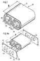
- FIG. 1 there is thus illustrated as an example the inlet 46 for the first fluid loop emphasised by black shading which extends in spiral form outwards from the centre of the first coil 32, over " the joint region " between the coils 32,34 and in spiral form inwards towards the centre of the other coil 34 and to the outlet 48.
- the inlet 50 for the second fluid loop illustrated in white which extends in spiral form outwards from the centre of the second coil 34, over " the joint region " between the coils 34,32 and so further in spiral form inwards towards the centre of the first coil 32 to the outlet 52.
- the heat exchanger will according to this example, function according to the counter-current principle.
- the two fluid streams can be adapted co-currently, in that the inlets to the two loops lie in the one coil half while the outlets from the loops lie in the other coil half.
- FIG. 8a and 8b is shown how there is added on each side surface of the heat exchanger a plate 60,70 with holes 62,64, 66,68 which are accurately adapted to the corresponding inlets/outlets 46,52,50,48.
- the plates are designed and adapted to the heat exchanger construction 10 so that they seal well up to the spiral-forming side edges of the band, so that any leakage between the fluid circuits does not occur.
- the heat exchanger is ready for the set of hoses or pipes to be coupled to the inlet 46 and the outlet 48 for axial supply and discharge respectively of a first in the first fluid loop, and also in order for the set of hoses or pipes to be coupled to the inlet 50 and the outlet 52 for supply and discharge respectively of a second fluid in the second fluid loop.
- the in/outlet regions by way of example lie on both sides of the heat exchanger, so that the fluid can be supplied and released from both sides.
- the one of the plates 60,70 can according to Figure 8a be without holes and covers the side edge of the heat exchanger completely so that the fluid is only supplied/discharged from the one side of the heat exchanger according to the desired arrangement.
- the axially directed inlets/outlets represent a larger area than the spiral loops.
- the axial inward and outward flow speed of a fluid (for example a liquid) can/will therefore be lower than the spiral fluid speed.
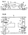
- Figures 9 and 10 show respectively a side section and a plan section of an apparatus 70 which is employed in the method for the production of the heat exchanger according to the invention.
- the apparatus comprises two parallel rails 72,74 arranged on a pedestal (not shown).
- Two separate and parallel travelling carriages 76,78 comprising cross-bars, are mounted at each of their ends on the two rails 72,74, The travelling carriages can be moved towards each other and away from each other on the rails 72,74.
- Each end of the travelling carriages is connected to the respective rail via a set of wheels (not shown further).
- the travelling carriages comprise a device which maintains a given band tension.
- a mounting unit or a holder 84,86 for the two pairs of rollers 18,20 and 14,16 respectively (cp. Figure 2) is connected to its respective travelling carriage 76,78 via a pedestal 80,82.
- the pairs of rollers 18,20 and 14,16 respectively are mounted to the mounting unit (the holder) 84,86 so that they are mutually parallel with each other and with the longitudinal direction of the travelling carriages.
- the pairs of rollers are further adapted to be conducted forwards and backwards in a direction along the longitudinal direction of the travelling carriages between a rest position 88 and a working position 90.
- the pedestal 80 with the roller mounting unit 84 is arranged at the end of the travelling carriage 76 which is adjacent to the first rail 74, while the other pedestal 82 with the associated roller mounting unit 86 is arranged at the end of the travelling carriage 78 which is adjacent to the second rail 72.
- Each unit 84,86 comprises a drive means 92,94 in the form of motors for rotation of the respective pairs of rollers 18,20 and 14,16 about a rotational axis 22a and 22b respectively ( Figure 9 and 10).
- the travelling carriages 80,82 have drive means, especially in the form of motors 91,93 connected to the wheels so that the travelling carriages can establish an outwardly directed force on the band and tighten up the latter, and further in order to provide a sufficient braking force on the carriages when these are moved towards each other during the coiling so that a predetermined tension is maintained in the band.
- Both the operation of the rotation drive means 92,94 for the cores and the motors 91,93 for driving the travelling carriages are connected into a data system so that the driving of these can be accurately controlled. The object of this is there shall be maintained a satisfactory tension in the. plate band loop during the coiling up of the heat exchanger.
- the apparatus according to the invention is applied to produce a heat exchanger of an elongate band-shaped plate the end edges. of which are joined to form an endless band 12.
- the band has a breadth equal to B.
- the respective pairs of rollers 18,20 and 14,16 are now conducted forwards viewed relatively towards each other from their rest position 88 to their working position 90.
- the band 12 is then installed in the gap between each roller of a pair of rollers so that the one roller 14,18 on each side is located within the loop, while the other is located outside.
- the travelling carriages 76,78 are now led away from each other so that the band is tightened up to a satisfactory tension.
- the upper stretch of plate band is arranged with an overlength corresponding to the height H as mentioned above. Now the clockwise/counterclockwise rotation of the respective roller pairs 18,20 and 14,16 about respective rotational axes 22a and 22b starts simultaneously.
- the travelling carriage device maintains the necessary band tension in that there is exerted a controlled braking effect via the motors 91,93 on the movement of the travelling carriages towards each other.
- the band is coiled up into two coils 32,34 as is shown in the Figures 2-7, of desired size. How many turns in spiral form the bands are coiled around the core rollers, depends upon the length of the band. During the coiling the band exerts a gradually increasing tightening around the rollers so that they will hardly be able to be extracted without their outer diameters being reduced when the coiling is finished. See Figure 11 which shows a mechanism with which such a diameter reduction can be carried out.
- the rollers are extracted and there is established a fluid-tight joint between the point of contact 36/44 of the coils 32,34, such as by welding, gluing or the like.
- the pairs of rollers are now drawn back, and the apparatus is ready for a new coiling process.
- Fig. 11 there is shown a construction for changing the diameter of the roller.
- the roller surface is formed of a number of elongate arcuate segments 94 which squeezed together form a sleeve having a uniformly cylindrical surface.
- Four such sections 94 are shown lowermost in Figure 11, and here they are outstretched in the position they have during the coiling.
- the sections are arranged around a roller axle 96 and are held in place peripherally around the axle by means of a number of peripherally extending annular springs, especially two springs 98,100, which are arranged each in its annular groove 97,99 recessed in the peripheral surface of the sections/rollers.
- the sections form a sleeve having a substantially circular cross-section.
- the inner end of the axle towards the unit 88 comprises conical surfaces 95.
- a removable end cap 102 comprises equivalent conical surfaces 104 on the inner end while its outer end forms an annular stopper flange 101.
- the cap is hollow, and comprises a transversely extending rod 110 which can be hooked into a hook-forming recessed groove 112 in the axle 96 of the roller.
- the cap is locked fixed to the axle 96 in that the cap is twisted and activates a bayonet coupling. Thereby the roller in its outer position is ready for the coiling process. After the coiling process the cap is loosened, the sections are drawn radially inwards so that the sleeve is loosened, and it can then be extracted from the finished heat exchanger.
- Figure 12 shows an alternative construction of the end plates according to Figure 8a,b.
- an end plate where the surface which is to be installed against end surfaces of the heat exchanger, comprises a hardenable material, such as plastic, rubber or epoxy.
- the sealing is ensured when the substance hardens. It is also possible to hold the end plates mutually together by means of through-going bolts so that the plates are pressed together against a packing of soft rubber/plastic.
- FIG. 13 A preferred construction is illustrated in Figure 13 in the form of hemispherical recesses 109 which are designed, for example by stamping, in a regular or irregular pattern in the plate band ahead of the coiling process.
- the Figure shows a partial cross-section of a finished heat exchanger with a number of such recesses in each plate formed by the continuous band.
- Figure 14 shows four alternative constructions of spacing elements between the plates.
- a construction is illustrated of a compact spacing element 112 of quadratic cross-section, a hollow element 114 of rectangular cross-section, a hollow element 116 of circular cross-section, or as an elongate spiral 118 in the form of a helical spring.
- the spacing elements can comprise smaller single bits (cubes) which are installed between the plates, or as long strands which are stitched to the surface of the band/plate in its longitudinal direction before the coiling starts. It can be sufficient to lay such a spacing element at each edge portion of the plate/band, or several rows of spacing elements between the plates, dependent on the breadth B of the place.
- the spacing element is preferably formed of an elongate helical spring which is placed (such as by being glued on) the band surfaces in the longitudinal direction of the band.
- a spring is especially favourable because it can be stretched both in the longitudinal direction and partially extended radially, and can thereby be bent and stretched in step with the bending of the band during coiling up.
- FIG. 15 shows a cross-section of a U-shaped profile strip 119 of rubber or plastic.
- a U-profile is placed so that the longitudinal side edge of the band lies down in the U-form.
- Such a U-profile strip of thickness X is mounted on the band edge over the full length of the latter before the coiling up.
- the U-shaped strips are thereby a combined element which both function as spacing element and as sealing means between the fluid loops.
- Figure 16 shows a construction where adjacent plate edges can be deflected towards each other, shown at 120, and welded so as to define the one fluid run after coiling up.
- a strip of rectangular profile can be arranged in a weldable material in the intermediate space between two band/plates, and welded in order thereby to seal the intermediate space.
- the heat exchanger can be made by extruding with an optional length, and which thereafter is cut to the desired. breadth, for example with the breadth B of Figure 1.
- the novel heat exchanger construction makes possible a new and flow-correct method for obtaining heat exchange between two fluids.
- flow-correct is meant in this connection that a fluid which is to emit heat to the other fluid, can utilise the length optimum of the novel heat exchanger, that is to say that by the countercurrent function the ingoing fluid meets the outgoing fluid in the region where the ingoing fluid starts the contact for the transfer of heat.
- the heat transfer effect can be very high, something which is confirmed by tests, but is obviously dependent upon the choice of material.
- the contact time between the two fluids can be extended with the new construction.
- the exchanger according to the invention can be arranged for the fluid-combinations gas/gas; gas/liquid; liquid/liquid.
- the two side plates 60,70 can, when they are screwed to side surfaces of the heat exchanger, be readily removed and one then gets access to the interior of the heat exchanger which thereby can be cleaned such as by flushing.
- heat exchanger can be used during processes where it is operated with heat exchanging (as a heat exchanger), settling, flotation, and separation, or for filtering, moistening/demoistening and drying.
Landscapes
- Engineering & Computer Science (AREA)
- Mechanical Engineering (AREA)
- Physics & Mathematics (AREA)
- Thermal Sciences (AREA)
- General Engineering & Computer Science (AREA)
- Heat-Exchange Devices With Radiators And Conduit Assemblies (AREA)
- Separation By Low-Temperature Treatments (AREA)
- Heating, Cooling, Or Curing Plastics Or The Like In General (AREA)
Claims (14)
- Wärmeaustauscher (10), umfassend zwei Platten (12), die eine gegebene Breite (B) und einen im wesentlichen konstanten Abstand (x) zueinander aufweisen und die in einer Spiralform um einen Achse (22) gewickelt sind, um zwei separate spiralartige Fluidschleifen zu bilden, deren jede zentrale axiale Öffnungen hat, die jeweils Einlässe oder Auslässe (48, 46, 50, 52) zu den beiden Fluidschleifen definieren, wobei die Anordnung zwei Austauschereinheiten (32, 34) mit zueinander spiegelbildlich orientierten Wicklungen um jeweilige Achsen umfasst, wobei die zwei äußeren Wicklungen (40, 42) der Platten der ersten Austauschereinheit mit den zwei äußeren Wicklungen (40, 42) der zweiten Austauschereinheit verbunden sind, um dadurch eine erste der beiden separaten Fluidschleifen zu bilden, und dadurch gekennzeichnet, dass sich die äußerste Wicklung (40) der ersten Austauschereinheit in Tangentiallinien- (36) oder Flächenkontakt (44) mit der äußersten Wicklung (40) der zweiten Austauschereinheit befindet, wobei eine fluiddichte Abdichtung in der Kontaktlinie oder ―fläche hergestellt wird, wodurch die zweite der beiden getrennten Fluidschleifen gebildet wird.
- Wärmeaustauscher nach Anspruch 1, dadurch gekennzeichnet, dass die beiden Austauschereinheiten eine gleiche oder verschiedene Anzahl von Wicklungen aufweisen.
- Wärmeaustauscher nach Anspruch 1 oder 2, dadurch gekennzeichnet, dass zwischen den Platten in an sich bekannter Weise eine Anzahl von Beabstandungselementen angeordnet ist, wie beispielsweise eine Anzahl von Ausnehmungen, die in einem regelmäßigen oder unregelmäßigen Muster in der Längsrichtung der Platten gestaltet sind, kubischen Körpern, Ianggestreckten Litzen und dergleichen, oder dass als Beabstandungselement eine flexible Schraubenfeder verwendet wird, die, während das Aufwickeln stattfindet, nach und nach zwischen den Platten eingeschlossen wird.
- Wärmeaustauscher nach Anspruch 1, dadurch gekennzeichnet, dass ein kombiniertes Beabstandungs- und Dichtungselement (119) zwischen den Fluidschleifen verwendet wird, speziell umfassend einen flexiblen Profilstreifen (119) mit U-förmigem Querschnitt, vorzugsweise aus Gummi oder Kunststoff, und das so installiert wird, dass die Längsseitenkante des gesamten Bandes unten in der U-Form liegt.
- Wärmeaustauscher nach Anspruch 1, gekennzeichnet durch ein kombiniertes Beabstandungs- und Dichtungselement in Form eines plattenförmigen Körpers (111), bei dem die bis zu den Seitenkanten des Wärmeaustauschers angeordnete Oberfläche eine Schicht (113) aus härtbarem Material wie Kunststoff, Gummi oder Epoxidharz umfasst.
- Wärmeaustauscher nach Anspruch 5, dadurch gekennzeichnet, dass ein dichtungsbildender plattenförmiger Körper (111) bis zu jeder gegenüberliegenden Seitenkante des Austauschers angeordnet ist, wo die Körper (111) mittels hindurchgehender Bolzen an die jeweiligen Seitenkanten angedrückt gehalten werden.
- Wärmeaustauscher nach Anspruch 1, dadurch gekennzeichnet, dass der Austauscher aus einem Kunststoffmaterial oder einem metallischen Material extrudiert ist.
- Verfahren zu Herstellung eines Wärmeaustauschers (10) nach einem der Ansprüche 1 bis 7, dadurch gekennzeichnet:dass eine bandförmige Platte (12) mit einer gegebenen Breite (B) Endkante and Endkante zusammengefügt wird, um ein Endlosband zu bilden;dass jedes Ende der bandförmigen Plattenschleife in einen Spalt (21, 22) zwischen zwei im wesentlichen parallelen länglichen Kernen (14, 16 bzw. 18, 20) eingeführt wird,dass zwei Paare von Kernen (14, 16 bzw. 18, 30) voneinander weggeführt werden, um das Band (12) zu verspannen,dass zwei Paare von Kernen (14, 16 bzw. 18, 20) gegeneinander um ihre Achsen (22a, 22b) gedreht werden, um so das Band (12) um zwei Kern-Paare (14, 16 bzw. 18, 20) zu wickeln, um zwei spiralförmige Wickel (32, 34) zu bilden, während die Kernpaare (14,16 bzw. 18, 20) gleichzeitig aufeinander zu bewegt werden, wobei in dem Band (12) eine im wesentlichen konstante Spannung beibehalten wird,dass in der Line (36) oder Oberfläche (44), wo die beiden Wickel einander kontaktieren, eine dichte Abdichtung hergestellt wird, unddass die beiden Kern-Paare (14, 16 bzw. 18, 20) aus den Wickeln (32, 34) herausgezogen werden.
- Verfahren nach Anspruch 8, dadurch gekennzeichnet, dass längliche Kerne (14, 16 bzw. 18, 20) verwendet werden, deren Durchmesser zwischen einem maximalen und einem minimalen Durchmesser einstellbar sind, wobei der minimale Durchmesser hergestellt wird, wenn die Kerne (14, 20 bzw. 18, 20) aus den Wickeln (32, 34) herauszuziehen sind.
- Vorrichtung zur Herstellung eines Wärmeaustauschers (10) in Spiralform, dadurch gekennzeichnet, dass sie umfasst:zwei Haltereinheiten (84, 86), deren jede ein Paar aus zueinander länglichen Kernen (14, 16 bzw. 18, 20) umfasst, die zwischen sich einen Spalt (21, 22) bilden, wobei die beiden Kern-Paare (14, 16 bzw. 18, 20) parallel zueinander sind, wobeijede Haltereinheit (84, 86) so ausgelegt ist, dass sie das jeweilige Paar (14, 16 und 18, 20) von Kernen um eine Achse dreht, die sich etwa parallel zu den Kernen durch den Spalt (21, 22) erstreckt, undMittel (92, 94) zum Bewegen der beiden Haltereinheiten in Richtung zueinander und weg voneinander.
- Vorrichtung nach Anspruch 10, dadurch gekennzeichnet, dass jeder Kern (14, 20 bzw. 18, 20) aus einer Rolle gebildet ist, deren Durchmesser zwischen einem maximalen Durchmesser und einem minimalen Durchmesser einstellbar ist.
- Vorrichtung nach Anspruch 10 - 11, dadurch gekennzeichnet, dass jede Haltereinheit (84, 86) mit einem Rahmen (76, 78), wie beispielsweise einem fahrbaren Schlitten, verbunden ist und dass der Rahmen über eine Radeinheit mit einer Schiene (72, 74) verbunden ist und
dass die Bewegung der beiden Halter durch eine Verschiebung des Rahmens/der Radeinheit (76, 78) entlang der Schiene (72, 74) erfolgt. - Vorrichtung nach Anspruch 12, gekennzeichnet durch
ein Mittel zum Regulieren der Bewegung der beiden Halter (84, 86) entlang der Schiene relativ zur Drehung der Kerne (14, 16 bzw. 18, 20), wobei das Mittel vorzugsweise ein Motor (91, 93) in Verbindung mit jedem fahrbaren Schlitten (76, 78) ist und die Bewegung der fahrbaren Schlitten (76, 78) entlang der Schiene (72, 74) steuert. - Vorrichtung nach Anspruch 11, gekennzeichnet durch
zwei voneinander getrennte parallele Schienen (72, 74), an denen jedes Ende der fahrbaren Schlitten (76, 78) jeweils beweglich montiert ist, wobei die Halter (84, 86) an den beiden fahrbaren Schlitten (76, 78) so angeordnet sind, dass sich die Kerne (14, 16 bzw. 18, 20) relativ gesehen in Richtung zueinander drehen.
Applications Claiming Priority (1)
| Application Number | Priority Date | Filing Date | Title |
|---|---|---|---|
| PCT/NO1998/000296 WO2000020817A1 (en) | 1998-10-02 | 1998-10-02 | Heat exchanger construction, method and apparatus for producing same, and use of the heat exchanger |
Publications (2)
| Publication Number | Publication Date |
|---|---|
| EP1125090A1 EP1125090A1 (de) | 2001-08-22 |
| EP1125090B1 true EP1125090B1 (de) | 2004-03-17 |
Family
ID=19907884
Family Applications (1)
| Application Number | Title | Priority Date | Filing Date |
|---|---|---|---|
| EP98959305A Expired - Lifetime EP1125090B1 (de) | 1998-10-02 | 1998-10-02 | Wärmetauscher, verfahren und vorrichtung zu dessen herstellung |
Country Status (5)
| Country | Link |
|---|---|
| EP (1) | EP1125090B1 (de) |
| AT (1) | ATE262154T1 (de) |
| AU (1) | AU1512899A (de) |
| DE (1) | DE69822523D1 (de) |
| WO (1) | WO2000020817A1 (de) |
Family Cites Families (9)
| Publication number | Priority date | Publication date | Assignee | Title |
|---|---|---|---|---|
| SE164229C1 (de) * | ||||
| NL39841C (de) * | 1934-06-27 | |||
| FR835161A (fr) * | 1937-03-12 | 1938-12-14 | échangeur de température | |
| GB745914A (en) * | 1953-01-28 | 1956-03-07 | William Helmore | Improvements in or relating to heat exchangers |
| FR1396469A (fr) * | 1964-03-11 | 1965-04-23 | échangeur de chaleur entre deux fluides | |
| DE3505789A1 (de) * | 1985-02-20 | 1986-08-21 | Grote, Paul, 2901 Friedrichsfehn | Spiralwaermetauscher |
| DE3509226C2 (de) * | 1985-03-14 | 1997-03-27 | Sen Alexander Faller | Wärmetauscher |
| FR2596144B1 (fr) * | 1986-03-24 | 1988-05-27 | Jouet Etienne | Echangeur de chaleur spirale et son procede de fabrication |
| DE4413867A1 (de) * | 1994-04-21 | 1995-10-26 | Paul Grote | Verfahren zur Herstellung eines rekuperativen Spiralwärmetauschers |
-
1998
- 1998-10-02 AT AT98959305T patent/ATE262154T1/de not_active IP Right Cessation
- 1998-10-02 AU AU15128/99A patent/AU1512899A/en not_active Abandoned
- 1998-10-02 DE DE69822523T patent/DE69822523D1/de not_active Expired - Lifetime
- 1998-10-02 WO PCT/NO1998/000296 patent/WO2000020817A1/en not_active Ceased
- 1998-10-02 EP EP98959305A patent/EP1125090B1/de not_active Expired - Lifetime
Also Published As
| Publication number | Publication date |
|---|---|
| AU1512899A (en) | 2000-04-26 |
| DE69822523D1 (de) | 2004-04-22 |
| WO2000020817A1 (en) | 2000-04-13 |
| ATE262154T1 (de) | 2004-04-15 |
| EP1125090A1 (de) | 2001-08-22 |
Similar Documents
| Publication | Publication Date | Title |
|---|---|---|
| US5885454A (en) | Separation module and bundle unit of hollow thread-type porous membrane elements and methods of producing same | |
| US7591933B2 (en) | Spiral electrodeionization device with segregated ionic flows | |
| US4451960A (en) | Method of producing multiple coil, multiple tube heat exchanger | |
| EP2217346B1 (de) | Filterelement mit einem wickelkern mit einer in mindestens einer seite davon ausgebildeten druckentlastungskerbe | |
| AU2009303747B2 (en) | Spirally wound membrane separator assembly | |
| KR860000805B1 (ko) | 주름진 튜우브의 제조방법 및 장치 | |
| EP2106281B1 (de) | Fluidfiltervorrichtung mit um einen wickelrahmen gewickelten filtermedien | |
| EP0562520B1 (de) | Verfahren zur Herstellung von Hohlfasermembranbund | |
| MXPA04001015A (es) | Procedimiento de fabricacion y aparato para hacer un tubo con costillas helicoidales. | |
| WO2010044971A1 (en) | Central core element for a spirally wound separator assembly | |
| CA1128497A (en) | Tube sheet accommodating differential expansion | |
| US9757676B2 (en) | Method and apparatus for winding a filter element | |
| IE43442B1 (en) | Apparatus with supported tubular membranes for the treatment of fluids | |
| US7306709B2 (en) | Spiral electrodeionization device with flow distribution profiling | |
| SU812158A3 (ru) | Способ изготовлени многослойныхиздЕлий и уСТРОйСТВО дл ЕгООСущЕСТВлЕНи | |
| WO2000020817A1 (en) | Heat exchanger construction, method and apparatus for producing same, and use of the heat exchanger | |
| SE434343B (sv) | Forfarande for tillverkning av moduler av ihaliga filament, for omvend osmos och liknande | |
| US20070245790A1 (en) | Canasta for Forming Tubes of Different Diameters | |
| EP0206629B1 (de) | Siebe sowie Verfahren und Vorrichtung zu deren Herstellung | |
| EP0053604B1 (de) | Verfahren zur herstellung eines wärmetauschers mit mehreren rohren und wickelungen | |
| CA2354405A1 (en) | Conduit-making apparatus with a variable-diameter winding drum | |
| SU1354027A1 (ru) | Ороситель градирни | |
| JP2010522072A (ja) | 流体処理エレメントを備える流体処理装置及び流体処理装置を製造し使用するための方法 | |
| US5437819A (en) | Fluid contacting apparatus and methods of making the same | |
| CN120838179B (zh) | 一种卷式扩散渗析膜组件及其制备方法 |
Legal Events
| Date | Code | Title | Description |
|---|---|---|---|
| PUAI | Public reference made under article 153(3) epc to a published international application that has entered the european phase |
Free format text: ORIGINAL CODE: 0009012 |
|
| 17P | Request for examination filed |
Effective date: 20010502 |
|
| AK | Designated contracting states |
Kind code of ref document: A1 Designated state(s): AT BE CH CY DE DK ES FI FR GB GR IE IT LI LU MC NL PT SE |
|
| 17Q | First examination report despatched |
Effective date: 20020627 |
|
| RTI1 | Title (correction) |
Free format text: HEAT EXCHANGER, METHOD AND APPARATUS FOR PRODUCING SAME, AND USE OF THE HEAT EXCHANGER |
|
| RTI1 | Title (correction) |
Free format text: HEAT EXCHANGER, METHOD AND APPARATUS FOR PRODUCING SAME |
|
| GRAP | Despatch of communication of intention to grant a patent |
Free format text: ORIGINAL CODE: EPIDOSNIGR1 |
|
| GRAS | Grant fee paid |
Free format text: ORIGINAL CODE: EPIDOSNIGR3 |
|
| GRAA | (expected) grant |
Free format text: ORIGINAL CODE: 0009210 |
|
| AK | Designated contracting states |
Kind code of ref document: B1 Designated state(s): AT BE CH CY DE DK ES FI FR GB GR IE IT LI LU MC NL PT SE |
|
| PG25 | Lapsed in a contracting state [announced via postgrant information from national office to epo] |
Ref country code: NL Free format text: LAPSE BECAUSE OF FAILURE TO SUBMIT A TRANSLATION OF THE DESCRIPTION OR TO PAY THE FEE WITHIN THE PRESCRIBED TIME-LIMIT Effective date: 20040317 Ref country code: LI Free format text: LAPSE BECAUSE OF FAILURE TO SUBMIT A TRANSLATION OF THE DESCRIPTION OR TO PAY THE FEE WITHIN THE PRESCRIBED TIME-LIMIT Effective date: 20040317 Ref country code: IT Free format text: LAPSE BECAUSE OF FAILURE TO SUBMIT A TRANSLATION OF THE DESCRIPTION OR TO PAY THE FEE WITHIN THE PRE;WARNING: LAPSES OF ITALIAN PATENTS WITH EFFECTIVE DATE BEFORE 2007 MAY HAVE OCCURRED AT ANY TIME BEFORE 2007. THE CORRECT EFFECTIVE DATE MAY BE DIFFERENT FROM THE ONE RECORDED.SCRIBED TIME-LIMIT Effective date: 20040317 Ref country code: FR Free format text: LAPSE BECAUSE OF FAILURE TO SUBMIT A TRANSLATION OF THE DESCRIPTION OR TO PAY THE FEE WITHIN THE PRESCRIBED TIME-LIMIT Effective date: 20040317 Ref country code: FI Free format text: LAPSE BECAUSE OF FAILURE TO SUBMIT A TRANSLATION OF THE DESCRIPTION OR TO PAY THE FEE WITHIN THE PRESCRIBED TIME-LIMIT Effective date: 20040317 Ref country code: CY Free format text: LAPSE BECAUSE OF FAILURE TO SUBMIT A TRANSLATION OF THE DESCRIPTION OR TO PAY THE FEE WITHIN THE PRESCRIBED TIME-LIMIT Effective date: 20040317 Ref country code: CH Free format text: LAPSE BECAUSE OF FAILURE TO SUBMIT A TRANSLATION OF THE DESCRIPTION OR TO PAY THE FEE WITHIN THE PRESCRIBED TIME-LIMIT Effective date: 20040317 Ref country code: BE Free format text: LAPSE BECAUSE OF FAILURE TO SUBMIT A TRANSLATION OF THE DESCRIPTION OR TO PAY THE FEE WITHIN THE PRESCRIBED TIME-LIMIT Effective date: 20040317 Ref country code: AT Free format text: LAPSE BECAUSE OF FAILURE TO SUBMIT A TRANSLATION OF THE DESCRIPTION OR TO PAY THE FEE WITHIN THE PRESCRIBED TIME-LIMIT Effective date: 20040317 |
|
| REG | Reference to a national code |
Ref country code: GB Ref legal event code: FG4D |
|
| REG | Reference to a national code |
Ref country code: CH Ref legal event code: EP |
|
| REG | Reference to a national code |
Ref country code: IE Ref legal event code: FG4D |
|
| REF | Corresponds to: |
Ref document number: 69822523 Country of ref document: DE Date of ref document: 20040422 Kind code of ref document: P |
|
| PG25 | Lapsed in a contracting state [announced via postgrant information from national office to epo] |
Ref country code: GR Free format text: LAPSE BECAUSE OF FAILURE TO SUBMIT A TRANSLATION OF THE DESCRIPTION OR TO PAY THE FEE WITHIN THE PRESCRIBED TIME-LIMIT Effective date: 20040617 Ref country code: DK Free format text: LAPSE BECAUSE OF FAILURE TO SUBMIT A TRANSLATION OF THE DESCRIPTION OR TO PAY THE FEE WITHIN THE PRESCRIBED TIME-LIMIT Effective date: 20040617 |
|
| PG25 | Lapsed in a contracting state [announced via postgrant information from national office to epo] |
Ref country code: DE Free format text: LAPSE BECAUSE OF FAILURE TO SUBMIT A TRANSLATION OF THE DESCRIPTION OR TO PAY THE FEE WITHIN THE PRESCRIBED TIME-LIMIT Effective date: 20040618 |
|
| PG25 | Lapsed in a contracting state [announced via postgrant information from national office to epo] |
Ref country code: ES Free format text: LAPSE BECAUSE OF FAILURE TO SUBMIT A TRANSLATION OF THE DESCRIPTION OR TO PAY THE FEE WITHIN THE PRESCRIBED TIME-LIMIT Effective date: 20040628 |
|
| REG | Reference to a national code |
Ref country code: SE Ref legal event code: TRGR |
|
| NLV1 | Nl: lapsed or annulled due to failure to fulfill the requirements of art. 29p and 29m of the patents act | ||
| REG | Reference to a national code |
Ref country code: CH Ref legal event code: PL |
|
| PG25 | Lapsed in a contracting state [announced via postgrant information from national office to epo] |
Ref country code: LU Free format text: LAPSE BECAUSE OF NON-PAYMENT OF DUE FEES Effective date: 20041002 Ref country code: GB Free format text: LAPSE BECAUSE OF NON-PAYMENT OF DUE FEES Effective date: 20041002 |
|
| PG25 | Lapsed in a contracting state [announced via postgrant information from national office to epo] |
Ref country code: IE Free format text: LAPSE BECAUSE OF NON-PAYMENT OF DUE FEES Effective date: 20041004 |
|
| PG25 | Lapsed in a contracting state [announced via postgrant information from national office to epo] |
Ref country code: MC Free format text: LAPSE BECAUSE OF NON-PAYMENT OF DUE FEES Effective date: 20041031 |
|
| PLBE | No opposition filed within time limit |
Free format text: ORIGINAL CODE: 0009261 |
|
| STAA | Information on the status of an ep patent application or granted ep patent |
Free format text: STATUS: NO OPPOSITION FILED WITHIN TIME LIMIT |
|
| EN | Fr: translation not filed | ||
| 26N | No opposition filed |
Effective date: 20041220 |
|
| GBPC | Gb: european patent ceased through non-payment of renewal fee |
Effective date: 20041002 |
|
| REG | Reference to a national code |
Ref country code: IE Ref legal event code: MM4A |
|
| PG25 | Lapsed in a contracting state [announced via postgrant information from national office to epo] |
Ref country code: PT Free format text: LAPSE BECAUSE OF NON-PAYMENT OF DUE FEES Effective date: 20040817 |
|
| PGFP | Annual fee paid to national office [announced via postgrant information from national office to epo] |
Ref country code: SE Payment date: 20100928 Year of fee payment: 13 |
|
| REG | Reference to a national code |
Ref country code: SE Ref legal event code: EUG |
|
| PG25 | Lapsed in a contracting state [announced via postgrant information from national office to epo] |
Ref country code: SE Free format text: LAPSE BECAUSE OF NON-PAYMENT OF DUE FEES Effective date: 20111003 |