EP1125313B1 - Metallhalogenidlampe - Google Patents
Metallhalogenidlampe Download PDFInfo
- Publication number
- EP1125313B1 EP1125313B1 EP00958399A EP00958399A EP1125313B1 EP 1125313 B1 EP1125313 B1 EP 1125313B1 EP 00958399 A EP00958399 A EP 00958399A EP 00958399 A EP00958399 A EP 00958399A EP 1125313 B1 EP1125313 B1 EP 1125313B1
- Authority
- EP
- European Patent Office
- Prior art keywords
- ceramic
- lamp
- lead
- discharge vessel
- strip
- Prior art date
- Legal status (The legal status is an assumption and is not a legal conclusion. Google has not performed a legal analysis and makes no representation as to the accuracy of the status listed.)
- Expired - Lifetime
Links
- 229910001507 metal halide Inorganic materials 0.000 title claims abstract description 5
- 150000005309 metal halides Chemical class 0.000 title claims abstract description 5
- 239000000919 ceramic Substances 0.000 claims abstract description 57
- 239000002184 metal Substances 0.000 claims abstract description 24
- 229910052751 metal Inorganic materials 0.000 claims abstract description 24
- 238000007789 sealing Methods 0.000 claims abstract description 23
- 239000004020 conductor Substances 0.000 claims abstract description 10
- 150000004820 halides Chemical class 0.000 description 10
- 238000004519 manufacturing process Methods 0.000 description 8
- 238000010276 construction Methods 0.000 description 7
- 239000011888 foil Substances 0.000 description 5
- PNEYBMLMFCGWSK-UHFFFAOYSA-N aluminium oxide Inorganic materials [O-2].[O-2].[O-2].[Al+3].[Al+3] PNEYBMLMFCGWSK-UHFFFAOYSA-N 0.000 description 2
- 229910052593 corundum Inorganic materials 0.000 description 2
- 230000002349 favourable effect Effects 0.000 description 2
- 238000007689 inspection Methods 0.000 description 2
- 239000000463 material Substances 0.000 description 2
- 229910001845 yogo sapphire Inorganic materials 0.000 description 2
- 229910052684 Cerium Inorganic materials 0.000 description 1
- 229910052692 Dysprosium Inorganic materials 0.000 description 1
- 239000000853 adhesive Substances 0.000 description 1
- 230000001070 adhesive effect Effects 0.000 description 1
- 229910010293 ceramic material Inorganic materials 0.000 description 1
- -1 for example Chemical class 0.000 description 1
- 239000011521 glass Substances 0.000 description 1
- 238000002844 melting Methods 0.000 description 1
- 230000008018 melting Effects 0.000 description 1
- 229910052753 mercury Inorganic materials 0.000 description 1
- 229910044991 metal oxide Inorganic materials 0.000 description 1
- 150000004706 metal oxides Chemical class 0.000 description 1
- 150000004767 nitrides Chemical class 0.000 description 1
- 230000002028 premature Effects 0.000 description 1
- 229910052594 sapphire Inorganic materials 0.000 description 1
- 239000010980 sapphire Substances 0.000 description 1
Images

Classifications
-
- H—ELECTRICITY
- H01—ELECTRIC ELEMENTS
- H01J—ELECTRIC DISCHARGE TUBES OR DISCHARGE LAMPS
- H01J61/00—Gas-discharge or vapour-discharge lamps
- H01J61/02—Details
- H01J61/36—Seals between parts of vessels; Seals for leading-in conductors; Leading-in conductors
- H01J61/366—Seals for leading-in conductors
Definitions
- the invention relates to a metal halide lamp provided with a discharge vessel with a ceramic wall which encloses a discharge space in which an electrode is arranged, which discharge vessel space is sealed off by means of a ceramic plug in which a lead-through element is fastened in a gastight manner by means of a sealing ceramic, said lead-through element serving to form an electrical connection between the electrode and a conductor outside the discharge vessel.
- ceramic wall in the present description and claims is understood to mean a wall of metal oxide such as, for example, sapphire or densely sintered polycrystalline Al 2 O 3 as well as of metal nitride, for example A1N.
- the lead-through element in the known lamp is built up from at least two electrically conducting parts.
- the lead-through element consists of an Nb rod at the area of the ceramic seal.
- the advantage of the use of Nb is that it is highly ductile on the one hand, while on the other hand it has a coefficient of expansion which differs only very slightly from that of the ceramic material used for the discharge vessel.
- a disadvantage is, however, that Nb is not resistant to halides.
- the lead-through element in the known lamp comprises at least a second part which can be exposed to halides during a longer period, and that the Nb must be fully screened off from the discharge space, for example in that it is coated with the sealing ceramic.
- the second part which is allowed to be exposed to halides will have a coefficient of expansion which differs considerably from that of the ceramic wall material.
- a further disadvantage is found to occur in practice in the form of an attack on the sealing ceramic by the halide present, so that after some time the Nb comes into direct contact with the halides after all and the lamp fails prematurely.
- GB 1435244 discloses a lamp in which a foil is sintered as a lead-through conductor between an end of a ceramic wall of a discharge lamp and a ceramic closing disc.
- a lamp is known from US 4277715 in which a closed coiled foil extends as a lead-through conductor through an end plug of a discharge vessel from the interior to outside the discharge vessel, connected thereto by means of melting glass.
- the foil is provided around a ceramic rod.
- a disadvantage of such a coiled foil is that it is found to be practically impossible to keep the foil correctly positioned during lamp manufacture, so that a non-hermetic seal is obtained at the area of the lead-through conductor.
- the invention has for its object to provide a lamp of the kind mentioned in the opening paragraph which is of a simple construction and in which the risk of a premature failure owing to halide attacks is counteracted.
- a lamp of the kind mentioned in the opening paragraph is for this purpose characterized in that the lead-through element comprises a ceramic core which is connected in a gastight manner to the ceramic plug by means of sealing ceramic in a direct joint and which is provided with metal envelopes on either side of the direct joint, which metal envelopes are interconnected by means of a strip-shaped connecting part.
- An advantage of the lamp according to the invention is that the gastight closure with sealing ceramic is achieved as a direct joint between the ceramic wall and the ceramic core of the lead-through element. It is surprisingly found that the strip-shaped connecting part is entirely enveloped by the sealing ceramic while achieving a permanent adhesion and has no appreciable influence on the permanence of the lead-through construction, and thus on lamp life. A problem relating to the difference in coefficient of expansion is avoided in this manner.
- the strip-shaped connecting part is provided with knife edges. This is found to promote strongly a good and permanent adhesion between the sealing ceramic and the strip-shaped connecting part.
- the metal envelope is fastened to the ceramic core by means of sealing ceramic outside the discharge vessel.
- the metal envelopes are interconnected on either side of the direct joint by means of two strip-shaped connecting parts.
- One of the advantages of this is an improved stiffness of the assembly of the metal parts which form the envelopes and connecting strips in the finished lamp. This is of major importance for a fast and reliable mass production of the lamp.
- the two strip-shaped connecting parts are positioned diametrically opposite one another. This achieves both an optimum stiffness and an equally divided load on the lead-through in the operational state of the lamp.
- the metal envelopes and their strip-shaped connecting parts are made of Mo, because this was found to be suitable as an electrical conductor as well as highly resistant to halides.
- the strip-shaped connecting parts have a joint width B of at least 0.25 O and at most 0.34 O, O being the circumference of one of the envelopes. Such a width is found to be an optimum for realizing on the one hand a good current conduction and a good stiffness of the assembly of the metal parts which form the envelopes and connecting strips in the finished lamp, and on the other hand is still small enough not to detract from the permanence of the gastight sealing of the lead-through construction.
- the thickness of the envelopes and the strip-shaped connecting parts lies between 10 ⁇ m and 200 ⁇ m. Given such a choice of thickness, it was found to be possible to manufacture the entire assembly of envelopes and strip-shaped connecting parts from a pipe- or tube-shaped material, whereupon this can be passed over the ceramic core in a simple manner. A greater thickness increases the risk that the permanence of the lead-through construction becomes less reliable owing to the difference in coefficient of expansion.
- the sealing ceramic For realizing a good useful life of the gastight seal, it is desirable for the sealing ceramic to extend over a length of a few mm, preferably at least 3 mm, inside the ceramic plug. It is favorable when the sealing ceramic extends to over the metal envelope present in the ceramic plug, in particular if the lamp has small dimensions.
- An additional advantage of the lamp according to the invention is that the use of Nb is not necessary for current conduction outside the discharge vessel. This offers the possibility of operating the discharge vessel in the air.
- the metal envelopes on either side of the direct joint may have mutually different lengths. It is favorable, however, for reasons of production efficiency if the metal envelopes have the same length.
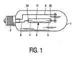
- Fig. 1 shows a metal halide lamp provided with a discharge vessel 3, which is shown in cross-section in Fig. 2 not true to scale, with a ceramic wall 31 which encloses a discharge space 11 containing an ionizable filling, comprising Hg, a quantity of Na halide, as well as T1, Dy, and Ce halides in the case shown.
- Two electrodes 4, 5, made of W in the drawing, with electrode rods 4a, 5a and electrode tips 4b, 5b with a mutual interspacing EA are arranged in the discharge space.
- the discharge vessel has an internal diameter Di at least over the distance EA.
- the discharge vessel is closed off at one side by means of a ceramic plug in the form of a projecting plug 34, 35, in which a lead-through element 40, 50 is fastened in a gastight manner by means of a sealing ceramic 10, said element serving to provide an electrical connection between the electrode and a conductor outside the discharge vessel.
- the lead-through element 40, 50 comprises a ceramic core 41, 51 which is connected in a gastight manner to the ceramic plug in a direct joint by means of the sealing ceramic 10 and which is provided with respective metal envelopes 42, 43 and 52, 53 on either side of the direct joint, which metal envelopes are interconnected by means of respective strip-shaped connecting parts 44 and 54.
- the metal envelope 42, 52 outside the discharge vessel is fastened to the ceramic core 41, 51 by means of the sealing ceramic 10.
- the strip-shaped connecting part 44, 54 is provided with knife edges 440, 540.
- the electrode rod 4a, 5a is connected to the metal envelope 43, 53 inside the discharge vessel with electrical conduction, for example by means of a spot
- the sealing ceramic extends over a length of approximately 4 mm inside the ceramic plug to over the metal envelope 43, 53 which is present in the ceramic plug.
- the discharge vessel is surrounded by an outer bulb 1 which is provided with a lamp cap 2 at an end.
- a discharge extends between the electrodes 4 and 5 in the operational state of the lamp.
- the electrode 4 is connected to a first electrical contact which forms part of the lamp cap 2 via a current conductor 8.
- the electrode 5 is connected to a second electrical contact which forms part of the lamp cap 2 via a current conductor 9.
- the lamp is of the CDM 70 type with a power rating of 70 W.
- the discharge vessel is closed off at both ends by means of a ceramic plug having an internal diameter of 780 ⁇ m.
- the lead-through element which is fastened in a direct joint in the plug by means of sealing ceramic comprises a ceramic core of Al 2 O 3 with a diameter of 450 ⁇ m which is provided with an Mo envelope at either end.
- the Mo envelope has an external diameter of 720 ⁇ m.
- the two envelopes are interconnected by two Mo strips. Each strip has a width of 340 ⁇ m, which means that in total for both strips this accounts for approximately 1/3 of the circumference of the envelopes.
- the envelope outside the discharge vessel and the one present in the ceramic plug each have a length of 7 mm.
- the thickness of the strips and of the two envelopes is 110 ⁇ m, their length is 5 mm.
- the lamp described was switched off for inspection purposes after it had reached a life of 6000 hours of operation.
- the inspection showed that the sealing ceramic was slightly attacked at its surface facing the discharge space, but only such that the entirety of the lead-through element, the ceramic plug and the gastight interconnection was intact.
Landscapes
- Vessels And Coating Films For Discharge Lamps (AREA)
Claims (7)
- Halogenmetalldampflampe, die mit einem Entladungsgefäß mit einer Keramikwandung (31) versehen ist, das einen Entladungsraum (30) umschließt, in dem eine Elektrode (4, 5) angeordnet ist, welches Entladungsgefäß mit einem Keramikstopfen (34, 35), verschlossen ist, in dem ein Durchführungselement (40, 50) mittels einer Schmelzkeramik (10) gasdicht befestigt ist, welches Durchführungselement dazu dient, eine elektrische Verbindung zwischen der Elektrode und einem Leiter außerhalb des Entladungsgefäßes zu bilden, dadurch gekennzeichnet, dass das Durchführungselement einen Keramikkern (41,51) umfasst, der mittels einer Schmelzkeramik in einer direkten Verbindung gasdicht mit dem Keramikstopfen verbunden ist und der zu beiden Seiten der direkten Verbindung mit Metall-Umhüllungen (42, 43, 52, 53) versehen ist, welche Metall-Umhüllungen mittels eines streifenförmigen Verbindungsteils (44, 54) miteinander verbunden sind.
- Lampe nach Anspruch 1, dadurch gekennzeichnet, dass das streifenförmige Verbindungsteil mit messerförmigen Kanten versehen ist.
- Lampe nach Anspruch 1 oder 2, dadurch gekennzeichnet, dass die Metall-Umhüllung außerhalb des Entladungsgefäßes mit Schmelzkeramik an dem Keramikkem befestigt ist.
- Lampe nach Anspruch 1, 2 oder 3, dadurch gekennzeichnet, dass die Metall-Umhüllungen zu beiden Seiten der direkten Verbindung mittels zweier streifenförmiger Verbindungsteile miteinander verbunden sind.
- Lampe nach Anspruch 4, dadurch gekennzeichnet, dass die zwei streifenförmigen Verbindungsteile einander diametral entgegengesetzt positioniert sind.
- Lampe nach Anspruch 1, 2, 3, 4 oder 5, dadurch gekennzeichnet, dass die Metall-Umhüllungen und ihre streifenförmigen Verbindungsteile aus Mo hergestellt sind.
- Lampe nach Anspruch 1, 2, 3, 4, 5 oder 6, dadurch gekennzeichnet, dass die streifenförmigen Verbindungsteile zusammen eine Breite B haben, die die Beziehung 0,25 O ≤ B ≤ 0,34 O erfüllt, wobei O der Umfang einer der Umhüllungen ist.
Priority Applications (1)
| Application Number | Priority Date | Filing Date | Title |
|---|---|---|---|
| EP00958399A EP1125313B1 (de) | 1999-08-31 | 2000-08-07 | Metallhalogenidlampe |
Applications Claiming Priority (4)
| Application Number | Priority Date | Filing Date | Title |
|---|---|---|---|
| EP99202815 | 1999-08-31 | ||
| EP99202815 | 1999-08-31 | ||
| EP00958399A EP1125313B1 (de) | 1999-08-31 | 2000-08-07 | Metallhalogenidlampe |
| PCT/EP2000/007690 WO2001016994A1 (en) | 1999-08-31 | 2000-08-07 | Metal halide lamp |
Publications (2)
| Publication Number | Publication Date |
|---|---|
| EP1125313A1 EP1125313A1 (de) | 2001-08-22 |
| EP1125313B1 true EP1125313B1 (de) | 2004-12-08 |
Family
ID=8240587
Family Applications (1)
| Application Number | Title | Priority Date | Filing Date |
|---|---|---|---|
| EP00958399A Expired - Lifetime EP1125313B1 (de) | 1999-08-31 | 2000-08-07 | Metallhalogenidlampe |
Country Status (6)
| Country | Link |
|---|---|
| US (1) | US6583562B1 (de) |
| EP (1) | EP1125313B1 (de) |
| JP (1) | JP2003508884A (de) |
| CN (1) | CN1216400C (de) |
| DE (1) | DE60016557T2 (de) |
| WO (1) | WO2001016994A1 (de) |
Families Citing this family (6)
| Publication number | Priority date | Publication date | Assignee | Title |
|---|---|---|---|---|
| US6774547B1 (en) | 2003-06-26 | 2004-08-10 | Osram Sylvania Inc. | Discharge lamp having a fluted electrical feed-through |
| CN100361266C (zh) * | 2003-09-11 | 2008-01-09 | 俞鹤庆 | 单晶氧化铝瓷高强度气体放电灯管 |
| DE102004001176A1 (de) * | 2004-01-05 | 2005-08-04 | Schott Ag | Verwendungen von Glaskeramiken |
| JP4772050B2 (ja) * | 2004-06-14 | 2011-09-14 | コーニンクレッカ フィリップス エレクトロニクス エヌ ヴィ | セラミックメタルハライド放電ランプ |
| US7759871B2 (en) * | 2005-12-16 | 2010-07-20 | General Electric Company | High temperature seal for electric lamp |
| US7619350B2 (en) * | 2006-08-29 | 2009-11-17 | Osram Sylvania Inc. | Arc discharge vessel having arc centering structure and lamp containing same |
Family Cites Families (12)
| Publication number | Priority date | Publication date | Assignee | Title |
|---|---|---|---|---|
| US2682009A (en) * | 1952-12-31 | 1954-06-22 | Westinghouse Electric Corp | Seal and method of fabrication |
| US2876377A (en) * | 1955-09-01 | 1959-03-03 | Westinghouse Electric Corp | Ribbon seal and method of fabrication |
| US3515929A (en) * | 1968-01-24 | 1970-06-02 | Westinghouse Electric Corp | Short arc lamp seal |
| US3793615A (en) * | 1970-11-04 | 1974-02-19 | Gen Electric | Oxidation-resistant lead-in conductors for electrical devices |
| NL7311290A (nl) * | 1973-08-16 | 1975-02-18 | Philips Nv | Werkwijze voor het afsluiten van een ontladings- |
| US3848151A (en) * | 1973-10-23 | 1974-11-12 | Gen Electric | Ceramic envelope lamp having metal foil inleads |
| NL7612120A (nl) * | 1976-11-02 | 1978-05-05 | Philips Nv | Elektrische gasontladingslamp. |
| CN1005176B (zh) * | 1985-04-09 | 1989-09-13 | 菲利普白炽灯有限公司 | 电灯 |
| DE69329046T2 (de) | 1992-09-08 | 2001-03-29 | Koninklijke Philips Electronics N.V., Eindhoven | Hochdruckentladungslampe |
| DE4242123A1 (de) * | 1992-12-14 | 1994-06-16 | Patent Treuhand Ges Fuer Elektrische Gluehlampen Mbh | Hochdruckentladungslampe mit einem keramischen Entladungsgefäß |
| US6169366B1 (en) * | 1997-12-24 | 2001-01-02 | Ngk Insulators, Ltd. | High pressure discharge lamp |
| JP3397145B2 (ja) * | 1998-09-18 | 2003-04-14 | ウシオ電機株式会社 | セラミック製ランプ |
-
2000
- 2000-08-07 JP JP2001520447A patent/JP2003508884A/ja not_active Abandoned
- 2000-08-07 EP EP00958399A patent/EP1125313B1/de not_active Expired - Lifetime
- 2000-08-07 WO PCT/EP2000/007690 patent/WO2001016994A1/en not_active Ceased
- 2000-08-07 DE DE60016557T patent/DE60016557T2/de not_active Expired - Fee Related
- 2000-08-07 CN CN00801832.4A patent/CN1216400C/zh not_active Expired - Fee Related
- 2000-08-29 US US09/649,935 patent/US6583562B1/en not_active Expired - Fee Related
Also Published As
| Publication number | Publication date |
|---|---|
| CN1321328A (zh) | 2001-11-07 |
| EP1125313A1 (de) | 2001-08-22 |
| JP2003508884A (ja) | 2003-03-04 |
| US6583562B1 (en) | 2003-06-24 |
| DE60016557D1 (de) | 2005-01-13 |
| WO2001016994A1 (en) | 2001-03-08 |
| DE60016557T2 (de) | 2005-12-15 |
| CN1216400C (zh) | 2005-08-24 |
Similar Documents
| Publication | Publication Date | Title |
|---|---|---|
| US6528945B2 (en) | Seal for ceramic metal halide discharge lamp | |
| JP2010192464A (ja) | 高圧放電ランプ | |
| US3693007A (en) | Oxide cathode for an electric discharge device | |
| EP0272930B1 (de) | Keramischer Kolben für Hochdruckentladungslampe | |
| JP2008124037A (ja) | 高圧放電ランプ | |
| EP1125313B1 (de) | Metallhalogenidlampe | |
| EP0971043B1 (de) | Cermet und keramische Entladungslampe | |
| EP0160445B1 (de) | Entladungsröhrenanordnung für Hochdruckentladungslampe | |
| JP2004528694A (ja) | セラミックメタルハライドランプ | |
| US4721886A (en) | High-pressure discharge lamp with precision end seal structure | |
| US6856079B1 (en) | Ceramic discharge lamp arc tube seal | |
| EP1014423B1 (de) | Metalldampfentladungslampe | |
| CN101288147A (zh) | 高压放电灯 | |
| JPH0519255B2 (de) | ||
| JP2003509813A (ja) | 金網を有するフィードスルーを具えるランプ | |
| US7164232B2 (en) | Seal for ceramic discharge lamp arc tube | |
| JP3438348B2 (ja) | 端子構造 | |
| GB2191337A (en) | A process for sealing the ceramic envelope of a high pressure discharge lamp, especially a sodium lamp, and a lamp made by this process | |
| JPS6329942B2 (de) | ||
| EP1080484B1 (de) | Elektrische lampe | |
| EP0100091A2 (de) | Keramische Versieglung für Natriumdampfhochdrucklampen | |
| JP2002533873A (ja) | ランプ | |
| JPH0327329Y2 (de) | ||
| CA1218690A (en) | Ceramic seal for high pressure sodium vapor lamps | |
| SU1024995A1 (ru) | Газоразр дна лампа |
Legal Events
| Date | Code | Title | Description |
|---|---|---|---|
| PUAI | Public reference made under article 153(3) epc to a published international application that has entered the european phase |
Free format text: ORIGINAL CODE: 0009012 |
|
| AK | Designated contracting states |
Kind code of ref document: A1 Designated state(s): AT BE CH CY DE DK ES FI FR GB GR IE IT LI LU MC NL PT SE |
|
| AX | Request for extension of the european patent |
Free format text: AL;LT;LV;MK;RO;SI |
|
| 17P | Request for examination filed |
Effective date: 20010910 |
|
| GRAP | Despatch of communication of intention to grant a patent |
Free format text: ORIGINAL CODE: EPIDOSNIGR1 |
|
| GRAS | Grant fee paid |
Free format text: ORIGINAL CODE: EPIDOSNIGR3 |
|
| GRAA | (expected) grant |
Free format text: ORIGINAL CODE: 0009210 |
|
| AK | Designated contracting states |
Kind code of ref document: B1 Designated state(s): BE DE FR GB |
|
| REG | Reference to a national code |
Ref country code: GB Ref legal event code: FG4D |
|
| REG | Reference to a national code |
Ref country code: IE Ref legal event code: FG4D |
|
| REF | Corresponds to: |
Ref document number: 60016557 Country of ref document: DE Date of ref document: 20050113 Kind code of ref document: P |
|
| PGFP | Annual fee paid to national office [announced via postgrant information from national office to epo] |
Ref country code: BE Payment date: 20050727 Year of fee payment: 6 |
|
| PGFP | Annual fee paid to national office [announced via postgrant information from national office to epo] |
Ref country code: FR Payment date: 20050812 Year of fee payment: 6 |
|
| PGFP | Annual fee paid to national office [announced via postgrant information from national office to epo] |
Ref country code: GB Payment date: 20050830 Year of fee payment: 6 |
|
| PLBE | No opposition filed within time limit |
Free format text: ORIGINAL CODE: 0009261 |
|
| STAA | Information on the status of an ep patent application or granted ep patent |
Free format text: STATUS: NO OPPOSITION FILED WITHIN TIME LIMIT |
|
| 26N | No opposition filed |
Effective date: 20050909 |
|
| ET | Fr: translation filed | ||
| PG25 | Lapsed in a contracting state [announced via postgrant information from national office to epo] |
Ref country code: BE Free format text: LAPSE BECAUSE OF NON-PAYMENT OF DUE FEES Effective date: 20060831 |
|
| GBPC | Gb: european patent ceased through non-payment of renewal fee |
Effective date: 20060807 |
|
| REG | Reference to a national code |
Ref country code: FR Ref legal event code: ST Effective date: 20070430 |
|
| PG25 | Lapsed in a contracting state [announced via postgrant information from national office to epo] |
Ref country code: GB Free format text: LAPSE BECAUSE OF NON-PAYMENT OF DUE FEES Effective date: 20060807 |
|
| BERE | Be: lapsed |
Owner name: KONINKLIJKE *PHILIPS ELECTRONICS N.V. Effective date: 20060831 |
|
| PGFP | Annual fee paid to national office [announced via postgrant information from national office to epo] |
Ref country code: DE Payment date: 20071015 Year of fee payment: 8 |
|
| PG25 | Lapsed in a contracting state [announced via postgrant information from national office to epo] |
Ref country code: FR Free format text: LAPSE BECAUSE OF NON-PAYMENT OF DUE FEES Effective date: 20060831 |
|
| PG25 | Lapsed in a contracting state [announced via postgrant information from national office to epo] |
Ref country code: DE Free format text: LAPSE BECAUSE OF NON-PAYMENT OF DUE FEES Effective date: 20090303 |