EP1125370B1 - Rake-empfänger in mobilfunksystemen der dritten generation - Google Patents
Rake-empfänger in mobilfunksystemen der dritten generation Download PDFInfo
- Publication number
- EP1125370B1 EP1125370B1 EP99957926A EP99957926A EP1125370B1 EP 1125370 B1 EP1125370 B1 EP 1125370B1 EP 99957926 A EP99957926 A EP 99957926A EP 99957926 A EP99957926 A EP 99957926A EP 1125370 B1 EP1125370 B1 EP 1125370B1
- Authority
- EP
- European Patent Office
- Prior art keywords
- pipeline
- rake
- pls1
- pipeline stage
- mobile
- Prior art date
- Legal status (The legal status is an assumption and is not a legal conclusion. Google has not performed a legal analysis and makes no representation as to the accuracy of the status listed.)
- Expired - Lifetime
Links
- 238000012545 processing Methods 0.000 claims description 18
- 238000000034 method Methods 0.000 claims description 10
- 230000001419 dependent effect Effects 0.000 claims description 4
- 230000003139 buffering effect Effects 0.000 claims description 2
- 238000003780 insertion Methods 0.000 claims 1
- 230000037431 insertion Effects 0.000 claims 1
- 230000005540 biological transmission Effects 0.000 description 24
- 101150080339 BTS1 gene Proteins 0.000 description 15
- 238000004891 communication Methods 0.000 description 13
- 230000011664 signaling Effects 0.000 description 11
- 230000007480 spreading Effects 0.000 description 9
- 230000009977 dual effect Effects 0.000 description 6
- 238000005516 engineering process Methods 0.000 description 6
- 238000010295 mobile communication Methods 0.000 description 5
- 230000001934 delay Effects 0.000 description 4
- 230000006870 function Effects 0.000 description 4
- 101000596119 Homo sapiens Plastin-3 Proteins 0.000 description 3
- 101000579423 Homo sapiens Regulator of nonsense transcripts 1 Proteins 0.000 description 3
- 102100035220 Plastin-3 Human genes 0.000 description 3
- 102100028287 Regulator of nonsense transcripts 1 Human genes 0.000 description 3
- 238000007792 addition Methods 0.000 description 3
- 238000013461 design Methods 0.000 description 3
- 238000012546 transfer Methods 0.000 description 3
- 101000596041 Homo sapiens Plastin-1 Proteins 0.000 description 2
- 101000596046 Homo sapiens Plastin-2 Proteins 0.000 description 2
- 102100035181 Plastin-1 Human genes 0.000 description 2
- 102100035182 Plastin-2 Human genes 0.000 description 2
- 230000006978 adaptation Effects 0.000 description 2
- 238000013459 approach Methods 0.000 description 2
- 238000001514 detection method Methods 0.000 description 2
- 238000002592 echocardiography Methods 0.000 description 2
- 230000004044 response Effects 0.000 description 2
- 238000012549 training Methods 0.000 description 2
- 108010009392 Cyclin-Dependent Kinase Inhibitor p16 Proteins 0.000 description 1
- 101001030591 Homo sapiens Mitochondrial ubiquitin ligase activator of NFKB 1 Proteins 0.000 description 1
- 108010003272 Hyaluronate lyase Proteins 0.000 description 1
- 102100038531 Mitochondrial ubiquitin ligase activator of NFKB 1 Human genes 0.000 description 1
- 102100023087 Protein S100-A4 Human genes 0.000 description 1
- 230000002457 bidirectional effect Effects 0.000 description 1
- 230000015556 catabolic process Effects 0.000 description 1
- 230000008859 change Effects 0.000 description 1
- 238000006243 chemical reaction Methods 0.000 description 1
- 150000001875 compounds Chemical class 0.000 description 1
- 238000006731 degradation reaction Methods 0.000 description 1
- 238000010586 diagram Methods 0.000 description 1
- 230000002349 favourable effect Effects 0.000 description 1
- 230000003278 mimic effect Effects 0.000 description 1
- 238000012544 monitoring process Methods 0.000 description 1
- 230000010363 phase shift Effects 0.000 description 1
- 230000008569 process Effects 0.000 description 1
- 238000011084 recovery Methods 0.000 description 1
- 230000009467 reduction Effects 0.000 description 1
- 238000000926 separation method Methods 0.000 description 1
- 238000001228 spectrum Methods 0.000 description 1
- 230000002123 temporal effect Effects 0.000 description 1
Images


Classifications
-
- H—ELECTRICITY
- H04—ELECTRIC COMMUNICATION TECHNIQUE
- H04B—TRANSMISSION
- H04B1/00—Details of transmission systems, not covered by a single one of groups H04B3/00 - H04B13/00; Details of transmission systems not characterised by the medium used for transmission
- H04B1/69—Spread spectrum techniques
- H04B1/707—Spread spectrum techniques using direct sequence modulation
- H04B1/7097—Interference-related aspects
- H04B1/711—Interference-related aspects the interference being multi-path interference
- H04B1/7115—Constructive combining of multi-path signals, i.e. RAKE receivers
- H04B1/7117—Selection, re-selection, allocation or re-allocation of paths to fingers, e.g. timing offset control of allocated fingers
Definitions
- the invention relates to a rake receiver for telecommunication systems with wireless telecommunications between mobile and / or stationary transceivers with a pipeline architecture, with three pipeline stages in which the individual signal processing steps or calculation steps how to work off the assembly line.
- Such a rake receiver is for example from the US 5,654,979 A, one being by a pipeline method working demodulation processor is used, the more Has pipeline stages.
- the transmission method according to (1) ... (3) is normally characterized by continuous (analog) signals while in the transfer mode according to (4) usually discontinuous Signals (e.g., pulses, digital signals) are generated.
- discontinuous Signals e.g., pulses, digital signals
- DPCCH Dedicated Physical Control Channel
- DPDCH Dedicated Physical Data Channel
- the DPCCH contains N pilot pilot bits for channel estimation, N TPC bits for fast power control and N TFI format bits indicating bit rate, type of service, type of error protection coding, etc.
- TFI Traffic Format Indicator
- FIGURE 3 shows on the basis of a GSM radio scenario with e.g. two radio cells and base stations (base Transceiver Station), wherein a first base station BTS1 (Transmitter / receiver) a first radio cell FZ1 and a second Base station BTS2 (transceiver) a second radio cell FZ2 "illuminates" omnidirectionally, an FDMA / TDMA / CDMA radio scenario, in which the base stations BTS1, BTS2 via a air interface designed for the FDMA / TDMA / CDMA radio scenario with several located in the radio cells FZ1, FZ2 Mobile stations MS1 ...
- a GSM radio scenario with e.g. two radio cells and base stations (base Transceiver Station), wherein a first base station BTS1 (Transmitter / receiver) a first radio cell FZ1 and a second Base station BTS2 (transceiver) a second radio cell FZ2 "illuminates" omnidirectionally, an FDMA /
- MS5 wireless uni- or bidirectional - uplink UL (Up Link) and / or Downlink DL (Down Link) - Telecommunications to corresponding transmission channels TRC (Transmission Channel) are connected or connectable.
- the base stations BTS1, BTS2 are in a known manner (see GSM telecommunications system) with a base station control BSC (BaseStation Controller) connected to the control of the base stations the frequency management and switching functions takes over.
- the base station controller BSC is itself via a mobile switching center MSC (Mobile Switching Center) with the parent telecommunications network, e.g. the PSTN (Public Switched Telecommunication Network).
- the mobile switching center MSC is the management center for the illustrated telecommunication system. She takes over the complete call management and with attached registers (not shown) the authentication of telecommunications subscribers as well as the location monitoring in the network.
- FIG. 4 shows the basic structure of the transceiver trained base station BTS1, BTS2, while FIGURE 5 shows the basic structure of the also as a transceiver trained mobile station MT1 ... MT5 shows.
- the base station BTS1, BTS2 handles the transmission and reception radio messages to and from the mobile station MTS1..MTS5, while the mobile station MT1 ... MT5 is sending and receiving of radio messages to and from the base station BTS1, BTS2.
- the base station has a transmitting antenna SAN and a receiving antenna EAN while the mobile station MT1 ... MT5 a controllable by an antenna switching AU for transmitting and receiving common antenna ANT has.
- the base station receives BTS1, BTS2 via the receiving antenna EAN, for example at least one radio message FN with an FDMA / TDMA / CDMA component from at least one of the mobile stations MT1 ... MT5, while the mobile station MT1 ... MT5 in the downlink direction (Receive path) via the common antenna ANT, for example at least one radio message FN with an FDMA / TDMA / CDMA component from at least one base station BTS1, BTS2 receives.
- the radio message FN consists of a broadband spread carrier signal with a modulated from data symbols compound information.
- FEE radio receiving device
- FEE receiver
- EQL equalizer
- a channel estimator KS tries the Transmission characteristics of the transmission channel TRC on the the radio message FN has been transmitted.
- the Transmission characteristics of the channel are in the time domain indicated by the channel impulse response. So the channel impulse response can be estimated is the radio message FN transmission side (in the present case from the mobile station MT1 ... MT5 or the base station BTS1, BTS2) a special, additional information formed as a training information sequence assigned in the form of a so-called Mitambel or assigned.
- common data detector DD In a subsequent for all received signals common data detector DD are in the common Signal contained individual mobile station specific Signal components in a known manner equalized and separated. To the equalization and separation are in a symbol-to-data converter SDW the data symbols so far in binary Data converted. Thereafter, in a demodulator DMOD obtained from the intermediate frequency of the original bitstream, before in a demultiplexer DMUX the individual time slots the right logical channels and thus the different ones Mobile stations are assigned.
- a channel codec KC the bit sequence obtained is channel by channel decoded.
- the bit information becomes the control and signaling slot or a Assigned voice slot and - in the case of the base station (FIGURE 4) - the control and signaling data and the Voice data for transmission to the base station controller BSC together one for signaling and speech coding / decoding (Voice codec) pass appropriate interface SS, while - in the case of the mobile station (FIG. 5) - the Control and signaling data one for the complete Signaling and control of the mobile station competent Control and signaling unit STSE and the voice data one Speech codec designed for speech input and output To be handed over to SPC.
- BTS2 are the voice data in a given data stream (e.g., 64 kbps stream in the network direction and 13 kbps stream respectively from the network direction).
- a control unit STE is the complete control of Base station BTS1, BTS2 performed.
- the base station transmits BTS1, BTS2 via the transmitting antenna SAN for example at least a radio message FN with an FDMA / TDMA / CDMA component to at least one of the mobile stations MT1 ... MT5, during the mobile station MT1 ... MT5 in the upward direction (transmission path) via the common antenna ANT for example at least a radio message FN with an FDMA / TDMA / CDMA component at least one base station BTS1, BTS2 sends.
- the transmission path starts at the base station BTS1, BTS2 in FIGURE 4 so that in the channel codec KC from the base station controller BSC over the interface SS received control and signaling data and voice data to a control and signaling slot or a voice slot be assigned and this channel by channel into a bit sequence be coded.
- the transmission path starts at the mobile station MT1 ... MT5 in FIGURE 5 so that in the channel codec KC from the speech codec SPC obtained voice data and from the control and signaling unit STSE received control and signaling data Control and signaling time slot or a voice time slot be assigned and this channel wise in one Bit sequence are encoded.
- Those in the base station BTS1, BTS2 and in the mobile station MT1 ... MT5 bit sequence is respectively in a data-to-symbol converter DSW converted into data symbols.
- this will be the data symbols in a spreader SPE with a participant-individual Code spread.
- the burst generator BG consisting of a Burst composer BZS and a multiplexer MUX, after that in the burst composer BZS, respectively, the spread Data symbols a training information sequence in the form of a Mitambel added to the channel estimation and in the multiplexer MUX the burst information obtained in this way on the each set the correct time slot.
- the received burst each in a modulator MOD high frequency modulated as well as digital / analog converted before that this way received signal as a radio message FN via a Radio transmitter FSE (transmitter) at the transmitting antenna SAN or the common antenna ANT is radiated.
- a Radio transmitter FSE transmitter
- a "RAKE" receiver is used in particular for the recovery of digital Data from a radio receive signal having a CDMA component used.
- the superimposed over a multipath propagation and thereby distorted by the channel signals are recovered and accumulates the symbol energies of the individual propagation paths.
- the problem underlying the invention is to provide a Rake receiver for telecommunication systems with wireless Telecommunication between mobile and / or stationary Transceiver devices, in particular in mobile radio systems of third generation, indicate that compared to known rake receivers a smaller number of function blocks and / or logic gates.
- Pipeline Architecture with Multiple Pipelines (Pipeline Structure) is realized, in which the individual signal processing steps or computing steps as on the assembly line be processed. This allows in particular used time-division multiplexed hardware circuits be used.
- Three pipeline stages are used. For the case, if the three pipeline stages due to different processing speeds no pipelining in the pipeline stages is possible, the processing is in the pipeline stages buffered by two registers.
- the data - eg chips or sub-chips in case of oversampling - are read from a memory - eg a "dual port RAM” (DP-RAM).
- DP-RAM dual port RAM
- the corresponding path delays must be taken into account.
- the calculation of the addresses also takes place in the first stage.
- the delay time is added in the form of an offset to the current address. For example, there are “L” offsets, where "L” is the number of "fingers” in the "RAKE” receiver, and a different offset is needed in each clock step. The access to the memory is thus in each clock step.
- the "soft handover" is handled.
- the "BAKE" receiver of eg two base stations receives signals that have been sent with different scrambling and spreading codes .
- the maximum possible number of “RAKE fingers” is to be divided according to the reception quality on the base stations. Therefore, a switch of the code generators depending on the "RAKE fingers” is performed.
- the multiplexer performing the switching works with a maximum of L * W MHz. Additional code generators can be added to increase the number of base stations.
- each value is weighted multiplied. These weights are for each "finger” different and change with each stroke. she are repeated in principle after "L” steps. At a Interpolation, the delta values accumulate to the weights.
- DP-RAM dual-port RAM
- the most accurate positioning of the "RAKE fingers” is Prerequisite for acceptable bit error rates.
- the so-called "matched filter” the position of each "RAKE finger” is determined.
- the length of the channel, the required accuracy in positioning the "finger” and the frequency of the made Calculations determine the effort for the "matched filter”.
- a less accurate, initial and in larger time intervals determination of the "finger” position lead to a Significant reduction in the cost of the matched filter.
- the position of the "early finger” is 1 ⁇ 2 chip before and the "late finger” 1 ⁇ 2 chip after the "RAKE finger” to be positioned ( "Main-finger”).
- the "RAKE" receiver receives signals from several base stations that have been sent with different scrambling / spreading codes.
- the maximum possible number of “RAKE fingers” is to be divided according to the reception quality on the base stations. Therefore, depending on the "RAKE fingers” switching the code generators is necessary.
- the multiplexer that performs the switching operates at a maximum of L * W MHz, taking into account the "early / late fingers".
- the mobile stations involved send the same user data to the mobile station.
- the so-called TPC bit Transfer Power Control, cf: FIGURES 1 and 2
- the different base station dependent TPC bits must be decoded.
- the final part of the processing pipeline for this purpose accumulates symbols representing TPC bits separately according to the received base station.
- the communication link (data, language, etc.) are a different number of "RAKE fingers" and Word widths in the signal processing path necessary.
- the proposed Architecture allows for a simple adaptation. Higher Word widths require lower clock rates for the same technology the individual processing units. Without big ones To drive circuit complexity, can be the processing power the "RAKE Pipeline Architecture" by inserting This increases the number of parallel processing branches Clock rates possible.
- FIG. 6 shows a block diagram of the pipeline architecture a "RAKE" receiver.
- the illustrated pipeline strutur is designed for a "finger”, but in succession all "fingers” can be tracked.
- the specified clock rates are based on the so-called “RAKE” receiver and are therefore a multiple of the chip frequency of 4,096 MChip.
- the specified word widths within the signal processing chain are derived from the boundary conditions for UMTS standardization (see SMG2 UMTS Physical Layer Expert Group: "UTRA Physical Layer Description FDD Parts" Verse 0.4, 1998-06-25).
- the architecture described can be in principle to a other chip frequency "W”, to any "number of fingers L “, on” b "possible base stations in the” soft handover "and 2 * L Expand "finger” for early-late tracking. Also is the architecture flexible regarding the choice of the used ones Word widths in the signal processing path.
- DP-RAM Dual Port RAM
- the received signal r (t) is written at a frequency of 4,096 * n MHz (n is while the oversampling rate).
- the addresses for saving the Input data (chips) into the "dual port RAM” DPR generated a first address counter AZ1.
- the "RAKE" receiver of eg two base stations, base station 1 and base station 2 receives signals that have been sent with different scrambling / spreading codes.
- the maximum possible number of “RAKE fingers” is to be divided according to the reception quality on the base stations.
- the choice of scrambling / spreading codes takes place in a "code combining / soft handover” circuit CCSHS. Therefore, switching of the code generators CG1, CG2 dependent on the "RAKE fingers" is necessary.
- a multiplexer MUX which performs the switching works in this example with a maximum of 8 * 4,096 MHz.
- this circuit CCSHS for phase-correct superposition of the symbols of the individual signal paths to be able to ( code combining ) the corresponding path delays (path delays) are taken into account.
- the channel necessary for transmission distorts the signal.
- the channel estimator calculates in the second pipeline stage PLS2 from the received pilot sequence the conjugate complex channel coefficients (weights) necessary for correcting the distortion.
- the receiver therefore multiplies in a second multiplier MUL2 the recovered symbols of the individual "RAKE fingers" with their weights C i *. These weights are stored in a ring buffer.
- the third pipeline stage PLS3 over the period of a symbol one after the other Chip energies of each "finger" and thus the one to one Symbol belonging level accumulated in an accumulator AK.
- Symbols representing Transfer Power Control (TPC) bits must be separated after received base station, accumulated become. After each symbol, the accumulator AK must be reset.
- TPC Transfer Power Control
- AGC control must be AGCR be communicated that the input gain are lowered got to.
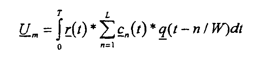
- the estimated value of the symbol U m is present.
Landscapes
- Engineering & Computer Science (AREA)
- Computer Networks & Wireless Communication (AREA)
- Signal Processing (AREA)
- Mobile Radio Communication Systems (AREA)
Abstract
Description
DECT [Digital Enhanced (früher: European) Cordless Telecommunication; vgl. Nachrichtentechnik Elektronik 42 (1992) Jan./Feb. Nr. 1, Berlin, DE; U. Pilger "Struktur des DECT-Standards", Seiten 23 bis 29 in Verbindung mit der ETSI-Publikation ETS 300175-1 ...9, Oktober 1992 und der DECT-Publikation des DECT-Forum, Februar 1997, Seiten 1 bis 16],
GSM [Groupe Speciale Mobile oder Global System for Mobile Communication; vgl. Informatik Spektrum 14 (1991) Juni, Nr. 3, Berlin, DE; A.Mann: "Der GSM-Standard - Grundlage für digitale europäische Mobilfunknetze", Seiten 137 bis 152 in Verbindung mit der Publikation telekom praxis 4/1993, P.Smolka "GSM-Funkschnittstelle - Elemente und Funktionen", Seiten 17 bis 24],
UMTS [Universal Mobile Telecommunication System; vgl. (1): Nachrichtentechnik Elektronik, Berlin 45, 1995, Heft 1, Seiten 10 bis 14 und Heft 2, Seiten 24 bis 27; P. Jung, B.Steiner: "Konzept eines CDMA-Mobilfunksystems mit gemeinsamer Detektion für die dritte Mobilfunkgeneration"; (2) : Nachrichtentechnik Elektronik, Berlin 41, 1991, Heft 6, Seiten 223 bis 227 und Seite 234; P.W. Baier, P.Jung, A.Klein: "CDMA - ein günstiges Vielfachzugriffsverfahren für frequenzselektive und zeitvariante Mobilfunkkanäle"; (3): IEICE Transactions on Fundamentals of Electonics, Communications and Computer Sciences, Vol. E79-A, No. 12, December 1996, Seiten 1930 bis 1937; P.W.Baier, P. Jung: "CDMA Myths and Realities Revisited"; (4) : IEEE Personal Communications, February 1995, Seiten 38 bis 47; A. Urie, M.Streeton, C.Mourot: "An Advanced TDMA Mobile Access System for UMTS"; (5) : telekom praxis, 5/1995, Seiten 9 bis 14; P.W.Baier: "Spread-Spectrum-Technik und CDMA - eine ursprünglich militärische Technik erobert den zivilen Bereich"; (6): IEEE Personal Communications, February 1995, Seiten 48 bis 53; P.G.Andermo, L.M.Ewerbring: "An CDMA-Based Radio Access Design for UMTS"; (7) : ITG Fachberichte 124 (1993), Berlin, Offenbach: VDE Verlag ISBN 3-8007-1965-7, Seiten 67 bis 75; Dr. T.Zimmermann, Siemens AG: "Anwendung von CDMA in der Mobilkommunikation"; (8): telcom report 16, (1993), Heft 1, Seiten 38 bis 41; Dr. T. Ketseoglou, Siemens AG und Dr. T.Zimmermann, Siemens AG: "Effizienter Teilnehmerzugriff für die 3. Generation der Mobilkommunikation - Vielfachzugriffsverfahren CDMA macht Luftschnittstelle flexibler"; (9): Funkschau 6/98: R. Sietmann "Ringen um die UMTS-Schnittstelle", Seiten 76 bis 81] WACS oder PACS, IS-54, IS-95, PHS, PDC etc. [vgl. IEEE Communications Magazine, January 1995, Seiten 50 bis 57; D.D. Falconer et al:"Time Division Multiple Access Methods for Wireless Personal Communications"]

- L +1 Addierer und
- 2 * L Multiplizierer (komplexe Multiplikation)
- 1 Addierer,
- 2 Multiplizierer und
- b+2*m zusätzliche Register,
Während des "Soft-Handover" senden die beteiligten Basisstation der Mobilstation dieselben Benutzerdaten zu. Zur Kontrolle der Sendeleistung der Mobilstation erhält diese zusätzlich eine Information, das sogenannte TPC-Bit (Transfer-Power-Control; vgl.: FIGUREN 1 und 2), ob die Sendeleistung runter oder rauf zu regeln ist. Deshalb müssen die unterschiedlichen, basisstationsabhängigen TPC-Bits dekodiert werden. Der abschließende bzw. letzte Teil der Verarbeitungspipeline akkumuliert dazu Symbole, die TPC-Bits darstellen, nach empfangener Basisstation getrennt auf.
Claims (4)
- Rake-Empfänger für Telekommunikationssysteme mit drahtloser Telekommunikation zwischen mobilen und/oder stationären Sende-/Empfangsgeräten mit
einer Pipeline-Architektur mit drei Pipeline-Stufen (PLS 1 ... PLS3), in denen die einzelnen Signalverarbeitungsschritten bzw. Rechenschritte nacheinander wie am Fließband abgearbeitet werden,
dadurch gekennzeichnet, daß
zwischen den Pipeline-Stufen (PLS1 ... PLS3) Register (RG1, RG2) zur Datenpufferung vorhanden sind,
ein Dual-Port-RAM (DPR), das in einem Zeitmultiplexverfahren nutzbar ist, in der ersten Pipeline-Stufe (PLS1) vorhanden ist,
wobei diese erste Pipeline-Stufe derart konfiguriert ist, daß
zum Auslesen empfangener Chips aus dem Dual-Port-RAM (DPR) eine Adresse durch Hinzuaddieren des Wertes eines freilaufenden Adresszählers zu Rake-Finger abhängigen Off-Sets berechnet wird,
mit Interpolationsmitteln (IPM), die eine Bestimmung konjugiert komplexer Koeffizienten mittels Interpolation zwischen zwei Kanalschätzungen gestatten, in einer zweiten Pipeline-Stufe (PLS2),
mit einem Akkumulator (AK) und einem Akkumulator Register (AKR) für ein Early/Late-Tracking der Rake-Finger in der dritten Pipeline-Stufe (PLS3). - Rake-Empfänger nach Anspruch 1, dadurch gekennzeichnet, daß
in der ersten Pipeline-Stufe (PLS1) eine erste Hardware-Schaltung (CCSHS) vorhanden ist, die das "Soft-Handover" unterstützt. - Rake-Empfänger nach einem der Ansprüche 1 oder 2, dadurch gekennzeichnet, daß
in der ersten Pipeline-Stufe (PLS1) eine zweite Hardware-Schaltung (CCSHS) vorhanden ist, die ein "Code-Combining" ermöglicht. - Rake-Empfänger nach einem der Ansprüche 1 bis 3, dadurch gekennzeichnet, daß
die Pipeline-Architektur durch das Einfügen von parallelen Verarbeitungszweigen flexibel an Wortbreiten und Taktraten anpassbar ist.
Applications Claiming Priority (3)
| Application Number | Priority Date | Filing Date | Title |
|---|---|---|---|
| DE19849556 | 1998-10-27 | ||
| DE19849556 | 1998-10-27 | ||
| PCT/DE1999/003365 WO2000025437A1 (de) | 1998-10-27 | 1999-10-27 | Rake-empfänger in mobilfunksystemen der dritten generation |
Publications (2)
| Publication Number | Publication Date |
|---|---|
| EP1125370A1 EP1125370A1 (de) | 2001-08-22 |
| EP1125370B1 true EP1125370B1 (de) | 2005-02-09 |
Family
ID=7885834
Family Applications (1)
| Application Number | Title | Priority Date | Filing Date |
|---|---|---|---|
| EP99957926A Expired - Lifetime EP1125370B1 (de) | 1998-10-27 | 1999-10-27 | Rake-empfänger in mobilfunksystemen der dritten generation |
Country Status (7)
| Country | Link |
|---|---|
| US (1) | US7031737B1 (de) |
| EP (1) | EP1125370B1 (de) |
| JP (1) | JP3610012B2 (de) |
| KR (1) | KR100430136B1 (de) |
| CN (1) | CN1146134C (de) |
| DE (1) | DE59911614D1 (de) |
| WO (1) | WO2000025437A1 (de) |
Families Citing this family (4)
| Publication number | Priority date | Publication date | Assignee | Title |
|---|---|---|---|---|
| US6771693B2 (en) * | 2001-12-27 | 2004-08-03 | Interdigital Technology Corporation | Enhanced rake structure |
| FR2845217B1 (fr) * | 2002-09-27 | 2004-12-17 | St Microelectronics Sa | Procede de traitement d'un signal incident au sein d'un recepteur "rake" a plusieurs doigts, et recepteur "rake" correspondant |
| DE10316800B4 (de) * | 2003-04-11 | 2005-07-07 | Infineon Technologies Ag | Verlustleistungsoptimierte Funkempfänger-Architektur |
| US7957453B2 (en) * | 2008-03-20 | 2011-06-07 | Raytheon Company | Method for operating a rake receiver |
Family Cites Families (7)
| Publication number | Priority date | Publication date | Assignee | Title |
|---|---|---|---|---|
| US5303261A (en) * | 1991-11-29 | 1994-04-12 | General Electric Company | High-throughput pipelined communication channel for interruptible data transmission |
| US5710768A (en) * | 1994-09-30 | 1998-01-20 | Qualcomm Incorporated | Method of searching for a bursty signal |
| US5654979A (en) | 1995-01-13 | 1997-08-05 | Qualcomm Incorporated | Cell site demodulation architecture for a spread spectrum multiple access communication systems |
| GB2300545B (en) * | 1995-05-03 | 1999-10-27 | Motorola Ltd | A method for processing signals |
| US6011787A (en) * | 1996-03-21 | 2000-01-04 | Ntt Mobile Communications Network Inc. | CDMA mobile communication scheme with effective use of sector configuration |
| US6064649A (en) * | 1997-01-31 | 2000-05-16 | Nec Usa, Inc. | Network interface card for wireless asynchronous transfer mode networks |
| US6470000B1 (en) * | 1998-10-14 | 2002-10-22 | Agere Systems Guardian Corp. | Shared correlator system and method for direct-sequence CDMA demodulation |
-
1999
- 1999-10-27 EP EP99957926A patent/EP1125370B1/de not_active Expired - Lifetime
- 1999-10-27 JP JP2000578919A patent/JP3610012B2/ja not_active Expired - Fee Related
- 1999-10-27 DE DE59911614T patent/DE59911614D1/de not_active Expired - Fee Related
- 1999-10-27 WO PCT/DE1999/003365 patent/WO2000025437A1/de not_active Ceased
- 1999-10-27 US US09/830,623 patent/US7031737B1/en not_active Expired - Fee Related
- 1999-10-27 CN CNB998127078A patent/CN1146134C/zh not_active Expired - Fee Related
- 1999-10-27 KR KR10-2001-7005311A patent/KR100430136B1/ko not_active Expired - Fee Related
Also Published As
| Publication number | Publication date |
|---|---|
| HK1041992A1 (en) | 2002-07-26 |
| WO2000025437A1 (de) | 2000-05-04 |
| JP2004500732A (ja) | 2004-01-08 |
| EP1125370A1 (de) | 2001-08-22 |
| DE59911614D1 (de) | 2005-03-17 |
| CN1324525A (zh) | 2001-11-28 |
| CN1146134C (zh) | 2004-04-14 |
| US7031737B1 (en) | 2006-04-18 |
| KR20010082263A (ko) | 2001-08-29 |
| JP3610012B2 (ja) | 2005-01-12 |
| KR100430136B1 (ko) | 2004-05-03 |
Similar Documents
| Publication | Publication Date | Title |
|---|---|---|
| EP1092296B1 (de) | Luftschnittstelle für telekommunikationssysteme mit drahtloser telekommunikation zwischen mobilen und/oder stationären sende-/empfangsgeräten | |
| DE3888793T2 (de) | TDMA-kohärenter Phasenquadraturenempfänger für Mehrwegkanäle mit Fading. | |
| DE3886712T2 (de) | TDMA-Funksystem mit einer BPSK-Synchronisierung für QPSK-Signale, die einer zufälligen Phasenveränderung und einem Mehrwegfading unterzogen werden. | |
| EP1000472B1 (de) | Verfahren und funkstation zur datenübertragung | |
| WO1999022454A2 (de) | Übertragungskanalschätzung in telekommunikationssystemen mit drahtloser telekommunikation | |
| WO1999044383A1 (de) | Telekommunikationssysteme mit drahtloser, auf code- und zeitmultiplex basierender telekommunikation zwischen mobilen und/oder stationären sende-/empfangsgeräten | |
| WO1999044313A1 (de) | Telekommunikationssysteme mit drahtloser, auf code- und zeitmultiplex basierender telekommunikation | |
| EP1000476B1 (de) | Verfahren und funkstation zur datenübertragung | |
| EP1058975B1 (de) | Tdd-telekommunikationssysteme mit drahtloser, auf code- und zeitmultiplex basierender telekommunikation | |
| WO1999022527A2 (de) | Verfahren und anordnung zur übertragung von daten über eine funkschnittstelle in einem funk-kommunikationssystem | |
| EP1133834B1 (de) | Verfahren zum steuern von speicherzugriffen bei "rake"-empfängern mit "early-late tracking" in telekommunikationssystemen | |
| EP1125370B1 (de) | Rake-empfänger in mobilfunksystemen der dritten generation | |
| WO1999044314A1 (de) | Luftschnittstelle für heim-telekommunikationssysteme mit drahtloser, auf code- und zeitmultiplex basierender telekommunikation | |
| DE19955357C2 (de) | Verfahren zur Signalübertragung in einem Funk-Kommunikationssystem und Teilnehmerstation | |
| DE19849552A1 (de) | Verfahren zum Regeln der Sendeleistung von mobilen Sende-/Empfangsgeräten in Telekommunikationssystemen mit drahtloser Telekommunikation zwischen mobilen und/oder stationären Sende-/Empfangsgeräten, insbesondere in Mobilfunksystemen der dritten Generation | |
| WO2000025530A2 (de) | Verfahren und anordnung zum schätzen von übertragungskanälen in mobilfunksystemen der dritten generation | |
| DE19849557A1 (de) | Verfahren zur hardwarebasierten Durchführung des Fingertracking eines Rake-Empfängers in Telekommunikationssystemen mit drahtloser Telekommunikation zwischen mobilen und/oder stationären Sende-/Empfangsgeräten, insbesondere in Mobilfunksystemen der dritten Generation | |
| DE19849544A1 (de) | Synchroner Rake-Empfänger für Tlekommunikationssysteme mit drahtloser Telekommunikation zwischen mobilen und/oder stationären Sende-/Empfangsgeräten, insbesondere in Mobilfunksystemen der dritten Generation | |
| DE19849559A1 (de) | Verfahren zum Herstellen der Zeitsynchronität zusätzlich zur Taktsynchronität auf der Empfängerseite in Telekommunikationssystemen mit drahtloser Telekommunikation zwischen mobilen und/oder stationären Sende-/Empfangsgeräten, insbesondere in Mobilfunksysteme der dritten Generation | |
| EP1072108A2 (de) | Telekommunikationssysteme mit drahtloser, auf code- und zeitmultiplex basierender telekommunikation | |
| DE19953486A1 (de) | Verfahren zur Synchronisation einer Signalübertragung in Aufwärtsrichtung in einem Funk-Kommunikationssystem | |
| EP1023790A1 (de) | Verfahren und funkstation zur datenübertragung | |
| DE19849533A1 (de) | Verfahren zum Steuern der Übertragung von Datenpaketen in Telekommunikationssystemen mit drahtloser Telekommunikation zwischen mobilen und/oder stationären Sende-/Empfangsgeräten, insbesondere in Mobilfunksystemen der dritten Generation | |
| KR100308151B1 (ko) | 샘플링된 상관 결과를 이용한 프레임 동기 확인 방법 |
Legal Events
| Date | Code | Title | Description |
|---|---|---|---|
| PUAI | Public reference made under article 153(3) epc to a published international application that has entered the european phase |
Free format text: ORIGINAL CODE: 0009012 |
|
| 17P | Request for examination filed |
Effective date: 20010223 |
|
| AK | Designated contracting states |
Kind code of ref document: A1 Designated state(s): AT BE CH CY DE DK ES FI FR GB GR IE IT LI LU MC NL PT SE |
|
| 17Q | First examination report despatched |
Effective date: 20040202 |
|
| RBV | Designated contracting states (corrected) |
Designated state(s): DE FR GB IT |
|
| GRAP | Despatch of communication of intention to grant a patent |
Free format text: ORIGINAL CODE: EPIDOSNIGR1 |
|
| GRAS | Grant fee paid |
Free format text: ORIGINAL CODE: EPIDOSNIGR3 |
|
| GRAA | (expected) grant |
Free format text: ORIGINAL CODE: 0009210 |
|
| AK | Designated contracting states |
Kind code of ref document: B1 Designated state(s): DE FR GB IT |
|
| REG | Reference to a national code |
Ref country code: GB Ref legal event code: FG4D Free format text: NOT ENGLISH |
|
| REG | Reference to a national code |
Ref country code: IE Ref legal event code: FG4D Free format text: GERMAN |
|
| REF | Corresponds to: |
Ref document number: 59911614 Country of ref document: DE Date of ref document: 20050317 Kind code of ref document: P |
|
| GBT | Gb: translation of ep patent filed (gb section 77(6)(a)/1977) |
Effective date: 20050320 |
|
| PLBE | No opposition filed within time limit |
Free format text: ORIGINAL CODE: 0009261 |
|
| STAA | Information on the status of an ep patent application or granted ep patent |
Free format text: STATUS: NO OPPOSITION FILED WITHIN TIME LIMIT |
|
| PGFP | Annual fee paid to national office [announced via postgrant information from national office to epo] |
Ref country code: DE Payment date: 20051219 Year of fee payment: 7 |
|
| ET | Fr: translation filed | ||
| 26N | No opposition filed |
Effective date: 20051110 |
|
| PGFP | Annual fee paid to national office [announced via postgrant information from national office to epo] |
Ref country code: GB Payment date: 20061012 Year of fee payment: 8 |
|
| PGFP | Annual fee paid to national office [announced via postgrant information from national office to epo] |
Ref country code: IT Payment date: 20061031 Year of fee payment: 8 |
|
| PG25 | Lapsed in a contracting state [announced via postgrant information from national office to epo] |
Ref country code: DE Free format text: LAPSE BECAUSE OF NON-PAYMENT OF DUE FEES Effective date: 20070501 |
|
| GBPC | Gb: european patent ceased through non-payment of renewal fee |
Effective date: 20071027 |
|
| REG | Reference to a national code |
Ref country code: FR Ref legal event code: ST Effective date: 20080630 |
|
| PGFP | Annual fee paid to national office [announced via postgrant information from national office to epo] |
Ref country code: FR Payment date: 20061018 Year of fee payment: 8 |
|
| PG25 | Lapsed in a contracting state [announced via postgrant information from national office to epo] |
Ref country code: GB Free format text: LAPSE BECAUSE OF NON-PAYMENT OF DUE FEES Effective date: 20071027 |
|
| PG25 | Lapsed in a contracting state [announced via postgrant information from national office to epo] |
Ref country code: FR Free format text: LAPSE BECAUSE OF NON-PAYMENT OF DUE FEES Effective date: 20071031 |
|
| PG25 | Lapsed in a contracting state [announced via postgrant information from national office to epo] |
Ref country code: IT Free format text: LAPSE BECAUSE OF NON-PAYMENT OF DUE FEES Effective date: 20071027 |