EP1125626B1 - Mélangeur statique - Google Patents
Mélangeur statique Download PDFInfo
- Publication number
- EP1125626B1 EP1125626B1 EP01810047A EP01810047A EP1125626B1 EP 1125626 B1 EP1125626 B1 EP 1125626B1 EP 01810047 A EP01810047 A EP 01810047A EP 01810047 A EP01810047 A EP 01810047A EP 1125626 B1 EP1125626 B1 EP 1125626B1
- Authority
- EP
- European Patent Office
- Prior art keywords
- chambers
- mixing
- mixer
- chamber
- tube
- Prior art date
- Legal status (The legal status is an assumption and is not a legal conclusion. Google has not performed a legal analysis and makes no representation as to the accuracy of the status listed.)
- Expired - Lifetime
Links
- 230000003068 static effect Effects 0.000 title claims description 19
- 238000002156 mixing Methods 0.000 claims description 43
- 230000004048 modification Effects 0.000 claims description 20
- 238000012986 modification Methods 0.000 claims description 20
- 230000009969 flowable effect Effects 0.000 claims description 6
- 239000000203 mixture Substances 0.000 claims description 6
- 229920001169 thermoplastic Polymers 0.000 claims description 3
- 239000004416 thermosoftening plastic Substances 0.000 claims description 3
- 238000002347 injection Methods 0.000 claims description 2
- 239000007924 injection Substances 0.000 claims description 2
- 239000012535 impurity Substances 0.000 description 5
- 238000000034 method Methods 0.000 description 4
- 238000004088 simulation Methods 0.000 description 3
- 230000007547 defect Effects 0.000 description 2
- 230000000694 effects Effects 0.000 description 2
- 230000000737 periodic effect Effects 0.000 description 2
- 230000003014 reinforcing effect Effects 0.000 description 2
- 239000000853 adhesive Substances 0.000 description 1
- 230000001070 adhesive effect Effects 0.000 description 1
- 238000010276 construction Methods 0.000 description 1
- 230000001419 dependent effect Effects 0.000 description 1
- 238000002474 experimental method Methods 0.000 description 1
- 239000006260 foam Substances 0.000 description 1
- 239000011346 highly viscous material Substances 0.000 description 1
- 238000001746 injection moulding Methods 0.000 description 1
- 238000009434 installation Methods 0.000 description 1
- 239000000463 material Substances 0.000 description 1
- 239000000565 sealant Substances 0.000 description 1
- 238000004904 shortening Methods 0.000 description 1
Images

Classifications
-
- B—PERFORMING OPERATIONS; TRANSPORTING
- B01—PHYSICAL OR CHEMICAL PROCESSES OR APPARATUS IN GENERAL
- B01F—MIXING, e.g. DISSOLVING, EMULSIFYING OR DISPERSING
- B01F23/00—Mixing according to the phases to be mixed, e.g. dispersing or emulsifying
- B01F23/40—Mixing liquids with liquids; Emulsifying
- B01F23/47—Mixing liquids with liquids; Emulsifying involving high-viscosity liquids, e.g. asphalt
-
- B—PERFORMING OPERATIONS; TRANSPORTING
- B01—PHYSICAL OR CHEMICAL PROCESSES OR APPARATUS IN GENERAL
- B01F—MIXING, e.g. DISSOLVING, EMULSIFYING OR DISPERSING
- B01F25/00—Flow mixers; Mixers for falling materials, e.g. solid particles
- B01F25/40—Static mixers
- B01F25/42—Static mixers in which the mixing is affected by moving the components jointly in changing directions, e.g. in tubes provided with baffles or obstructions
- B01F25/43—Mixing tubes, e.g. wherein the material is moved in a radial or partly reversed direction
- B01F25/432—Mixing tubes, e.g. wherein the material is moved in a radial or partly reversed direction with means for dividing the material flow into separate sub-flows and for repositioning and recombining these sub-flows; Cross-mixing, e.g. conducting the outer layer of the material nearer to the axis of the tube or vice-versa
- B01F25/4321—Mixing tubes, e.g. wherein the material is moved in a radial or partly reversed direction with means for dividing the material flow into separate sub-flows and for repositioning and recombining these sub-flows; Cross-mixing, e.g. conducting the outer layer of the material nearer to the axis of the tube or vice-versa the subflows consisting of at least two flat layers which are recombined, e.g. using means having restriction or expansion zones
-
- B—PERFORMING OPERATIONS; TRANSPORTING
- B01—PHYSICAL OR CHEMICAL PROCESSES OR APPARATUS IN GENERAL
- B01F—MIXING, e.g. DISSOLVING, EMULSIFYING OR DISPERSING
- B01F2101/00—Mixing characterised by the nature of the mixed materials or by the application field
- B01F2101/2305—Mixers of the two-component package type, i.e. where at least two components are separately stored, and are mixed in the moment of application
-
- B—PERFORMING OPERATIONS; TRANSPORTING
- B01—PHYSICAL OR CHEMICAL PROCESSES OR APPARATUS IN GENERAL
- B01F—MIXING, e.g. DISSOLVING, EMULSIFYING OR DISPERSING
- B01F33/00—Other mixers; Mixing plants; Combinations of mixers
- B01F33/50—Movable or transportable mixing devices or plants
- B01F33/501—Movable mixing devices, i.e. readily shifted or displaced from one place to another, e.g. portable during use
- B01F33/5011—Movable mixing devices, i.e. readily shifted or displaced from one place to another, e.g. portable during use portable during use, e.g. hand-held
Definitions
- the invention relates to a static mixer, a device with a such mixer and a use of the mixer.
- the mixing results of the mentioned mixers are in individual applications insufficient, especially in cases where components are mixed which have different values of their viscosity.
- One insufficient mixing results in the fact that at least one Streamline made of only one of the components to be mixed passes through the mixer structure with virtually no or one to undergoes slow mixing with adjacent flow filaments.
- One such flow thread is referred to herein as "mix resistant”.
- Mixed-resistant flow filaments are mainly found in static mixers before, whose mixer structure from a periodic sequence of similar consists of elementary mixing chambers. But even with non-periodic Mixer structures can be observed mixing resistant flow filaments.
- US-A-5 944 419 discloses current filament yarns in each mixer structure for better mixing of the components.
- the object of the invention is to provide a static mixer whose Mixed result is improved over the known mixers. These The object is achieved by the static mixer defined in claim 1.
- the static mixer comprises a plurality of mixing chambers, the one Forming mixer structure.
- the mixing chambers are in a tube along a Pipe axis behind and arranged side by side. They are for mixing of at least two flowable components usable.
- the Mixer structure represents a modification of a basic structure. In this Basic structure are the mixing chambers by radial, in the direction of Tube axis oriented walls and standing across the tube axis Walls demarcated against each other. Breakthroughs between adjacent Chambers in the radial walls form inputs and outputs for the mixing components.
- the modification consists of structural changes at individual points of the basic structure. It is designed so that in the Flow of the components to be mixed is a transversal Dislocation of mixed-resistant flow threads results, these Flow threads are resistant to mixing with respect to the basic structure.
- the impurities have in flow areas outside the mixed-resistant flow thread are, as a rule, a disadvantageous Effect on the mixing process. If this is the case, only just as many Defects are provided, as for a sufficient number of Dislocations of the mixed-resistant flow filaments is necessary.
- the defects can be formed so that they do not directly on the mix-resistant flow thread, but indirectly by putting in their direct sphere of influence cause deflections, which in turn then influence the mixed-resistant flow thread.
- An embodiment suitable impurities can be found empirically. One leads experiments with blending components that are differently colored, and compares the results for a basic structure with those of a modification of the Basic structure, whereby one can determine whether mix-resistant Streamline have actually been deployed.
- a device 100 is indicated by dash-dotted lines.
- the basic structure 1 consists of a variety of Mixing elements together, which are arranged in a tube 10 in a row are; or it consists of a bundle of four chambered strands, their mixing chambers 8 ("mixing chambers”) each between two closed ends 4a and 4b extend.
- Each of the mixing elements includes two axial sections, each of the sections at least one assigned to the section dividing divider 2 and 3 (radial walls) is.
- the dividers 2, 3 intersect and divide the pipe cross section in equal areas.
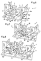
- the faces are open or through Deflecting discs 4 covered. Further details can be seen in the Drawings, in particular in FIG. 6, which show an unmodified basic structure 1 "with a mixing chamber 8 shown completely.
- the mixing chambers 8 of the basic structure 1 "are free of installation, the same size and offset from each other.
- Two inputs 6a, 6b and two Form outputs 7a, 7b arranged in an alternate sequence Connections to four adjacent chambers.
- Two side Reinforcing walls 5 extend over the entire length of the mixer. 1
- the device 100 comprises a two-chambered container 100a, namely a cartridge, with chambers 101 and 102. These are used for separate Inclusion of two flowable components A and B. Through outlets of the container 100a, A and B can by means of pistons 111 and 112 in the tube 10 are pressed (arrows A ', B'). After mixing A with B in the static mixer 1, which consists of the tube 10 and the mixer structure 1 ' composed, the mixture passes through a nozzle 120 from the device 100 off.
- the cartridge 100a may include more than two chambers.
- the Tube 10 may be a tubular part that can be placed on the cartridge 100a be educated.
- FIG. 2 A section along the line II - II is shown in Fig. 2.
- the mixer structure 1 ' is traversed by the two components A and B, the same values for the Have viscosity.
- Arrows in the mixing chamber 8 give the flow path (with the symbols 'circle with cross' and 'circle with point' arrows after below or above - refer to the image plane - mean).
- the Flow pattern is after results of a numerical simulation drawn. As you can see, the flow threads appear to be similarly thick Layers; this means a good mixing.
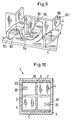
- Fig. 3 shows a corresponding representation as in Fig. 2, here for two Components A and B, their values for the viscosity by a factor of 100 are different.
- the less viscous component B forms much narrower Layers as this component flows faster.
- the flow threads unfold unevenly. Another unevenness is formed particularly strong over a cross-section perpendicular to the shown section is. These inequities have a bad one Mixing results.
- the modification 9 according to FIGS. 4 and 7 is inclined Web 91 formed in the mixing chamber 8 ', the pipe axis 11 or axis the mixer structure 1 'is inclined.
- the web 91 connects on a radial Wall 2 has an input 6b with an output 7a such that the Flow through the web 91 of the tube wall 10 in the direction of tube axis eleventh is deflected (arrow 91 '). Also the reversal is possible: one Flow deflection through the web 91 of the tube axis 11 in the direction Pipe wall 10.
- the modification 9 according to Figures 5 and 8 is by shortening the Lengths of three adjacent chambers 81, 82 and 83 at the same time Reduction in the number of inputs or outputs formed.
- the pair of the chambers 81 and 82 which lie one behind the other along the tube axis 11, arranged laterally from the third chamber 83.
- a modification 9 advantageously includes several impurities Modification elements 91 (first modification) and 81, 82, 83, 92 (second Modification), preferably regularly over the entire length of the static mixer 1 are positioned.
- Modification elements 91 and 81, 82, 83, 92 is particularly advantageous.
- FIG. 9 summarized shown: a) broken wall pieces 93, 94th and 95 effecting bypass flows (arrows 93 ', 94' and 95 '); and b) added webs 96, the passages between mixing chambers 8 narrow.
- FIG. 10 shows schematically by means of a cross section through the static mixer 1 mixed-resistant flow filaments 30 and 31.
- the Contours of these flow threads are less clear than shown; you are diffusely toothed and located in a wider environment 30 'and 31'.
- the mixer structures 11 'of the described embodiments are with Advantage each formed monolithic; In particular, they can be one Thermoplastic injection molded.
- the mixer structure 11 ' has a rectangular cross section and includes four juxtaposed Chamber strands. Each strand forms a series of 5 to 15 mixing chambers 8.
- Each chamber 8 of the basic structure has a length that is 1.5 to 2.5 times is longer than a chamber width, which width is greater than 1 mm and less than 10 mm, preferably at least 2mm and a maximum of 5 mm.
- the device 100 is suitable for mixing a high-viscosity Components A with at least one further component B, the one order may have a factor of 10 to 1000 smaller viscosity.
- the Mass flow of the further component can be many times, for example, by a factor of 10, less than the mass flow of be highly viscous components.
Landscapes
- Chemical & Material Sciences (AREA)
- Chemical Kinetics & Catalysis (AREA)
- Dispersion Chemistry (AREA)
- Engineering & Computer Science (AREA)
- Civil Engineering (AREA)
- Structural Engineering (AREA)
Claims (6)
- Mélangeur statique (1) pour le mélangeage d'au moins deux composants coulants (A, B), qui comporte un tube (10) et une structure de mélangeur (1') formée par une multitude de chambres de mélange (8), sachant que les chambres de mélange sont disposées le long d'un axe du tube (11) les unes derrière les autres de même que les unes à côté des autres, que chaque chambre de mélange comporte une structure de base avec des parois de séparation radiales (2, 3) qui sont orientées dans la direction de l'axe du tube, et avec des parois (4, 4a, 4b) se trouvant transversalement par rapport à l'axe du tube, des traversées dans les parois radiales longitudinales forment des entrées et des sorties pour les composants à mélanger, une majorité des chambres de mélange respectivement avec deux entrées (6a, 6b) et deux sorties (7a, 7b) forment des communications à quatre chambres voisines et certaines des chambres de mélange présentent respectivement une forme modifiée par rapport à la majorité des chambres de mélange, de telle sorte qu'une modification (9) se présente par rapport à une structure de base (1") formée seulement de chambres de mélange non modifiées, caractérisé en ce quede telle sorte que, par la modification (9), il s'ensuit dans le courant des composants à mélanger une dislocation transversale des filets d'écoulement résistant au mélangeage (30) qui sont résistants au mélangeage par rapport à la structure de base.la modification (9) est formée au moins en partie par des barrettes (91) inclinées par rapport à l'axe du tube (11), qui relient (91') respectivement dans une chambre de mélange (8') sur les parois radiales longitudinales (2, 3) une entrée (6b) à une sortie (7a) de telle sorte que l'écoulement est dévié par la barrette de la paroi du tube (10) en direction de l'axe du tube (11) ou inversement de l'axe du tube en direction de la paroi du tube,et/ou la modification (9) est formée au moins en partie par des raccourcissements des longueurs de trois chambres (81, 82, 83) voisines moyennant diminution simultanée du nombre des entrées et des sorties, sachant qu'une paire de chambres (81, 82) qui sont disposées l'une derrière l'autre le long de l'axe du tube (11) forment deux de ces chambres et que la troisième chambre (83), qui est disposée latéralement par rapport à la paire de chambres, réalise une communication (92') entre les deux chambres de la paire par deux traversées (7c, 92),
- Mélangeur statique selon la revendication 1, caractérisé en ce que la structure de mélangeur (1') est configurée de façon monolithique, en particulier moulée par injection en une matière thermoplastique.
- Mélangeur statique selon la revendication 1 ou 2, caractérisé en ce que la structure de mélangeur (1') a une section carrée ou rectangulaire, comporte quatre lignes de chambres disposées l'une à côté de l'autre, en ce que chaque ligne forme une série de 5 à 15 chambres (8) et en ce que chaque chambre de la structure de base (1'') présente une longueur qui est de 1,5 à 2,5 fois plus longue que la largeur de la chambre, sachant que cette largeur est plus grande que 1 mm et plus petite que 10 mm, qu'elle est de préférence au moins de 2 mm et au maximum de 5 mm.
- Dispositif (100) avec un récipient multichambre (100a) pour la réception séparée d'au moins deux composants coulants (A, B) qui peuvent être introduits à force dans une partie tubulaire (10) à travers des sorties du récipient, et avec une structure de mélangeur (1') disposée dans la partie tubulaire, qui forme avec la partie tubulaire un mélangeur statique (1) selon l'une des revendications 1 à 3.
- Dispositif selon la revendication 4, caractérisé en ce que les chambres (101, 102) du récipient (100a) sont cylindriques et en ce que des moyens en forme de pistons (111, 112) sont prévus, à l'aide desquels les composants coulants (A, B) peuvent être éjectés à force des chambres.
- Utilisation d'un mélangeur statique selon l'une quelconque des revendications 1 à 3, en particulier d'un dispositif (100) selon la revendication 7 ou 8, pour le mélangeage d'un composant hautement visqueux (A) avec au moins un autre composant (B) qui peut présenter une viscosité plus petite d'un facteur 10 à 1000, sachant que le débit massique de l'autre composant peut être plus petit d'un multiple que le débit massique du composant de haute viscosité.
Priority Applications (1)
| Application Number | Priority Date | Filing Date | Title |
|---|---|---|---|
| EP01810047A EP1125626B1 (fr) | 2000-02-17 | 2001-01-18 | Mélangeur statique |
Applications Claiming Priority (3)
| Application Number | Priority Date | Filing Date | Title |
|---|---|---|---|
| EP00810133 | 2000-02-17 | ||
| EP00810133 | 2000-02-17 | ||
| EP01810047A EP1125626B1 (fr) | 2000-02-17 | 2001-01-18 | Mélangeur statique |
Publications (2)
| Publication Number | Publication Date |
|---|---|
| EP1125626A1 EP1125626A1 (fr) | 2001-08-22 |
| EP1125626B1 true EP1125626B1 (fr) | 2005-11-02 |
Family
ID=26073780
Family Applications (1)
| Application Number | Title | Priority Date | Filing Date |
|---|---|---|---|
| EP01810047A Expired - Lifetime EP1125626B1 (fr) | 2000-02-17 | 2001-01-18 | Mélangeur statique |
Country Status (1)
| Country | Link |
|---|---|
| EP (1) | EP1125626B1 (fr) |
Cited By (4)
| Publication number | Priority date | Publication date | Assignee | Title |
|---|---|---|---|---|
| DE202011050465U1 (de) | 2011-06-16 | 2011-08-17 | Vosschemie Gmbh | Statischer Mischer zum Mischen von mindestens zwei fließfähigen Komponenten |
| DE102017117198A1 (de) | 2017-07-28 | 2019-01-31 | 3lmed GmbH | Mischer |
| WO2019020764A1 (fr) | 2017-07-28 | 2019-01-31 | Kettenbach Gmbh & Co. Kg | Mélangeur |
| US10898872B2 (en) | 2015-11-13 | 2021-01-26 | Re Mixers, Inc. | Static mixer |
Families Citing this family (19)
| Publication number | Priority date | Publication date | Assignee | Title |
|---|---|---|---|---|
| ATE242045T1 (de) * | 2002-03-22 | 2003-06-15 | Sulzer Chemtech Ag | Rohrmischer mit einem longitudinalen einbaukörper |
| PT1426099E (pt) * | 2002-12-06 | 2007-12-04 | Systems Ag | Misturador estático e método |
| ATE401123T1 (de) | 2004-12-17 | 2008-08-15 | Borealis Tech Oy | Verfahren zur polymerisation von olefinen in gegenwart eines olefin polymerisationskatalysators |
| EP1837070A1 (fr) | 2006-03-24 | 2007-09-26 | StaMixCo Technology AG | Mélangeur statique, et procédé de fabrication correspondant |
| DE102009054652A1 (de) * | 2009-12-15 | 2011-06-16 | Hilti Aktiengesellschaft | Statischer Mischer |
| ES2811725T3 (es) * | 2014-06-12 | 2021-03-15 | Huang Chia Hao | Mezclador |
| US10363526B2 (en) * | 2015-08-07 | 2019-07-30 | Nordson Corporation | Entry mixing elements and related static mixers and methods of mixing |
| US10245565B2 (en) | 2015-08-07 | 2019-04-02 | Nordson Corporation | Double wall flow shifter baffles and associated static mixer and methods of mixing |
| DE202015105397U1 (de) | 2015-10-13 | 2017-01-17 | Nikolaus Brugner | Statischer Mischer und Mischvorrichtung mit einem derartigen Mischer |
| EP3241611B1 (fr) | 2016-05-02 | 2020-03-04 | Borealis AG | Procédé d'alimentation d'un catalyseur de polymérisation |
| CH713229A1 (de) * | 2016-12-14 | 2018-06-15 | Streiff Felix | Mischelemente mit hoher Festigkeit und Mischwirkung. |
| DE202018106654U1 (de) | 2018-11-22 | 2019-02-06 | Sulzer Mixpac Ag | Statischer Mischer |
| EP4048435A4 (fr) | 2019-10-21 | 2023-11-29 | Re Mixers, Inc. | Mélangeur statique |
| CN111189759A (zh) * | 2020-01-14 | 2020-05-22 | 安徽奇书生物科技有限公司 | 一种灌流显微镜 |
| DE102021105414B9 (de) * | 2021-03-05 | 2022-11-17 | Kulzer Gmbh | Statischer Mischer für Abformmaterialien |
| EP4371657A1 (fr) | 2022-11-18 | 2024-05-22 | medmix Switzerland AG | Mélangeur statique |
| EP4371656A1 (fr) | 2022-11-18 | 2024-05-22 | medmix Switzerland AG | Mélangeur statique avec moyens de séparation |
| EP4494751A1 (fr) * | 2023-07-20 | 2025-01-22 | medmix Switzerland AG | Insert de mélangeur statique et mélangeur statique |
| CH720728A2 (de) | 2023-04-24 | 2024-10-31 | Streiff Felix | Statisches Mischelement mit einem Trennsteg und Umlenkflächen und statischer Mischer |
Family Cites Families (6)
| Publication number | Priority date | Publication date | Assignee | Title |
|---|---|---|---|---|
| US3239197A (en) * | 1960-05-31 | 1966-03-08 | Dow Chemical Co | Interfacial surface generator |
| FR1265659A (fr) * | 1960-08-19 | 1961-06-30 | Du Pont | égaliseur d'écoulement pour liquides |
| JPS5233822B2 (fr) * | 1972-03-18 | 1977-08-31 | ||
| DE2343352A1 (de) * | 1973-08-28 | 1975-03-13 | Worcester Valve Co Ltd | Vorrichtung zum mischen von fluden |
| DE3420290C1 (de) * | 1984-05-30 | 1986-01-02 | Ritter-Plastic GmbH, 8931 Untermeitingen | Statisches Mischteil |
| EP0749776B1 (fr) * | 1995-06-21 | 2001-01-24 | Sulzer Chemtech AG | Mélangeur avec corps en forme de tube |
-
2001
- 2001-01-18 EP EP01810047A patent/EP1125626B1/fr not_active Expired - Lifetime
Cited By (6)
| Publication number | Priority date | Publication date | Assignee | Title |
|---|---|---|---|---|
| DE202011050465U1 (de) | 2011-06-16 | 2011-08-17 | Vosschemie Gmbh | Statischer Mischer zum Mischen von mindestens zwei fließfähigen Komponenten |
| WO2012172078A1 (fr) | 2011-06-16 | 2012-12-20 | Vosschemie Gmbh | Mélangeur statique pour mélanger au moins deux composants fluides |
| US10898872B2 (en) | 2015-11-13 | 2021-01-26 | Re Mixers, Inc. | Static mixer |
| US11786876B2 (en) | 2015-11-13 | 2023-10-17 | Re Mixers, Inc. | Static mixer |
| DE102017117198A1 (de) | 2017-07-28 | 2019-01-31 | 3lmed GmbH | Mischer |
| WO2019020764A1 (fr) | 2017-07-28 | 2019-01-31 | Kettenbach Gmbh & Co. Kg | Mélangeur |
Also Published As
| Publication number | Publication date |
|---|---|
| EP1125626A1 (fr) | 2001-08-22 |
Similar Documents
| Publication | Publication Date | Title |
|---|---|---|
| EP1125626B1 (fr) | Mélangeur statique | |
| EP0815929B1 (fr) | Mélangeur statique | |
| EP1312409B1 (fr) | Mélangeur de tube avec un élément longitudinal | |
| DE4134026C2 (de) | Gleichdrallschneckenkneter | |
| EP1426099B1 (fr) | Mélangeur statique et procédé | |
| EP2548634B1 (fr) | Elément de mélange pour mélangeur statique | |
| DE2708200C2 (de) | Statische Mischeinrichtung für eine Kunststoffmaschine, insbesondere Spritzgießmaschine oder Extruder | |
| EP1458467A1 (fr) | Dispositif pour melanger deux matieres pateuses, notamment pour melanger une matiere pour empreinte dentaire avec une matiere catalytique | |
| EP2614883B1 (fr) | élément de mélange et mélangeur statique | |
| DE2913940C2 (de) | Statischer Mischer | |
| DE2100192B2 (de) | Strangpresskopf zum herstellen eines hohlstranges | |
| DE2905866C2 (de) | Vorrichtung zum Strangpressen eines Kunststoffes | |
| EP2001580B1 (fr) | Mélangeur statique et son procédé de fabrication | |
| CH643467A5 (de) | Mischer, enthaltend mindestens einen einsatz, welcher mindestens zwei sich kreuzende scharen von kanaelen enthaelt. | |
| EP1588757B1 (fr) | Mélangeur statique pour la production de mélanges durcissables de composants liquides, et son utilisation | |
| EP1149626B1 (fr) | Elément de mélange statique et mélangeur statique ainsi que leur application | |
| AT408860B (de) | Verfahren zum durchmischen eines schmelzenstromes aus kunststoff | |
| WO2019020764A1 (fr) | Mélangeur | |
| DE4202591C2 (de) | Vorrichtung zum Vormischen von wenigstens zwei pastösen Massen | |
| EP4143001B1 (fr) | Unité de plastification | |
| DE102017117198A1 (de) | Mischer | |
| DE2802125A1 (de) | Schneckenmaschine zum bearbeiten von festen, fluessigen und zaehviskosen materialien | |
| DE4138351A1 (de) | Verfahren und vorrichtung zum vormischen zweier pastoeser massen | |
| DE202021105311U1 (de) | Einstückiger statischer Mischer | |
| EP1775098A1 (fr) | Dispositif de convoyage et d'extrusion |
Legal Events
| Date | Code | Title | Description |
|---|---|---|---|
| PUAI | Public reference made under article 153(3) epc to a published international application that has entered the european phase |
Free format text: ORIGINAL CODE: 0009012 |
|
| AK | Designated contracting states |
Kind code of ref document: A1 Designated state(s): AT BE CH CY DE DK ES FI FR GB GR IE IT LI LU MC NL PT SE TR |
|
| AX | Request for extension of the european patent |
Free format text: AL;LT;LV;MK;RO;SI |
|
| 17P | Request for examination filed |
Effective date: 20011227 |
|
| AKX | Designation fees paid |
Free format text: AT BE CH CY DE DK ES FI FR GB GR IE IT LI LU MC NL PT SE TR |
|
| 17Q | First examination report despatched |
Effective date: 20040729 |
|
| GRAP | Despatch of communication of intention to grant a patent |
Free format text: ORIGINAL CODE: EPIDOSNIGR1 |
|
| GRAS | Grant fee paid |
Free format text: ORIGINAL CODE: EPIDOSNIGR3 |
|
| GRAA | (expected) grant |
Free format text: ORIGINAL CODE: 0009210 |
|
| AK | Designated contracting states |
Kind code of ref document: B1 Designated state(s): AT BE CH CY DE DK ES FI FR GB GR IE IT LI LU MC NL PT SE TR |
|
| PG25 | Lapsed in a contracting state [announced via postgrant information from national office to epo] |
Ref country code: IE Free format text: LAPSE BECAUSE OF FAILURE TO SUBMIT A TRANSLATION OF THE DESCRIPTION OR TO PAY THE FEE WITHIN THE PRESCRIBED TIME-LIMIT Effective date: 20051102 Ref country code: FI Free format text: LAPSE BECAUSE OF FAILURE TO SUBMIT A TRANSLATION OF THE DESCRIPTION OR TO PAY THE FEE WITHIN THE PRESCRIBED TIME-LIMIT Effective date: 20051102 Ref country code: NL Free format text: LAPSE BECAUSE OF FAILURE TO SUBMIT A TRANSLATION OF THE DESCRIPTION OR TO PAY THE FEE WITHIN THE PRESCRIBED TIME-LIMIT Effective date: 20051102 |
|
| REG | Reference to a national code |
Ref country code: GB Ref legal event code: FG4D Free format text: NOT ENGLISH |
|
| REG | Reference to a national code |
Ref country code: CH Ref legal event code: EP |
|
| REG | Reference to a national code |
Ref country code: CH Ref legal event code: NV Representative=s name: SULZER MANAGEMENT AG PATENTABTEILUNG/0067 |
|
| REF | Corresponds to: |
Ref document number: 50107866 Country of ref document: DE Date of ref document: 20051208 Kind code of ref document: P |
|
| PG25 | Lapsed in a contracting state [announced via postgrant information from national office to epo] |
Ref country code: AT Free format text: LAPSE BECAUSE OF NON-PAYMENT OF DUE FEES Effective date: 20060118 |
|
| PG25 | Lapsed in a contracting state [announced via postgrant information from national office to epo] |
Ref country code: LU Free format text: LAPSE BECAUSE OF NON-PAYMENT OF DUE FEES Effective date: 20060131 Ref country code: BE Free format text: LAPSE BECAUSE OF NON-PAYMENT OF DUE FEES Effective date: 20060131 Ref country code: MC Free format text: LAPSE BECAUSE OF NON-PAYMENT OF DUE FEES Effective date: 20060131 |
|
| PG25 | Lapsed in a contracting state [announced via postgrant information from national office to epo] |
Ref country code: SE Free format text: LAPSE BECAUSE OF FAILURE TO SUBMIT A TRANSLATION OF THE DESCRIPTION OR TO PAY THE FEE WITHIN THE PRESCRIBED TIME-LIMIT Effective date: 20060202 Ref country code: GR Free format text: LAPSE BECAUSE OF FAILURE TO SUBMIT A TRANSLATION OF THE DESCRIPTION OR TO PAY THE FEE WITHIN THE PRESCRIBED TIME-LIMIT Effective date: 20060202 Ref country code: DK Free format text: LAPSE BECAUSE OF FAILURE TO SUBMIT A TRANSLATION OF THE DESCRIPTION OR TO PAY THE FEE WITHIN THE PRESCRIBED TIME-LIMIT Effective date: 20060202 |
|
| PG25 | Lapsed in a contracting state [announced via postgrant information from national office to epo] |
Ref country code: ES Free format text: LAPSE BECAUSE OF FAILURE TO SUBMIT A TRANSLATION OF THE DESCRIPTION OR TO PAY THE FEE WITHIN THE PRESCRIBED TIME-LIMIT Effective date: 20060213 |
|
| PG25 | Lapsed in a contracting state [announced via postgrant information from national office to epo] |
Ref country code: PT Free format text: LAPSE BECAUSE OF FAILURE TO SUBMIT A TRANSLATION OF THE DESCRIPTION OR TO PAY THE FEE WITHIN THE PRESCRIBED TIME-LIMIT Effective date: 20060403 |
|
| NLV1 | Nl: lapsed or annulled due to failure to fulfill the requirements of art. 29p and 29m of the patents act | ||
| GBT | Gb: translation of ep patent filed (gb section 77(6)(a)/1977) |
Effective date: 20060413 |
|
| ET | Fr: translation filed | ||
| REG | Reference to a national code |
Ref country code: IE Ref legal event code: FD4D |
|
| PLBE | No opposition filed within time limit |
Free format text: ORIGINAL CODE: 0009261 |
|
| STAA | Information on the status of an ep patent application or granted ep patent |
Free format text: STATUS: NO OPPOSITION FILED WITHIN TIME LIMIT |
|
| 26N | No opposition filed |
Effective date: 20060803 |
|
| BERE | Be: lapsed |
Owner name: SULZER CHEMTECH A.G. Effective date: 20060131 |
|
| PG25 | Lapsed in a contracting state [announced via postgrant information from national office to epo] |
Ref country code: TR Free format text: LAPSE BECAUSE OF FAILURE TO SUBMIT A TRANSLATION OF THE DESCRIPTION OR TO PAY THE FEE WITHIN THE PRESCRIBED TIME-LIMIT Effective date: 20051102 |
|
| PG25 | Lapsed in a contracting state [announced via postgrant information from national office to epo] |
Ref country code: CY Free format text: LAPSE BECAUSE OF FAILURE TO SUBMIT A TRANSLATION OF THE DESCRIPTION OR TO PAY THE FEE WITHIN THE PRESCRIBED TIME-LIMIT Effective date: 20051102 |
|
| REG | Reference to a national code |
Ref country code: CH Ref legal event code: NV Representative=s name: DR. GRAF AND PARTNER AG INTELLECTUAL PROPERTY, CH Ref country code: CH Ref legal event code: PCOW Free format text: NEW ADDRESS: SULZERALLEE 48, 8404 WINTERTHUR (CH) |
|
| REG | Reference to a national code |
Ref country code: FR Ref legal event code: PLFP Year of fee payment: 16 |
|
| REG | Reference to a national code |
Ref country code: FR Ref legal event code: PLFP Year of fee payment: 17 |
|
| REG | Reference to a national code |
Ref country code: FR Ref legal event code: PLFP Year of fee payment: 18 |
|
| PGFP | Annual fee paid to national office [announced via postgrant information from national office to epo] |
Ref country code: IT Payment date: 20200131 Year of fee payment: 20 Ref country code: DE Payment date: 20200121 Year of fee payment: 20 Ref country code: GB Payment date: 20200123 Year of fee payment: 20 |
|
| PGFP | Annual fee paid to national office [announced via postgrant information from national office to epo] |
Ref country code: CH Payment date: 20200121 Year of fee payment: 20 |
|
| PGFP | Annual fee paid to national office [announced via postgrant information from national office to epo] |
Ref country code: FR Payment date: 20200121 Year of fee payment: 20 |
|
| REG | Reference to a national code |
Ref country code: DE Ref legal event code: R071 Ref document number: 50107866 Country of ref document: DE |
|
| REG | Reference to a national code |
Ref country code: CH Ref legal event code: PL |
|
| REG | Reference to a national code |
Ref country code: GB Ref legal event code: PE20 Expiry date: 20210117 |
|
| PG25 | Lapsed in a contracting state [announced via postgrant information from national office to epo] |
Ref country code: GB Free format text: LAPSE BECAUSE OF EXPIRATION OF PROTECTION Effective date: 20210117 |