EP1125663B1 - Outil de forage pour la pierre - Google Patents
Outil de forage pour la pierre Download PDFInfo
- Publication number
- EP1125663B1 EP1125663B1 EP01810116A EP01810116A EP1125663B1 EP 1125663 B1 EP1125663 B1 EP 1125663B1 EP 01810116 A EP01810116 A EP 01810116A EP 01810116 A EP01810116 A EP 01810116A EP 1125663 B1 EP1125663 B1 EP 1125663B1
- Authority
- EP
- European Patent Office
- Prior art keywords
- cutting edges
- drilling tool
- tool according
- main cutting
- concave
- Prior art date
- Legal status (The legal status is an assumption and is not a legal conclusion. Google has not performed a legal analysis and makes no representation as to the accuracy of the status listed.)
- Expired - Lifetime
Links
Images

Classifications
-
- B—PERFORMING OPERATIONS; TRANSPORTING
- B23—MACHINE TOOLS; METAL-WORKING NOT OTHERWISE PROVIDED FOR
- B23B—TURNING; BORING
- B23B51/00—Tools for drilling machines
- B23B51/02—Twist drills
-
- B—PERFORMING OPERATIONS; TRANSPORTING
- B23—MACHINE TOOLS; METAL-WORKING NOT OTHERWISE PROVIDED FOR
- B23B—TURNING; BORING
- B23B2222/00—Materials of tools or workpieces composed of metals, alloys or metal matrices
- B23B2222/28—Details of hard metal, i.e. cemented carbide
-
- B—PERFORMING OPERATIONS; TRANSPORTING
- B23—MACHINE TOOLS; METAL-WORKING NOT OTHERWISE PROVIDED FOR
- B23B—TURNING; BORING
- B23B2226/00—Materials of tools or workpieces not comprising a metal
- B23B2226/75—Stone, rock or concrete
-
- B—PERFORMING OPERATIONS; TRANSPORTING
- B23—MACHINE TOOLS; METAL-WORKING NOT OTHERWISE PROVIDED FOR
- B23B—TURNING; BORING
- B23B2251/00—Details of tools for drilling machines
- B23B2251/20—Number of cutting edges
- B23B2251/204—Four cutting edges
Definitions
- the invention refers to a drilling tool with a solid carbide head for rock or concrete, which generates a abrasive material removal clamped in a driving hand tool by rotating and hitting oscillating movements.
- Drilling tools for rock or concrete have due to the high hardness required for abrasive material removal with low wear in the tool head parts made of hard metal, which are firmly connected to the rest of the drilling tool.
- carbide plates are soldered in the tool head, eg. After the DE2008825 or the DE 298 193 88 U , The relatively low bending stiffness of the hard metal plates favors a breaking out of these from the rest of the drilling tool, especially in Arm michsseisentreffern.
- Solid carbide heads in compact ie substantially in convex polygonal shape with similar side lengths, have a high internal stiffness.
- To prevent entanglement in the reinforcing iron usually additionally arranged between the main cutting exclusively on the radial edge axially recessed secondary cutting present, which counteract by their penetration resistance and inertia too deep penetration of the main cutting into the reinforcing iron by temporarily lifting the drill from the reinforcing iron.
- the required volume of the solid carbide head in a compact form in terms of manufacturing and cost aspects disadvantageous.
- a slightly axially concave ie a plane extending through the radially outer edges perpendicular to the axis of rotation does not undercut, form of an obtuse angle symmetrical to the axis of rotation forming and axially recessed radially extending minor cutting edge is already known.
- This slightly axially concave shape of the secondary cutting edge in cooperation with the borehole cut by a non-concave main cutting edge, serves as an axial clearance for the removal of the drilling dust from the tip of the tool head and prevents a performance-reducing drilling dust compaction in front of the tip. adversely in such a slightly axially concave shape is the appropriate combination with a non-concave shape of the main cutting edge, which makes a pinpoint drilling difficult.
- the "X-shaped solid carbide head has a two-fold rotationally symmetrical substantially crosswise mirror-symmetrical prismatic shape.”
- the base is provided with a deep, concave, obtuse-angled notch extending parallel to the blades over the longer side of the base In the direction of rotation, the additional cutting edge of the main cutting edge travels, ie forms an acute angle with it, so that the large recess is arranged in front of the main cutting edge.
- a small, likewise concave recess of the respective shorter side of the base area is limited to the radial edge area and serves to reduce the removal of the abraded material in front of the secondary cutting edge.
- a rotation angle to be bridged by the secondary inertia is required for reducing the entanglement caused by the minor cutting edge, which is hardly feasible with larger diameter drilling tools operated at a lower rotational speed, and thus none adequate protection against breaks in armor hits.
- the invention is restricted to boring tools with a solid carbide head with an X-shaped arrangement of the four cutting edges, the main and minor cutting edges each extending diametrically to the axis of rotation and not being arranged at right angles to one another
- the boring tools according to the invention have a diameter of 12 to 40 It is essential that the secondary cutting edges designed to reduce the stress on the main cutting edges in the case of reinforcing impacts are arranged in advance. The angle formed between them in the plane perpendicular to the axis of rotation is in the range between 40 and 90 ° Rotation angle can be bridged by the inertia.
- each between two adjacent cutting each piecewise parallel to these extending radially concave recess on the circumference of the cross-sectional area and their prismatic axial extent on the solid carbide head allows sufficient clearing of the abraded material in the adjoining the tool head as solid carbide head helix, in particular before the main cutting edge.
- This part of the side surfaces advantageously has a phase to the end face for refraction of the edge.
- the shape of the main cutting edges which open in the tip in a transverse cutting, slightly axially concave, resulting in a relatively acute angle with respect to the tip portion for pinpoint drilling through the transverse cutting edge and with respect to the radial outer portion a relatively duller angle of the main cutting to the axis of rotation forms, which introduces the energy of the axial blows of the drilling tool almost completely axially and thus low-loss in the ablated material in the bottom of the hole.
- the shape of the minor cutting edges is highly axially concave, i. a cutting through the radially outer regions of the minor cutting edges perpendicular to the axis of rotation cutting formed.
- the transitional area in the sector between adjacent cutting edges is advantageously designed to be circumferentially axially concave in order to obtain a large recess for the removal of the drilling dust and to achieve a high internal rigidity of the solid carbide head.
- the axial distance of the minor cutting edges is chosen such that the highest point of the axial envelope of the minor cutting edges does not project beyond the axial envelope of the main cutting edges.
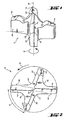
- a solid carbide head 1 for a drilling tool advantageously 12 to 40 mm bore diameter has an "X-shaped arrangement of four cutting edges 2, 3, the main cutting edges 2 and the minor cutting edges 3 each extending diametrically to the axis of rotation A and not being arranged at right angles to each other at an acute angle to the main cutting edges 2 associated minor cutting edges 3 are arranged in advance with respect to the direction of rotation ⁇ the main cutting edges 2.
- Fig. 2 is formed between the main cutting edges 2 and the minor cutting edges 3 in the plane perpendicular to the axis of rotation formed angle ⁇ in the range between 40 and 90 °, the minor cutting edges 3 are arranged with respect to the direction of rotation ⁇ the main cutting edge 2 in advance.
- the secondary cutting edges 3 have a radial shelter.
- In each case between two adjacent cutting edges 2; 3 is a piecewise parallel to this extending radially concave recess 4; 5 on the circumference of the cross-sectional area and their prismatic axial extent over the solid carbide head 1 present.
- the part of the along the axis of rotation of the recesses 5 extending side surfaces 6, advantageously in front of the minor cutting edge 3, erine an additional attachment of the solid carbide head in groove-shaped taps on the rest of the drilling tool.
- this part of the side surfaces 6 a phase 7 to the end face 8 for refraction of the edge.
- the shape of the main cutting edges 2, which open in the tip in a transverse cutting edge 9, are slightly axially concave.
- the axial distance of the minor cutting edges 3 is selected such that the highest point of the axial envelope of the minor cutting edges 3 does not project beyond the axial envelope of the main cutting edges 2.
- a plane 10 extending through the radially outer regions of the minor cutting edge 3 perpendicular to the axis of rotation is cut.
- the transition surface 12 in the sector between adjacent blades 2; 3 is formed circumferentially axially concave.
Landscapes
- Engineering & Computer Science (AREA)
- Mechanical Engineering (AREA)
- Drilling Tools (AREA)
- Processing Of Stones Or Stones Resemblance Materials (AREA)
- Earth Drilling (AREA)
Claims (10)
- Foret comprenant une tête pleine en métal dur (1), laquelle comporte des taillants principaux 12) et des taillants secondaires (3), les taillants principaux (2) et les taillants secondaires (3) prévus chacun en double et opposés diamétralement l'un à l'autre n'étant pas disposés à angle droit les uns par rapport aux autres, caractérisé en ce que les taillants secondaires (3), desquels forment un angle aigu α avec les taillants principaux (2), sont situés devant les taillants principaux associés (2) par rapport au sens de rotation ω.
- Foret selon la revendication 1, caractérisé en ce que l'angle α formé entre les taillants principaux (2) et les taillants secondaires (3) dans le plan perpendiculaire à l'axe de rotation A est compris entre 40 et 90°.
- Foret selon une des revendications précédentes, caractérisé en ce qu'un évidement concave radial (4 ; 5) s'étendant en partie entre deux taillants voisins (2 ; 3) parallèlement à ceux-ci est ménagé sur le pourtour de la surface transversale ainsi que de son extension axiale prismatique sur la tête pleine en métal dur (1).
- Foret selon la revendication 3, caractérisé en ce que la partie des surfaces latérales (6) de l'évidement (5) qui s'étendent suivant l'axe de rotation A et se trouvent devant le taillant secondaire (3) par rapport au sens de rotation ω présente un biseau (7) vers une face frontale (8).
- Foret selon une des revendications précédentes, caractérisé en ce que, au niveau de la pointe, les taillants principaux (2) se terminent par un taillant transversal (9).
- Foret selon une des revendications précédentes, caractérisé en ce que la forme des taillants principaux (2) est légèrement concave axialement.
- Foret selon une des revendications précédentes, caractérisé en ce que la forme des taillants secondaires (3) est fortement concave axialement.
- Foret selon une des revendications précédentes, caractérisé en ce que l'écartement axial des taillants secondaires (3) est choisi de façon que le point le plus haut de l'enveloppante axiale des taillants secondaires (3) ne dépasse pas l'enveloppante axiale des taillants principaux (2).
- Foret selon une des revendications précédentes, caractérisé en ce que, par rapport à l'enveloppante des taillants principaux (2), les taillants secondaires (3) présentent un retrait radial.
- Foret selon une des revendications précédentes, caractérisé en ce que la surface de transition (12) dans le secteur situé entre des taillants voisins (2; 3) est de forme axialement concave en périphérie.
Applications Claiming Priority (2)
| Application Number | Priority Date | Filing Date | Title |
|---|---|---|---|
| DE10006932A DE10006932A1 (de) | 2000-02-16 | 2000-02-16 | Bohrwerkzeug für Gestein |
| DE10006932 | 2000-02-16 |
Publications (3)
| Publication Number | Publication Date |
|---|---|
| EP1125663A2 EP1125663A2 (fr) | 2001-08-22 |
| EP1125663A3 EP1125663A3 (fr) | 2002-06-05 |
| EP1125663B1 true EP1125663B1 (fr) | 2009-06-10 |
Family
ID=7631111
Family Applications (1)
| Application Number | Title | Priority Date | Filing Date |
|---|---|---|---|
| EP01810116A Expired - Lifetime EP1125663B1 (fr) | 2000-02-16 | 2001-02-06 | Outil de forage pour la pierre |
Country Status (5)
| Country | Link |
|---|---|
| US (1) | US20010013430A1 (fr) |
| EP (1) | EP1125663B1 (fr) |
| JP (1) | JP2001252807A (fr) |
| DE (2) | DE10006932A1 (fr) |
| ZA (1) | ZA200101301B (fr) |
Cited By (2)
| Publication number | Priority date | Publication date | Assignee | Title |
|---|---|---|---|---|
| US7861807B2 (en) | 2008-12-03 | 2011-01-04 | Black & Decker Inc. | Drill bit including one piece cutting head |
| US12070807B2 (en) | 2021-03-18 | 2024-08-27 | Black & Decker Inc. | One-piece cutting head for a drill bit |
Families Citing this family (29)
| Publication number | Priority date | Publication date | Assignee | Title |
|---|---|---|---|---|
| DE10009732A1 (de) * | 2000-03-02 | 2001-09-06 | Hawera Probst Gmbh | Gesteinsbohrer |
| DE10117262A1 (de) * | 2001-01-17 | 2002-07-18 | Hilti Ag | Gesteinsbohrer |
| US6860344B2 (en) * | 2001-06-25 | 2005-03-01 | Kennametal Inc. | Monolithic roof cutting bit insert |
| JP4189380B2 (ja) * | 2002-06-06 | 2008-12-03 | 株式会社ミヤナガ | ドリルビット |
| RU2283224C2 (ru) * | 2002-06-06 | 2006-09-10 | Кабусики Кайся Миянага | Сверло |
| DE102004022747A1 (de) * | 2004-05-07 | 2005-11-24 | Fischerwerke Artur Fischer Gmbh & Co. Kg | Spanwerkzeug mit geometrisch bestimmten Schneiden für Drehantrieb |
| DE102004028098A1 (de) * | 2004-06-09 | 2005-12-29 | Hilti Ag | Bohrer |
| DE102004047469A1 (de) * | 2004-09-30 | 2006-04-06 | Robert Bosch Gmbh | Bohrwerkzeug mit einem als Platte oder Kopf ausgebildeten Schneidelement |
| CN101096056B (zh) * | 2006-03-02 | 2013-06-19 | 密尔沃基电动工具公司 | 切削刀具 |
| US8328477B2 (en) | 2006-03-02 | 2012-12-11 | Milwaukee Electric Tool Corporation | Cutting tool |
| DE102006000201A1 (de) * | 2006-04-27 | 2007-10-31 | Hilti Ag | Hartstoffeinsatz |
| DE102006020538A1 (de) | 2006-05-03 | 2007-11-15 | Irwin Industrial Tools Gmbh | Bohrkopf für Bohrwerkzeug und Bohrwerkzeug |
| DE102006000221A1 (de) * | 2006-05-10 | 2007-11-15 | Hilti Ag | Hartstoffbohrkopf |
| DE102006035443B3 (de) * | 2006-11-15 | 2008-02-21 | Hilti Ag | Bohrwerkzeug mit Hartstoffkopf |
| DE102006035453A1 (de) | 2006-11-17 | 2008-05-21 | Hilti Ag | Bohrwerkzeug mit Hartstoffkopf |
| DE202007002120U1 (de) * | 2007-02-08 | 2008-06-19 | Illinois Tool Works Inc., Glenview | Gesteinsbohrer |
| USD605672S1 (en) * | 2007-03-01 | 2009-12-08 | Milwaukee Electric Tool Corporation | Cutting blade |
| USD575808S1 (en) | 2007-03-02 | 2008-08-26 | Milwaukee Electric Tool Corporation | Cutting tool |
| DE202007010827U1 (de) * | 2007-08-03 | 2008-12-18 | Drebo Werkzeugfabrik Gmbh | Bohrer mit einem Hartmetalleinsatz an dem Bohrerkopf |
| DE102007000534A1 (de) * | 2007-10-19 | 2009-04-23 | Hilti Aktiengesellschaft | Schlagbohrwerkzeug |
| DE102008048599A1 (de) | 2008-09-23 | 2010-03-25 | Illinois Tool Works Inc., Glenview | Gesteinsbohrer |
| DE102008062298B4 (de) | 2008-12-15 | 2025-05-15 | Drebo Werkzeugfabrik Gmbh | Bohrkörper |
| FR2943565B1 (fr) * | 2009-03-27 | 2012-12-28 | Diager | Plaquette de coupe pour outil rotatif de percage |
| EP2669033B1 (fr) | 2012-05-29 | 2015-11-04 | Black & Decker Inc. | Tête de coupe pour un foret. |
| WO2014121117A1 (fr) | 2013-02-01 | 2014-08-07 | Milwaukee Electric Tool Corporation | Mèche de tarière ayant un taillant remplaçable |
| FR3004747B1 (fr) * | 2013-04-19 | 2017-11-03 | Diager | Plaquette de coupe |
| JP6253533B2 (ja) * | 2014-07-01 | 2017-12-27 | 株式会社神戸製鋼所 | 切削工具の製造方法 |
| DE102023206478A1 (de) * | 2023-07-07 | 2025-01-09 | Robert Bosch Gesellschaft mit beschränkter Haftung | Bohrwerkzeug mit einem Bohrkopf, der eine zentrale Pyramide aufweist |
| DE102023206483A1 (de) * | 2023-07-07 | 2025-01-09 | Robert Bosch Gesellschaft mit beschränkter Haftung | Bohrwerkzeug mit einem Bohrkopf |
Family Cites Families (4)
| Publication number | Priority date | Publication date | Assignee | Title |
|---|---|---|---|---|
| DE19545648A1 (de) * | 1995-12-07 | 1997-06-12 | Hilti Ag | Drehschlag-Wendelbohrer |
| DE19709771B4 (de) * | 1997-03-10 | 2008-03-20 | Drebo Werkzeugfabrik Gmbh | Gesteinsbohrer |
| DE19724373A1 (de) * | 1997-06-10 | 1998-12-17 | Hilti Ag | Gesteinsbohrer |
| DE29819388U1 (de) * | 1998-10-30 | 1999-09-02 | KEIL Werkzeugfabrik Karl Eischeid GmbH, 51766 Engelskirchen | Hartmetallschneidplatte für den Einsatz an einem Bohrer |
-
2000
- 2000-02-16 DE DE10006932A patent/DE10006932A1/de not_active Withdrawn
-
2001
- 2001-02-06 EP EP01810116A patent/EP1125663B1/fr not_active Expired - Lifetime
- 2001-02-06 DE DE50114927T patent/DE50114927D1/de not_active Expired - Lifetime
- 2001-02-07 US US09/778,437 patent/US20010013430A1/en not_active Abandoned
- 2001-02-15 ZA ZA200101301A patent/ZA200101301B/xx unknown
- 2001-02-15 JP JP2001038895A patent/JP2001252807A/ja active Pending
Cited By (3)
| Publication number | Priority date | Publication date | Assignee | Title |
|---|---|---|---|---|
| US7861807B2 (en) | 2008-12-03 | 2011-01-04 | Black & Decker Inc. | Drill bit including one piece cutting head |
| US12070807B2 (en) | 2021-03-18 | 2024-08-27 | Black & Decker Inc. | One-piece cutting head for a drill bit |
| US12551954B2 (en) | 2021-03-18 | 2026-02-17 | Black & Decker Inc. | One-piece cutting head for a drill bit |
Also Published As
| Publication number | Publication date |
|---|---|
| DE10006932A1 (de) | 2001-08-23 |
| JP2001252807A (ja) | 2001-09-18 |
| US20010013430A1 (en) | 2001-08-16 |
| ZA200101301B (en) | 2001-08-21 |
| DE50114927D1 (de) | 2009-07-23 |
| EP1125663A2 (fr) | 2001-08-22 |
| EP1125663A3 (fr) | 2002-06-05 |
Similar Documents
| Publication | Publication Date | Title |
|---|---|---|
| EP1125663B1 (fr) | Outil de forage pour la pierre | |
| EP1125664B1 (fr) | Outil de forage pour pierre | |
| EP0884448B1 (fr) | Trépan de roche avec rainures d'évacuation hélicoidales | |
| EP0281997B1 (fr) | Fleuret à rocher | |
| EP1284836B1 (fr) | Foret plein de machines-outils | |
| EP0846835B1 (fr) | Trépan de forage du béton ou de la roche avec rainures d'évacuation hélicoidales | |
| EP1923160B1 (fr) | Outil de forage à tête dure | |
| EP1273372A1 (fr) | Foret pour maçonnerie | |
| DE19545648A1 (de) | Drehschlag-Wendelbohrer | |
| EP1935540B1 (fr) | Foret de percussion avec une plaquette de matière dure | |
| EP1699585B1 (fr) | Outil de percage a usages multiples | |
| DE10043417A1 (de) | Gesteinsbohrer | |
| DE102004022747A1 (de) | Spanwerkzeug mit geometrisch bestimmten Schneiden für Drehantrieb | |
| EP1225300B1 (fr) | Foret à roche | |
| EP1537956B1 (fr) | Tige pour un outil à percussion, un outil rotatif ou un outil à percussion rotatif | |
| EP1602452A2 (fr) | Tige pour un outil rotatif et/ou à percussion | |
| EP1455978B1 (fr) | Outil de percage par percussion ou par martelage | |
| EP1382409B1 (fr) | Foret pour béton | |
| DE3020284C2 (fr) | ||
| DE102006000221A1 (de) | Hartstoffbohrkopf | |
| EP0965405B1 (fr) | Outil de forage | |
| EP1923158B1 (fr) | Outil de perçage avec insert en matériau dur | |
| EP1188897B1 (fr) | Trépan de forage de roche | |
| DE102011090063B4 (de) | Hammerbohrkrone | |
| EP1430980B1 (fr) | Foret pour pierres |
Legal Events
| Date | Code | Title | Description |
|---|---|---|---|
| PUAI | Public reference made under article 153(3) epc to a published international application that has entered the european phase |
Free format text: ORIGINAL CODE: 0009012 |
|
| AK | Designated contracting states |
Kind code of ref document: A2 Designated state(s): AT BE CH CY DE DK ES FI FR GB GR IE IT LI LU MC NL PT SE TR |
|
| AX | Request for extension of the european patent |
Free format text: AL;LT;LV;MK;RO;SI |
|
| PUAL | Search report despatched |
Free format text: ORIGINAL CODE: 0009013 |
|
| AK | Designated contracting states |
Kind code of ref document: A3 Designated state(s): AT BE CH CY DE DK ES FI FR GB GR IE IT LI LU MC NL PT SE TR |
|
| AX | Request for extension of the european patent |
Free format text: AL;LT;LV;MK;RO;SI |
|
| 17P | Request for examination filed |
Effective date: 20021205 |
|
| AKX | Designation fees paid |
Designated state(s): CH DE FR GB LI NL SE |
|
| 17Q | First examination report despatched |
Effective date: 20070129 |
|
| GRAP | Despatch of communication of intention to grant a patent |
Free format text: ORIGINAL CODE: EPIDOSNIGR1 |
|
| GRAS | Grant fee paid |
Free format text: ORIGINAL CODE: EPIDOSNIGR3 |
|
| GRAA | (expected) grant |
Free format text: ORIGINAL CODE: 0009210 |
|
| AK | Designated contracting states |
Kind code of ref document: B1 Designated state(s): CH DE FR GB LI NL SE |
|
| REG | Reference to a national code |
Ref country code: GB Ref legal event code: FG4D Free format text: NOT ENGLISH |
|
| REG | Reference to a national code |
Ref country code: CH Ref legal event code: EP |
|
| REF | Corresponds to: |
Ref document number: 50114927 Country of ref document: DE Date of ref document: 20090723 Kind code of ref document: P |
|
| REG | Reference to a national code |
Ref country code: SE Ref legal event code: TRGR |
|
| PLBI | Opposition filed |
Free format text: ORIGINAL CODE: 0009260 |
|
| PLAX | Notice of opposition and request to file observation + time limit sent |
Free format text: ORIGINAL CODE: EPIDOSNOBS2 |
|
| 26 | Opposition filed |
Opponent name: BLACK & DECKER INC. Effective date: 20100310 |
|
| PLBB | Reply of patent proprietor to notice(s) of opposition received |
Free format text: ORIGINAL CODE: EPIDOSNOBS3 |
|
| REG | Reference to a national code |
Ref country code: NL Ref legal event code: V1 Effective date: 20100901 |
|
| REG | Reference to a national code |
Ref country code: CH Ref legal event code: PL |
|
| EUG | Se: european patent has lapsed | ||
| PG25 | Lapsed in a contracting state [announced via postgrant information from national office to epo] |
Ref country code: LI Free format text: LAPSE BECAUSE OF NON-PAYMENT OF DUE FEES Effective date: 20100228 Ref country code: CH Free format text: LAPSE BECAUSE OF NON-PAYMENT OF DUE FEES Effective date: 20100228 |
|
| PG25 | Lapsed in a contracting state [announced via postgrant information from national office to epo] |
Ref country code: NL Free format text: LAPSE BECAUSE OF NON-PAYMENT OF DUE FEES Effective date: 20100901 |
|
| PG25 | Lapsed in a contracting state [announced via postgrant information from national office to epo] |
Ref country code: SE Free format text: LAPSE BECAUSE OF NON-PAYMENT OF DUE FEES Effective date: 20100207 |
|
| PLCK | Communication despatched that opposition was rejected |
Free format text: ORIGINAL CODE: EPIDOSNREJ1 |
|
| APAH | Appeal reference modified |
Free format text: ORIGINAL CODE: EPIDOSCREFNO |
|
| APBM | Appeal reference recorded |
Free format text: ORIGINAL CODE: EPIDOSNREFNO |
|
| APBP | Date of receipt of notice of appeal recorded |
Free format text: ORIGINAL CODE: EPIDOSNNOA2O |
|
| APBQ | Date of receipt of statement of grounds of appeal recorded |
Free format text: ORIGINAL CODE: EPIDOSNNOA3O |
|
| APBA | Date of receipt of statement of grounds of appeal deleted |
Free format text: ORIGINAL CODE: EPIDOSDNOA3O |
|
| APBQ | Date of receipt of statement of grounds of appeal recorded |
Free format text: ORIGINAL CODE: EPIDOSNNOA3O |
|
| APAH | Appeal reference modified |
Free format text: ORIGINAL CODE: EPIDOSCREFNO |
|
| APAH | Appeal reference modified |
Free format text: ORIGINAL CODE: EPIDOSCREFNO |
|
| REG | Reference to a national code |
Ref country code: FR Ref legal event code: PLFP Year of fee payment: 16 |
|
| PLAB | Opposition data, opponent's data or that of the opponent's representative modified |
Free format text: ORIGINAL CODE: 0009299OPPO |
|
| R26 | Opposition filed (corrected) |
Opponent name: BLACK & DECKER INC. Effective date: 20100310 |
|
| REG | Reference to a national code |
Ref country code: FR Ref legal event code: PLFP Year of fee payment: 17 |
|
| REG | Reference to a national code |
Ref country code: DE Ref legal event code: R100 Ref document number: 50114927 Country of ref document: DE |
|
| APBU | Appeal procedure closed |
Free format text: ORIGINAL CODE: EPIDOSNNOA9O |
|
| PLBN | Opposition rejected |
Free format text: ORIGINAL CODE: 0009273 |
|
| STAA | Information on the status of an ep patent application or granted ep patent |
Free format text: STATUS: OPPOSITION REJECTED |
|
| 27O | Opposition rejected |
Effective date: 20170404 |
|
| REG | Reference to a national code |
Ref country code: FR Ref legal event code: PLFP Year of fee payment: 18 |
|
| PGFP | Annual fee paid to national office [announced via postgrant information from national office to epo] |
Ref country code: GB Payment date: 20200219 Year of fee payment: 20 Ref country code: DE Payment date: 20200219 Year of fee payment: 20 |
|
| PGFP | Annual fee paid to national office [announced via postgrant information from national office to epo] |
Ref country code: FR Payment date: 20200219 Year of fee payment: 20 |
|
| REG | Reference to a national code |
Ref country code: DE Ref legal event code: R071 Ref document number: 50114927 Country of ref document: DE |
|
| REG | Reference to a national code |
Ref country code: GB Ref legal event code: PE20 Expiry date: 20210205 |
|
| PG25 | Lapsed in a contracting state [announced via postgrant information from national office to epo] |
Ref country code: GB Free format text: LAPSE BECAUSE OF EXPIRATION OF PROTECTION Effective date: 20210205 |