EP1125792A2 - Fahrzeugscheinwerfer - Google Patents
Fahrzeugscheinwerfer Download PDFInfo
- Publication number
- EP1125792A2 EP1125792A2 EP01102917A EP01102917A EP1125792A2 EP 1125792 A2 EP1125792 A2 EP 1125792A2 EP 01102917 A EP01102917 A EP 01102917A EP 01102917 A EP01102917 A EP 01102917A EP 1125792 A2 EP1125792 A2 EP 1125792A2
- Authority
- EP
- European Patent Office
- Prior art keywords
- automobile
- distribution pattern
- light distribution
- reflecting surface
- reflector
- Prior art date
- Legal status (The legal status is an assumption and is not a legal conclusion. Google has not performed a legal analysis and makes no representation as to the accuracy of the status listed.)
- Granted
Links
Images


Classifications
-
- B—PERFORMING OPERATIONS; TRANSPORTING
- B60—VEHICLES IN GENERAL
- B60Q—ARRANGEMENT OF SIGNALLING OR LIGHTING DEVICES, THE MOUNTING OR SUPPORTING THEREOF OR CIRCUITS THEREFOR, FOR VEHICLES IN GENERAL
- B60Q1/00—Arrangement of optical signalling or lighting devices, the mounting or supporting thereof or circuits therefor
- B60Q1/02—Arrangement of optical signalling or lighting devices, the mounting or supporting thereof or circuits therefor the devices being primarily intended to illuminate the way ahead or to illuminate other areas of way or environments
- B60Q1/04—Arrangement of optical signalling or lighting devices, the mounting or supporting thereof or circuits therefor the devices being primarily intended to illuminate the way ahead or to illuminate other areas of way or environments the devices being headlights
- B60Q1/06—Arrangement of optical signalling or lighting devices, the mounting or supporting thereof or circuits therefor the devices being primarily intended to illuminate the way ahead or to illuminate other areas of way or environments the devices being headlights adjustable, e.g. remotely-controlled from inside vehicle
- B60Q1/08—Arrangement of optical signalling or lighting devices, the mounting or supporting thereof or circuits therefor the devices being primarily intended to illuminate the way ahead or to illuminate other areas of way or environments the devices being headlights adjustable, e.g. remotely-controlled from inside vehicle automatically
- B60Q1/12—Arrangement of optical signalling or lighting devices, the mounting or supporting thereof or circuits therefor the devices being primarily intended to illuminate the way ahead or to illuminate other areas of way or environments the devices being headlights adjustable, e.g. remotely-controlled from inside vehicle automatically due to steering position
-
- B—PERFORMING OPERATIONS; TRANSPORTING
- B60—VEHICLES IN GENERAL
- B60Q—ARRANGEMENT OF SIGNALLING OR LIGHTING DEVICES, THE MOUNTING OR SUPPORTING THEREOF OR CIRCUITS THEREFOR, FOR VEHICLES IN GENERAL
- B60Q1/00—Arrangement of optical signalling or lighting devices, the mounting or supporting thereof or circuits therefor
- B60Q1/26—Arrangement of optical signalling or lighting devices, the mounting or supporting thereof or circuits therefor the devices being primarily intended to indicate the vehicle, or parts thereof, or to give signals, to other traffic
- B60Q1/32—Arrangement of optical signalling or lighting devices, the mounting or supporting thereof or circuits therefor the devices being primarily intended to indicate the vehicle, or parts thereof, or to give signals, to other traffic for indicating vehicle sides, e.g. clearance lights
-
- F—MECHANICAL ENGINEERING; LIGHTING; HEATING; WEAPONS; BLASTING
- F21—LIGHTING
- F21S—NON-PORTABLE LIGHTING DEVICES; SYSTEMS THEREOF; VEHICLE LIGHTING DEVICES SPECIALLY ADAPTED FOR VEHICLE EXTERIORS
- F21S41/00—Illuminating devices specially adapted for vehicle exteriors, e.g. headlamps
- F21S41/10—Illuminating devices specially adapted for vehicle exteriors, e.g. headlamps characterised by the light source
- F21S41/14—Illuminating devices specially adapted for vehicle exteriors, e.g. headlamps characterised by the light source characterised by the type of light source
- F21S41/17—Discharge light sources
- F21S41/172—High-intensity discharge light sources
-
- F—MECHANICAL ENGINEERING; LIGHTING; HEATING; WEAPONS; BLASTING
- F21—LIGHTING
- F21S—NON-PORTABLE LIGHTING DEVICES; SYSTEMS THEREOF; VEHICLE LIGHTING DEVICES SPECIALLY ADAPTED FOR VEHICLE EXTERIORS
- F21S41/00—Illuminating devices specially adapted for vehicle exteriors, e.g. headlamps
- F21S41/30—Illuminating devices specially adapted for vehicle exteriors, e.g. headlamps characterised by reflectors
- F21S41/32—Optical layout thereof
- F21S41/33—Multi-surface reflectors, e.g. reflectors with facets or reflectors with portions of different curvature
- F21S41/334—Multi-surface reflectors, e.g. reflectors with facets or reflectors with portions of different curvature the reflector consisting of patch like sectors
-
- F—MECHANICAL ENGINEERING; LIGHTING; HEATING; WEAPONS; BLASTING
- F21—LIGHTING
- F21S—NON-PORTABLE LIGHTING DEVICES; SYSTEMS THEREOF; VEHICLE LIGHTING DEVICES SPECIALLY ADAPTED FOR VEHICLE EXTERIORS
- F21S41/00—Illuminating devices specially adapted for vehicle exteriors, e.g. headlamps
- F21S41/30—Illuminating devices specially adapted for vehicle exteriors, e.g. headlamps characterised by reflectors
- F21S41/32—Optical layout thereof
- F21S41/36—Combinations of two or more separate reflectors
-
- F—MECHANICAL ENGINEERING; LIGHTING; HEATING; WEAPONS; BLASTING
- F21—LIGHTING
- F21S—NON-PORTABLE LIGHTING DEVICES; SYSTEMS THEREOF; VEHICLE LIGHTING DEVICES SPECIALLY ADAPTED FOR VEHICLE EXTERIORS
- F21S41/00—Illuminating devices specially adapted for vehicle exteriors, e.g. headlamps
- F21S41/40—Illuminating devices specially adapted for vehicle exteriors, e.g. headlamps characterised by screens, non-reflecting members, light-shielding members or fixed shades
- F21S41/43—Illuminating devices specially adapted for vehicle exteriors, e.g. headlamps characterised by screens, non-reflecting members, light-shielding members or fixed shades characterised by the shape thereof
-
- F—MECHANICAL ENGINEERING; LIGHTING; HEATING; WEAPONS; BLASTING
- F21—LIGHTING
- F21S—NON-PORTABLE LIGHTING DEVICES; SYSTEMS THEREOF; VEHICLE LIGHTING DEVICES SPECIALLY ADAPTED FOR VEHICLE EXTERIORS
- F21S41/00—Illuminating devices specially adapted for vehicle exteriors, e.g. headlamps
- F21S41/60—Illuminating devices specially adapted for vehicle exteriors, e.g. headlamps characterised by a variable light distribution
- F21S41/68—Illuminating devices specially adapted for vehicle exteriors, e.g. headlamps characterised by a variable light distribution by acting on screens
- F21S41/683—Illuminating devices specially adapted for vehicle exteriors, e.g. headlamps characterised by a variable light distribution by acting on screens by moving screens
- F21S41/692—Shields, i.e. screens not creating an image meant to be projected
-
- B—PERFORMING OPERATIONS; TRANSPORTING
- B60—VEHICLES IN GENERAL
- B60Q—ARRANGEMENT OF SIGNALLING OR LIGHTING DEVICES, THE MOUNTING OR SUPPORTING THEREOF OR CIRCUITS THEREFOR, FOR VEHICLES IN GENERAL
- B60Q2300/00—Indexing codes for automatically adjustable headlamps or automatically dimmable headlamps
- B60Q2300/10—Indexing codes relating to particular vehicle conditions
- B60Q2300/11—Linear movements of the vehicle
- B60Q2300/112—Vehicle speed
-
- B—PERFORMING OPERATIONS; TRANSPORTING
- B60—VEHICLES IN GENERAL
- B60Q—ARRANGEMENT OF SIGNALLING OR LIGHTING DEVICES, THE MOUNTING OR SUPPORTING THEREOF OR CIRCUITS THEREFOR, FOR VEHICLES IN GENERAL
- B60Q2300/00—Indexing codes for automatically adjustable headlamps or automatically dimmable headlamps
- B60Q2300/10—Indexing codes relating to particular vehicle conditions
- B60Q2300/12—Steering parameters
- B60Q2300/122—Steering angle
-
- B—PERFORMING OPERATIONS; TRANSPORTING
- B60—VEHICLES IN GENERAL
- B60Q—ARRANGEMENT OF SIGNALLING OR LIGHTING DEVICES, THE MOUNTING OR SUPPORTING THEREOF OR CIRCUITS THEREFOR, FOR VEHICLES IN GENERAL
- B60Q2300/00—Indexing codes for automatically adjustable headlamps or automatically dimmable headlamps
- B60Q2300/10—Indexing codes relating to particular vehicle conditions
- B60Q2300/14—Other vehicle conditions
- B60Q2300/142—Turn signal actuation
-
- B—PERFORMING OPERATIONS; TRANSPORTING
- B60—VEHICLES IN GENERAL
- B60Q—ARRANGEMENT OF SIGNALLING OR LIGHTING DEVICES, THE MOUNTING OR SUPPORTING THEREOF OR CIRCUITS THEREFOR, FOR VEHICLES IN GENERAL
- B60Q2300/00—Indexing codes for automatically adjustable headlamps or automatically dimmable headlamps
- B60Q2300/30—Indexing codes relating to the vehicle environment
- B60Q2300/33—Driving situation
- B60Q2300/332—Driving situation on city roads
-
- B—PERFORMING OPERATIONS; TRANSPORTING
- B60—VEHICLES IN GENERAL
- B60Q—ARRANGEMENT OF SIGNALLING OR LIGHTING DEVICES, THE MOUNTING OR SUPPORTING THEREOF OR CIRCUITS THEREFOR, FOR VEHICLES IN GENERAL
- B60Q2300/00—Indexing codes for automatically adjustable headlamps or automatically dimmable headlamps
- B60Q2300/30—Indexing codes relating to the vehicle environment
- B60Q2300/33—Driving situation
- B60Q2300/333—Driving situation on suburban or country roads
-
- B—PERFORMING OPERATIONS; TRANSPORTING
- B60—VEHICLES IN GENERAL
- B60Q—ARRANGEMENT OF SIGNALLING OR LIGHTING DEVICES, THE MOUNTING OR SUPPORTING THEREOF OR CIRCUITS THEREFOR, FOR VEHICLES IN GENERAL
- B60Q2300/00—Indexing codes for automatically adjustable headlamps or automatically dimmable headlamps
- B60Q2300/30—Indexing codes relating to the vehicle environment
- B60Q2300/33—Driving situation
- B60Q2300/334—Driving situation on motorways
-
- B—PERFORMING OPERATIONS; TRANSPORTING
- B60—VEHICLES IN GENERAL
- B60Q—ARRANGEMENT OF SIGNALLING OR LIGHTING DEVICES, THE MOUNTING OR SUPPORTING THEREOF OR CIRCUITS THEREFOR, FOR VEHICLES IN GENERAL
- B60Q2300/00—Indexing codes for automatically adjustable headlamps or automatically dimmable headlamps
- B60Q2300/30—Indexing codes relating to the vehicle environment
- B60Q2300/33—Driving situation
- B60Q2300/336—Crossings
-
- F—MECHANICAL ENGINEERING; LIGHTING; HEATING; WEAPONS; BLASTING
- F21—LIGHTING
- F21S—NON-PORTABLE LIGHTING DEVICES; SYSTEMS THEREOF; VEHICLE LIGHTING DEVICES SPECIALLY ADAPTED FOR VEHICLE EXTERIORS
- F21S41/00—Illuminating devices specially adapted for vehicle exteriors, e.g. headlamps
- F21S41/10—Illuminating devices specially adapted for vehicle exteriors, e.g. headlamps characterised by the light source
- F21S41/14—Illuminating devices specially adapted for vehicle exteriors, e.g. headlamps characterised by the light source characterised by the type of light source
- F21S41/162—Incandescent light sources, e.g. filament or halogen lamps
Definitions
- the present invention relates to a lamp for an automobile for illuminating left side and right side with respect to a direction of travel of the automobile, and more particularly, to a lamp for an automobile in which special space for mounting the lamp to a vehicle body is unnecessary, synthesis of desired light distribution pattern can easily be obtained, and excellent bend light distribution pattern can be obtained at the time of medium speed or high speed running.
- a symbol “L” means “left side” as viewed from a driver's side
- a symbol “R” means “right side” as viewed from the driver's side
- a symbol “U” means “up side” as viewed from the driver's side
- a symbol “D” means “down side” as viewed from the driver's side
- a symbol “F” means "front side” as viewed from the driver's side
- a symbol “B” means “back side” as viewed from the driver's side.
- Symbols “HL-HR” and “HR-HL” mean “horizontal axis” which is horizontal with respect to an optical axis of a head lamp for the automobile or “horizontal axis” of light distribution pattern.
- VU-VD means "vertical axis” which is vertical with respect to an optical axis of the head lamp for the automobile or “vertical axis” of light distribution pattern.
- ZF-ZB means a direction of travel of the automobile which is in parallel to the optical axis of the head lamp for the automobile.
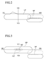
- automobile head lamps 100 are generally mounted to left and right sides of front portions of an automobile 300, e.g., on front bumper sides separately from automobile head lamps 200.
- the automobile head lamps 100 light up when a blinker switch is ON and a steering wheel is being operated, a light distribution pattern BP for bend beam shown in Figs. 2 and 3 is obtained, and left and right sides of the automobile with respect to a direction of straight traveling of the automobile are illuminated.
- a light distribution pattern BP for bend beam is synthesized with right side of a light distribution pattern LP for low beam (dipped-beam) obtained by the automobile head lamp 200, and the right side of the automobile is illuminated. Further, as shown in Fig. 3, the light distribution pattern BP for bend beam is synthesized with right side of a light distribution pattern HP for high beam (traveling beam) obtained by the automobile head lamp 200, and the right side of the automobile is illuminated.
- the bend beam light distribution pattern BP is synthesized with the left side of the low beam light distribution pattern LP and the high beam light distribution pattern HP, and the left side of the automobile is illuminated.
- the light distribution patterns LP and HP shown in Figs. 2 and 3 are those under the keep to the left traffic, and under the keep to the right traffic, the light distribution patterns LP and HP are reversed left to right.
- the bend beam light distribution pattern BP and the low beam light distribution pattern LP are not easily synthesized due to variation in mounting precision.
- the bend beam should basically be located on the right side (or left side) of the low beam light distribution pattern LP as shown with dotted line in Fig. 2, but the bend beam light distribution pattern BP may be located at a position lower to the basic position in some cases. In such a case, the mounting position of the automobile bend lamp 100 is adjusted to obtain desired light distribution patterns LP and BP.
- auxiliary hot zone HZ' shown with broken line
- left and right sides of a hot zone HZ shown with solid line
- the bend beam light distribution pattern BP is located on the right side (or left wide) of the high beam light distribution pattern HP, the bend beam light distribution pattern BP for illuminating left or right side with respect to the direction of travel of the automobile 300 is visually obtrusive on the contrary at the time of medium speed or high speed running.
- the present invention provides an automobile lamp comprising a reflector for forming a light distribution pattern by reflecting light from a light source, an effective reflecting surface provided on the reflector for forming at least one of a low beam light distribution pattern and a high beam light distribution pattern, a non-effective reflecting surface provided on the reflector for forming at least one of a low bend beam light distribution pattern and a high bend beam light distribution pattern, a light source valve disposed on the reflector on the side of the non-effective reflecting surface, a movable shade disposed around the light source valve such that the movable shade can move between a first position and a second position, driving means for moving the movable shade between the first position and the second position, a first reflecting surface provided on the non-effective reflecting surface of the reflector for forming the low bend beam light distribution pattern with light from the light source valve when the movable shade moves to the first position, and a second reflecting surface provided on the non-effective reflecting surface of the reflector for forming the high bend beam light distribution pattern with light from
- the automobile bend lamp of the present invention is mounted to the reflector of the automobile head lamp, special space for mounting the bend lamp to the vehicle body is unnecessary, and the problem of limitation of the design of the automobile is solved.
- the automobile lamp of the invention can obtain the excellent spot-like high bend beam light distribution pattern HBP at the time of medium speed running by the second reflecting surface.
- FIG. 4 to 19 An embodiment of an automobile lamp of the present invention will be explained with reference to Figs. 4 to 19.
- the same symbols as those used in Figs. 1 to 3 designate the same members.
- This embodiment is used for a keep to the left traffic, but under the keep to the right traffic, the embodiment is reversed left to right.
- members are mounted to on the right side of the front portion of the automobile, and members mounted on the left side are symmetrical with those mounted to the right side.
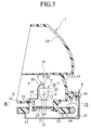
- a symbol 1 represents a reflector of an automobile head lamp.
- the automobile head lamp in this embodiment is a "front lamp" of Japanese Patent Application Laid-open No. H11-50875 (not Prior Art) for example, and is a double-lamp type head lamp using a discharge lamp (high pressure metal vapor discharge lamp, high illumination discharge lamp (HID) or the like such as metal halide lamp) as a light source valve.
- the reflector 1 includes an effective reflecting surface 10 forming a low beam light distribution pattern LP and a high beam light distribution pattern HP, and a non-effective reflecting surface 13 which is not used.
- the effective reflecting surface 10 is formed on substantially upper half of the reflector 1, and comprises a compound reflection surface for controlling the light distribution patterns LP and HP. Details of the compound reflecting surface are described in Japanese Patent Application Laid-open No. H9-306220.
- the non-effective reflecting surface 13 is formed on substantially lower half of the reflector 1. As shown in Fig. 5, a central partition wall 19 is integrally formed between the effective reflecting surface 10 and the non-effective reflecting surface 13.
- the reflector 1 is disposed in a lamp chamber (not shown) partitioned by a lamp housing (not shown) and a front lens (not shown) of the automobile head lamp, and is mounted to the lamp housing through an optical axis adjusting mechanism (not shown) such that the optical axis can be adjusted in the vertical and lateral directions.
- the reflector 1 is provided at its substantially central portion with a circle through hole 14. A discharge lamp (not shown) is inserted through the through hole 14, and this discharge lamp is detachable mounted to the reflector 1.
- the non-effective reflecting surface 13 of the reflector 1 is formed in a range comprising portions 130 (shaded areas in Fig. 7) which are light-shielded by cut line stripe of the discharge lamp (band-like coating or the like coated on a glass valve (outer tube) of the discharge lamp) and a portion 131 which is light-shielded by a shade (not shown).
- the non-effective reflecting surface 13 is formed in a range surrounded by thick solid line in Fig. 8.
- a first reflecting surface 11 and a second reflecting surface 12 are provided in the non-effective reflecting surface 13 of the reflector 1.
- the first reflecting surface 11 forms a low bend beam light distribution pattern LBP shown with thick solid line in Fig. 15, and the first reflecting surface 11 is provided utilizing a rising wall 15 of inner side L-IN of the automobile. As shown with solid arrows in Fig. 9, this is because it is possible to illuminate side of an outer side R-OUT of the automobile over a wide range, and this is most suitable for forming the low bend beam light distribution pattern LBP (see Fig. 15) for illuminating the side over the wide range. As shown in Fig.
- the first reflecting surface 11 forms a diverging type free curved surface in which the optical axis ZL-ZL is inclined at about 35° to 45°, and more preferably about 40° toward the outer side R-OUT with respect to the traveling direction ZF-ZB of the automobile.
- the second reflecting surface 12 forms a spot-like high bend beam light distribution pattern HBP, and is provided outer side R-OUT with respect to the first reflecting surface 11.
- the second reflecting surface 12 forms a paraboloid or free curved surface in which the optical axis ZH-ZH is inclined at about 5° with respect to the traveling direction ZF-ZB.
- optical axis ZL-ZL of the first reflecting surface 11 and the optical axis ZH-ZH pass through a center axis O-O of the light source valve 2.
- the symbol 2 represents the light source valve.
- the light source valve 2 is a halogen lamp of C-6 type, and comprises a glass valve 20 and a pinch portion 21, a filament 22 inserted into the center axis O-O of the light source valve 2 of the glass valve 20 perpendicularly, and a mounting brim 23 fixed to the pinch portion 21.
- the light source valve 2 is disposed on the side of the non-effective reflecting surface 13 of the reflector 1.
- the light source valve 2 is inserted toward the non-effective reflecting surface 13 from a mounting hole 17 provided in a bottom wall 16 of the reflector 1 perpendicularly, and the light source valve 2 is detachably mounted to the reflector 1 through the mounting brim 23.
- the mounting hole 17 By mounting the mounting hole 17 to the bottom wall 16 of the reflector 1, there is not reflection surface loss by the mounting hole 17 in the first reflecting surface 11 and the second reflecting surface 12 on the side of the non-effective reflecting surface 13.
- the center axis O-O of the light source valve 2 is substantially in parallel to the vertical axis VU-VD, and an axis Z-Z of the filament 22 of the light source valve 2 is substantially in parallel to the horizontal axes HL-HR and HR-HL.
- the axis Z-Z is inclined at ⁇ ° (about 60°) toward the outside R-OUT with respect to the traveling direction ZF-ZB of the automobile.
- a reflection image 24 of the filament 22 in the first reflecting surface 11 is long in its longitudinal direction as shown in Fig. 12, and this is most suitable for forming the low bend beam light distribution pattern LBP (see Fig. 15) for illuminating the side over the wide range.
- a reflection image 25 of the filament 22 in the second reflecting surface 12 is long in its lateral direction as shown in Fig. 13, and this is most suitable for forming the high bend beam light distribution pattern HBP (see Fig. 18) for illuminating in the spot-like manner.
- a symbol 3 represents a movable shade.
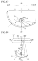
- the movable shade 3 is disposed such that it can move between a first position (position shown in Figs. 4, 5, 6, 14 and 15) and a second position (position shown in Figs. 17 and 18) around the light source valve 2, i.e., such that it can rotate around the center axis O-O of the light source valve 2.
- the movable shade 3 integrally comprises a dome-like shade portion 30 and a leg portion 31.
- the shade portion 30 covers the periphery of the light source valve 2.
- the leg portion 31 is fixed to a turning table 43 (which will be described later) through an arc groove 18 formed in the bottom wall 16 of the reflector 1.
- the shade portion 30 of the movable shade 3 is provided with a projection light opening 32.
- the opening 32 is opened such that when the opening 32 of the shade portion 30 of the movable shade 3 is located at the first position, light from the light source valve 2 is emitted to the first reflecting surface 11 as shown with solid arrows in Figs. 14 and 15, and when the shade portion 30 of the movable shade 3 is located at the second position, the light from the light source valve 2 is emitted to the second reflecting surface 12 as shown with solid arrows in Figs. 17 and 18.
- a symbol 4 represents driving means.
- the driving means 4 is for moving the movable shade 3 between the first and second positions, and comprises a mounting bracket 41 fixed to the reflector 1 by means of a screw 40 or the like, a motor 42 fixed to the mounting bracket 41, and the turning table 43 supported on the mounting bracket 41 such that the turning table 43 can rotate around the center axis Z-Z of the light source valve 2.
- a worm 44 fixed to the rotation shaft of the motor 42 and the teeth 45 mounted on an outer peripheral surface of the turning table 43 are meshed with each other.
- the light source valve 2, the movable shade 3 and the driving means 4 are formed as one unit and mounted to the reflector 1.
- the light source valve 2 and the motor 42 are connected to a blinder switch (not shown), a steering sensor (not shown) and a vehicle speed sensor and the like through a control section (not shown). Under the conditions shown in the following Table 1 and the operation pattern, the light source valve 2 lights up by the control section and at the same time, the motor 42 is rotated in the normal direction to move the movable shade 3 from the second position to the first position, and when the movable shade 3 moves to the first position, the normal rotation of the motor 42 is stopped or the motor 42 is rotated reversely, and the movable shade 3 moves from the first position to the second position, and when the movable shade 3 moves to the second position, the reverse rotation of the motor 42 is stopped.
- an operation pattern 1 is a pattern before an intersection for turning to the left or right for example.
- the automobile is running at a low speed, the steering wheel is not operated, the blinker switch is ON, and the movable shade 3 is located at the first position.
- An operation pattern 2 is a pattern when the automobile is on a curve in urban area for example. In this case, the automobile is running at a low speed, the steering wheel is being operated, the blinker switch is OFF, and the movable shade 3 is located at the first position.
- An operation pattern 3 is a pattern when the automobile is on a curve in suburban area for example. In this case, the automobile is running at a medium speed, the steering wheel is being operated, the blinker switch is OFF, and the movable shade 3 is located at the first position.
- An operation pattern 4 is a pattern when the automobile makes a lane change in suburban area for example.
- the automobile is running at a medium speed, the steering wheel is not operated, the blinker switch is ON, and the movable shade 3 is located at the second position.
- An operation pattern 5 is a pattern when the automobile is on a curve on an expressway for example. In this case, the automobile is running at a high speed, the steering wheel is being operated, the blinker switch is OFF, and the movable shade 3 is located at the second position.
- an operation pattern 6 is a pattern when the automobile makes a lane change on an expressway for example.
- the automobile is running at a high speed, the steering wheel is not operated, the blinker switch is ON, and the movable shade 3 is located at the second position.
- Pattern Vehicle speed Steering operation Blinker switch Position of movable shade Low speed Not operated ON First position 2 Low speed Being operated OFF First position 3 Medium speed Being operated OFF First position 4 Medium speed Not operated ON Second position 5 High speed Not operated ON Second position 6 High speed Being operated OFF Second position
- the movable shade 3 is located at the first position.
- the light from the light source valve 2 is reflected by the first reflecting surface as shown in Figs. 14 and 15, and illuminates the outer side R-OUT of the automobile as the low bend beam light distribution pattern LBP illuminating the side over the wide range.
- the low bend beam light distribution pattern LBP shown in Figs. 15 and 16B is synthesized on the right side of the low beam light distribution pattern LP, and the light distribution patterns LP and LBP shown in Figs. 15 and 16C can be obtained as a whole.
- the movable shade 3 is located at the second position.
- the light from the light source valve 2 is reflected on the second reflecting surface as shown in Figs. 17 and 18, and illuminates front of the automobile as the spot-like high bend beam light distribution pattern HBP.
- the spot-like high bend beam light distribution pattern HBP shown in Figs. 18 and 19B is synthesized on the right side of the hot zone HZ of the high beam light distribution pattern HP shown in Figs. 18 and 19A, and the light distribution patterns HP and HBP shown in Figs. 18 and 19C can be obtained as a whole.
- the low bend beam light distribution pattern LBP emitted from the automobile bend lamp mounted on the left side of the front portion of the automobile is synthesized on the left side of the low beam light distribution pattern LP
- the high bend beam light distribution pattern HBP is synthesized on the left side of the hot zone HZ of the high beam light distribution pattern HP.
- the automobile bend lamp of the present invention in this embodiment is mounted to the reflector 1 of the automobile head lamp, special space for mounting the bend lamp to the vehicle body is unnecessary, and the problem of limitation of the design of the automobile is solved.
- the automobile lamp of the invention in this embodiment can obtain the excellent spot-like high bend beam light distribution pattern HBP at the time of medium speed running by the second reflecting surface 12.
- the automobile head lamp is a double-lamp type head lamp using a discharge lamp, the lamp has small power consumption, high wattage valve can be used as the light source valve 2 of the automobile bend lamp of the automobile lamp of the invention, and sufficient illumination amount can be obtained correspondingly.
- the automobile bend lamp in the automobile lamp of the invention can also be applied to another automobile head lamp, e.g., a lamp using a halogen lamp as light source, and a four-lamp type lamp.
- the first reflecting surface 11 forming the low bend beam light distribution pattern LBP is provided utilizing the rising wall 15 of the inner side L-IN of the automobile among the reflector 1. Therefore, it is possible to illuminate the side of the outer side R-OUT of the automobile over the wide range, and this is most suitable for forming the low bend beam light distribution pattern LBP for illuminating the side over the wide range.
- the light source valve 2, the movable shade 3 and the driving means 4 are formed as one unit and mounted to the reflector 1. Therefore, the automobile bend lamp of the invention can easily be mounted to the automobile head lamp with high precision.
Landscapes
- Engineering & Computer Science (AREA)
- General Engineering & Computer Science (AREA)
- Mechanical Engineering (AREA)
- Non-Portable Lighting Devices Or Systems Thereof (AREA)
- Lighting Device Outwards From Vehicle And Optical Signal (AREA)
Applications Claiming Priority (2)
| Application Number | Priority Date | Filing Date | Title |
|---|---|---|---|
| JP2000045161A JP2001229711A (ja) | 2000-02-17 | 2000-02-17 | 自動車用ベンドランプ |
| JP2000045161 | 2000-02-17 |
Publications (3)
| Publication Number | Publication Date |
|---|---|
| EP1125792A2 true EP1125792A2 (de) | 2001-08-22 |
| EP1125792A3 EP1125792A3 (de) | 2003-09-17 |
| EP1125792B1 EP1125792B1 (de) | 2005-09-21 |
Family
ID=18567794
Family Applications (1)
| Application Number | Title | Priority Date | Filing Date |
|---|---|---|---|
| EP01102917A Expired - Lifetime EP1125792B1 (de) | 2000-02-17 | 2001-02-07 | Fahrzeugscheinwerfer |
Country Status (5)
| Country | Link |
|---|---|
| US (1) | US6508575B2 (de) |
| EP (1) | EP1125792B1 (de) |
| JP (1) | JP2001229711A (de) |
| KR (1) | KR100478298B1 (de) |
| DE (1) | DE60113467T2 (de) |
Cited By (5)
| Publication number | Priority date | Publication date | Assignee | Title |
|---|---|---|---|---|
| FR2902491A1 (fr) * | 2006-06-19 | 2007-12-21 | Valeo Vision Sa | Projecteur a plusieurs fonctions d'eclairage, en particulier pour vehicule automobile. |
| GB2453037A (en) * | 2007-09-20 | 2009-03-25 | Porsche Ag | An arrangement for the total reflection of light. |
| FR2924485A1 (fr) * | 2007-12-03 | 2009-06-05 | Valeo Vision Sa | Procede d'adaptation automatique aux conditions de circulation d'un faisceau lumineux de module optique, et projecteur associe |
| EP2551580A3 (de) * | 2011-07-26 | 2016-12-28 | Ichikoh Industries, Ltd. | Fahrzeugscheinwerfer |
| EP4324697A4 (de) * | 2021-04-12 | 2025-03-12 | Ichikoh Industries, Ltd. | Fahrzeuglampensteuerungsvorrichtung und fahrzeuglampe |
Families Citing this family (5)
| Publication number | Priority date | Publication date | Assignee | Title |
|---|---|---|---|---|
| US20040202004A1 (en) * | 2003-04-09 | 2004-10-14 | Guide Corporation, A Delaware Corporation | Bifunctional headlamp having a rotating shield with integral actuator |
| US7036969B2 (en) * | 2003-12-04 | 2006-05-02 | Guide Corporation | Adverse weather headlamp system |
| US7290907B2 (en) * | 2006-02-24 | 2007-11-06 | Honda Motor Co., Ltd | Vehicle headlamp with daytime running light |
| RU177050U1 (ru) * | 2017-07-21 | 2018-02-07 | Общество с ограниченной ответственностью "Лайт Трейдинг Рус" | Фара дальнего света |
| RU177029U1 (ru) * | 2017-07-21 | 2018-02-06 | Общество с ограниченной ответственностью "Лайт Трейдинг Рус" | Фара ближнего света |
Citations (2)
| Publication number | Priority date | Publication date | Assignee | Title |
|---|---|---|---|---|
| JPH09306220A (ja) | 1996-05-09 | 1997-11-28 | Ichikoh Ind Ltd | 車両用灯具のリフレクタ |
| JPH1150875A (ja) | 1997-08-01 | 1999-02-23 | Nissan Motor Co Ltd | 車両用ブレーキ装置 |
Family Cites Families (19)
| Publication number | Priority date | Publication date | Assignee | Title |
|---|---|---|---|---|
| JPH0227445Y2 (de) * | 1985-01-31 | 1990-07-25 | ||
| US4663696A (en) * | 1985-01-31 | 1987-05-05 | Koito Siesakusho Co., Ltd. | Dual purpose lamp assembly for use, for example, as a combined fog and cornering lamp on a motor vehicle |
| DE3826988A1 (de) * | 1988-08-09 | 1990-02-15 | Kodak Ag | Fahrzeugscheinwerfer |
| US5264993A (en) * | 1990-01-30 | 1993-11-23 | Robert Bosch Gmbh | Headlamp for power vehicles |
| JPH05174602A (ja) * | 1991-12-17 | 1993-07-13 | Koito Mfg Co Ltd | 配光可変型前照灯 |
| FR2727497A1 (fr) * | 1994-11-30 | 1996-05-31 | Valeo Vision | Projecteur a elargissement de faisceau, notamment pour vehicule automobile |
| JP2955199B2 (ja) * | 1994-12-29 | 1999-10-04 | 本田技研工業株式会社 | 可変配光ヘッドランプ装置 |
| JP2626970B2 (ja) * | 1995-04-28 | 1997-07-02 | 株式会社小糸製作所 | 車輌用ランプシステム |
| JP3133244B2 (ja) * | 1995-12-18 | 2001-02-05 | 株式会社小糸製作所 | 車輌用前照灯 |
| JP3165034B2 (ja) * | 1996-06-13 | 2001-05-14 | 株式会社小糸製作所 | 車輌用補助前照灯 |
| JP3165038B2 (ja) * | 1996-07-25 | 2001-05-14 | 株式会社小糸製作所 | 車輌用前照灯 |
| DE19639526A1 (de) * | 1996-09-26 | 1998-04-02 | Hella Kg Hueck & Co | Verfahren zur Anpassung eines Fahrzeuglichtes und Scheinwerfereinheit |
| FR2759651B1 (fr) * | 1997-02-18 | 1999-03-19 | Renault | Projecteur de vehicule automobile comportant un reflecteur fractionne en lames orientables |
| FR2760069B1 (fr) * | 1997-02-21 | 1999-05-14 | Valeo Vision | Systeme d'eclairage a projecteurs de faisceau proche de type code et de faisceau complementaire de virage |
| JP2000100233A (ja) * | 1998-09-25 | 2000-04-07 | Ichikoh Ind Ltd | 前照灯 |
| AT3835U1 (de) * | 1998-09-28 | 2000-08-25 | Zizala Lichtsysteme Gmbh | Kfz-scheinwerfer |
| JP4285716B2 (ja) * | 1999-03-26 | 2009-06-24 | 株式会社小糸製作所 | 車輌用前照灯装置 |
| DE19933662B4 (de) * | 1999-07-17 | 2011-12-22 | Automotive Lighting Reutlingen Gmbh | Scheinwerfer für Fahrzeuge für Abblendlicht und wenigstens eine weitere Lichtfunktion |
| JP2001158288A (ja) * | 1999-12-03 | 2001-06-12 | Ichikoh Ind Ltd | 自動車用ヘッドランプ |
-
2000
- 2000-02-17 JP JP2000045161A patent/JP2001229711A/ja active Pending
-
2001
- 2001-01-04 KR KR10-2001-0000320A patent/KR100478298B1/ko not_active Expired - Fee Related
- 2001-02-07 EP EP01102917A patent/EP1125792B1/de not_active Expired - Lifetime
- 2001-02-07 DE DE60113467T patent/DE60113467T2/de not_active Expired - Fee Related
- 2001-02-08 US US09/778,757 patent/US6508575B2/en not_active Expired - Fee Related
Patent Citations (2)
| Publication number | Priority date | Publication date | Assignee | Title |
|---|---|---|---|---|
| JPH09306220A (ja) | 1996-05-09 | 1997-11-28 | Ichikoh Ind Ltd | 車両用灯具のリフレクタ |
| JPH1150875A (ja) | 1997-08-01 | 1999-02-23 | Nissan Motor Co Ltd | 車両用ブレーキ装置 |
Cited By (8)
| Publication number | Priority date | Publication date | Assignee | Title |
|---|---|---|---|---|
| FR2902491A1 (fr) * | 2006-06-19 | 2007-12-21 | Valeo Vision Sa | Projecteur a plusieurs fonctions d'eclairage, en particulier pour vehicule automobile. |
| EP1870634A1 (de) * | 2006-06-19 | 2007-12-26 | Valeo Vision | Scheinwerfer mit mehreren Leuchtfunktionen, insbesondere für Kraftfahrzeuge |
| GB2453037A (en) * | 2007-09-20 | 2009-03-25 | Porsche Ag | An arrangement for the total reflection of light. |
| FR2924485A1 (fr) * | 2007-12-03 | 2009-06-05 | Valeo Vision Sa | Procede d'adaptation automatique aux conditions de circulation d'un faisceau lumineux de module optique, et projecteur associe |
| EP2068071A1 (de) * | 2007-12-03 | 2009-06-10 | Valeo Vision | Verfahren zur automatischen Anpassung des Lichtstrahls eines optischen Moduls an die Bedingungen des Straßenverkehrs, und entsprechender Fahrzeugscheinwerfer |
| EP2551580A3 (de) * | 2011-07-26 | 2016-12-28 | Ichikoh Industries, Ltd. | Fahrzeugscheinwerfer |
| EP4324697A4 (de) * | 2021-04-12 | 2025-03-12 | Ichikoh Industries, Ltd. | Fahrzeuglampensteuerungsvorrichtung und fahrzeuglampe |
| US12459424B2 (en) | 2021-04-12 | 2025-11-04 | Ichikoh Industries, Ltd. | Vehicle lamp control device, and vehicle lamp |
Also Published As
| Publication number | Publication date |
|---|---|
| DE60113467T2 (de) | 2006-06-29 |
| JP2001229711A (ja) | 2001-08-24 |
| EP1125792B1 (de) | 2005-09-21 |
| EP1125792A3 (de) | 2003-09-17 |
| DE60113467D1 (de) | 2006-02-02 |
| US20010021111A1 (en) | 2001-09-13 |
| US6508575B2 (en) | 2003-01-21 |
| KR100478298B1 (ko) | 2005-03-24 |
| KR20010081988A (ko) | 2001-08-29 |
Similar Documents
| Publication | Publication Date | Title |
|---|---|---|
| JP5398507B2 (ja) | 車両用前照灯装置 | |
| US20070195543A1 (en) | Vehicle headlamp | |
| US7575353B2 (en) | Drum-type movable light shielding plate and lighting device using the same | |
| JP2000195312A (ja) | 種々の特性を有する光束を発生するための車両用ヘッドライト装置 | |
| US6508575B2 (en) | Lamp for automobile | |
| FR2827945B1 (fr) | Projecteur elliptique equipe de caches a axes de pivotement transversaux pour vehicule automobile | |
| JP3989014B2 (ja) | 自動車用ヘッドランプ | |
| JP2002304905A (ja) | 車両用灯具 | |
| JP2002367416A (ja) | ヘッドランプ | |
| US6102557A (en) | Headlamp with auxiliary reflector | |
| JP2003187612A (ja) | 車両用灯具 | |
| JP5478144B2 (ja) | 車両用前照灯 | |
| US6533443B2 (en) | Head lamp for automobile | |
| JP2003317510A (ja) | 車両用灯具 | |
| JP3207529B2 (ja) | 配光可変型前照灯 | |
| JP2009211964A (ja) | 車両用ランプシステム | |
| JP2001351411A (ja) | 自動車用フォグランプ | |
| JP2579255Y2 (ja) | 光束パターン可変型4灯式前照灯 | |
| KR100486337B1 (ko) | 자동차용 헤드램프 | |
| EP1724519B1 (de) | Kfz-Scheinwerfergerät | |
| JP2002289008A (ja) | 車両用前照灯 | |
| JP2003249106A (ja) | 車両用灯具 | |
| JP4975388B2 (ja) | 車両用前照灯 | |
| JP2000353412A (ja) | ヘッドランプ | |
| JP2817603B2 (ja) | 補助照明装置 |
Legal Events
| Date | Code | Title | Description |
|---|---|---|---|
| PUAI | Public reference made under article 153(3) epc to a published international application that has entered the european phase |
Free format text: ORIGINAL CODE: 0009012 |
|
| 17P | Request for examination filed |
Effective date: 20010207 |
|
| AK | Designated contracting states |
Kind code of ref document: A2 Designated state(s): AT BE CH CY DE DK ES FI FR GB GR IE IT LI LU MC NL PT SE TR |
|
| AX | Request for extension of the european patent |
Free format text: AL;LT;LV;MK;RO;SI |
|
| PUAL | Search report despatched |
Free format text: ORIGINAL CODE: 0009013 |
|
| AK | Designated contracting states |
Kind code of ref document: A3 Designated state(s): AT BE CH CY DE DK ES FI FR GB GR IE IT LI LU MC NL PT SE TR |
|
| AX | Request for extension of the european patent |
Extension state: AL LT LV MK RO SI |
|
| 17Q | First examination report despatched |
Effective date: 20040421 |
|
| AKX | Designation fees paid |
Designated state(s): DE FR GB |
|
| GRAP | Despatch of communication of intention to grant a patent |
Free format text: ORIGINAL CODE: EPIDOSNIGR1 |
|
| RIC1 | Information provided on ipc code assigned before grant |
Ipc: 7F 21V 7/00 B Ipc: 7F 21V 14/08 B Ipc: 7F 21V 14/04 B Ipc: 7B 60Q 1/12 A |
|
| GRAS | Grant fee paid |
Free format text: ORIGINAL CODE: EPIDOSNIGR3 |
|
| GRAA | (expected) grant |
Free format text: ORIGINAL CODE: 0009210 |
|
| AK | Designated contracting states |
Kind code of ref document: B1 Designated state(s): DE FR GB |
|
| REG | Reference to a national code |
Ref country code: GB Ref legal event code: FG4D |
|
| REF | Corresponds to: |
Ref document number: 60113467 Country of ref document: DE Date of ref document: 20051027 Kind code of ref document: P |
|
| REF | Corresponds to: |
Ref document number: 60113467 Country of ref document: DE Date of ref document: 20060202 Kind code of ref document: P |
|
| PGFP | Annual fee paid to national office [announced via postgrant information from national office to epo] |
Ref country code: FR Payment date: 20060217 Year of fee payment: 6 |
|
| PGFP | Annual fee paid to national office [announced via postgrant information from national office to epo] |
Ref country code: DE Payment date: 20060330 Year of fee payment: 6 |
|
| ET | Fr: translation filed | ||
| PLBE | No opposition filed within time limit |
Free format text: ORIGINAL CODE: 0009261 |
|
| STAA | Information on the status of an ep patent application or granted ep patent |
Free format text: STATUS: NO OPPOSITION FILED WITHIN TIME LIMIT |
|
| 26N | No opposition filed |
Effective date: 20060622 |
|
| GBPC | Gb: european patent ceased through non-payment of renewal fee |
Effective date: 20070207 |
|
| REG | Reference to a national code |
Ref country code: FR Ref legal event code: ST Effective date: 20071030 |
|
| PG25 | Lapsed in a contracting state [announced via postgrant information from national office to epo] |
Ref country code: DE Free format text: LAPSE BECAUSE OF NON-PAYMENT OF DUE FEES Effective date: 20070901 |
|
| PG25 | Lapsed in a contracting state [announced via postgrant information from national office to epo] |
Ref country code: GB Free format text: LAPSE BECAUSE OF NON-PAYMENT OF DUE FEES Effective date: 20070207 Ref country code: FR Free format text: LAPSE BECAUSE OF NON-PAYMENT OF DUE FEES Effective date: 20070228 |
|
| PGFP | Annual fee paid to national office [announced via postgrant information from national office to epo] |
Ref country code: GB Payment date: 20060208 Year of fee payment: 6 |