EP1125799A2 - Druckablasssystem für ein Fahrzeugpedal - Google Patents
Druckablasssystem für ein Fahrzeugpedal Download PDFInfo
- Publication number
- EP1125799A2 EP1125799A2 EP01300966A EP01300966A EP1125799A2 EP 1125799 A2 EP1125799 A2 EP 1125799A2 EP 01300966 A EP01300966 A EP 01300966A EP 01300966 A EP01300966 A EP 01300966A EP 1125799 A2 EP1125799 A2 EP 1125799A2
- Authority
- EP
- European Patent Office
- Prior art keywords
- vehicle
- pedal
- fluid
- pressure release
- deceleration
- Prior art date
- Legal status (The legal status is an assumption and is not a legal conclusion. Google has not performed a legal analysis and makes no representation as to the accuracy of the status listed.)
- Withdrawn
Links
Images


Classifications
-
- G—PHYSICS
- G05—CONTROLLING; REGULATING
- G05G—CONTROL DEVICES OR SYSTEMS INSOFAR AS CHARACTERISED BY MECHANICAL FEATURES ONLY
- G05G1/00—Controlling members, e.g. knobs or handles; Assemblies or arrangements thereof; Indicating position of controlling members
- G05G1/30—Controlling members actuated by foot
- G05G1/32—Controlling members actuated by foot with means to prevent injury
-
- B—PERFORMING OPERATIONS; TRANSPORTING
- B60—VEHICLES IN GENERAL
- B60T—VEHICLE BRAKE CONTROL SYSTEMS OR PARTS THEREOF; BRAKE CONTROL SYSTEMS OR PARTS THEREOF, IN GENERAL; ARRANGEMENT OF BRAKING ELEMENTS ON VEHICLES IN GENERAL; PORTABLE DEVICES FOR PREVENTING UNWANTED MOVEMENT OF VEHICLES; VEHICLE MODIFICATIONS TO FACILITATE COOLING OF BRAKES
- B60T7/00—Brake-action initiating means
- B60T7/02—Brake-action initiating means for personal initiation
- B60T7/04—Brake-action initiating means for personal initiation foot actuated
- B60T7/06—Disposition of pedal
- B60T7/065—Disposition of pedal with means to prevent injuries in case of collision
Definitions
- the present invention generally relates to vehicle pedal assemblies, and more particularly, to a pedal assembly, such as a brake pedal assembly, that is releasable from an operative condition upon imposition of a frontal load to an automotive vehicle.
- foot pedal assemblies such as the brake pedal assembly which is generally positioned below the instrument panel of the vehicle in the driver's compartment, may transfer collision caused intrusive forces to the driver's leg. This is because in a severe frontal collision, deformation of the vehicle dash panel can cause the foot pedal assembly to move rearward toward the vehicle occupants. In addition, this rearward translation is often accompanied by some degree of rotation about a lateral axis of the mounting plane of the pedal assembly. Likewise, the reaction of the occupant in the collision can force the occupant's legs into the food pedal controls.
- Foot pedal assemblies employed with hydraulic fluid actuated systems, such as the brake pedal assembly, generally have a foot pedal pad connected to a lever and a piston push rod, with assist from a vacuum booster, that compresses a master cylinder which in turn generates hydraulic fluid pressure.
- the hydraulic resistance in the master cylinder applied against the brake pedal assembly may in some instances cause the brake pedal to inflict injury to the driver's legs.
- the hydraulic resistance in the master cylinder may cause the brake pedal to damage lower extremities of the occupant due to the reaction of the occupant in a collision, independent of the dash and pedal intrusion forces.
- One approach to minimising such forces during a severe frontal collision includes structurally connecting the pedal box assembly to a cowl structure which remains relatively stable relative to the dash panel. With the pedal box assembly structurally connected to the cowl structure, relative movement can be made to cause a failure in the structure supporting the pivots of the pedal box assembly, thus allowing the pedals to move freely with little constraint following a severe frontal collision.
- Other approaches have included the use of mechanical connections, such as a cable, between the cowl, or some other relatively stable structure, and the pedal box. With these approaches, the deflection of the pedal assembly relative to the stable structure during a severe frontal collision is used to actively depress the pedal through the action of the aforementioned mechanical connection.
- the aforementioned approaches significantly increase the cost and complexity of the pedal box assembly, and may render the pedal assemblies inoperative following a vehicle collision.
- a releasable pedal system such as a brake pedal system, for a vehicle which reduces forces, such as intrusion forces, applied to the pedal system during a vehicle collision.
- the pedal system includes a pedal assembly that is operatively engageable by an occupant of the vehicle, and an actuator assembly for generating an amount of pressurised fluid.
- the releasable pedal system further includes a pressure release valve coupled in fluid communication with the pressurised fluid. The pressure release valve is operative to reduce the amount of pressurised fluid during a detected vehicle deceleration indicative of a vehicle collision. Accordingly, the releasable pedal system of the present invention advantageously reduces the forces transferred to the pedal assembly during a collision.
- a hydraulic brake system 10 is shown according to one embodiment of the present invention for use in braking a vehicle, such as an automobile.
- the brake system 10 has a brake pedal assembly 12 generally located in the passenger compartment, generally defined rearward of a dash panel in the vehicle.
- the brake pedal assembly 12 includes an elongated pedal 14 pivotally mounted at its upper end to a pivotal connection 18 which in turn is generally rigidly secured to the dash panel.
- Proximate the lower end of the pedal 14 is a pedal pad 16 which is configured to be operatively engageable with the foot of the vehicle operator, i.e., driver, to pivot the pedal 14 clockwise as shown in FIG. 1 to actuate the braking system.
- the brake pedal assembly 12 further includes a piston push rod 22 assembled to pedal 14. Push rod 22 is axially movable in co-operation with pedal 14 and operatively engages a brake actuator assembly 20.
- the brake actuator assembly 20 is equipped with a vacuum booster 24, a brake master cylinder 26, and a hydraulic fluid storage reservoir 28.
- Storage reservoir 28 contains a reserve of non-pressurised hydraulic brake fluid.
- the vacuum booster 24 provides assist to the piston push rod 22 to actuate the master cylinder 26.
- the master cylinder 26, in co-operation with the vacuum booster 24, generates a controlled amount of hydraulic fluid pressure in response to axial movement of piston push rod 22, which in turn is responsive to operator actuation of pedal pad 16, as is generally known in the art.
- the brake actuator assembly 20 made up of vacuum booster 24, master cylinder 26 and reservoir 28, as well as the brake pedal assembly 12 made up of pedal 14, pedal pad 16 and push rod 22, may include conventional brake system assemblies.
- the vehicle brake system 10 is shown having four brakes including the right front brake 44A, left front brake 44B, left rear brake 44C, and right rear brake 44D, according to one example.
- Brakes 44A-44D provide friction braking to brake the corresponding wheels on the vehicle in response to the hydraulic fluid pressure generated by the actuator assembly 20.
- Each of brakes 44A-44D may include conventional brake assemblies made up of callipers/cylinders and brake pads as is commonly known in the vehicle brake art.
- primary and secondary brake hydraulic circuits 32 and 34 provide hydraulic brake fluid flow paths between the master cylinder 26 and each of brakes 44A-44D.
- hydraulic circuit 32 is coupled to brakes 44A and 44B, while hydraulic circuit 34 is coupled to brakes 44C and 44D.
- one or more hydraulic circuits may employed and may be otherwise connected to one or more brakes.
- the brake circuits could be diagonally biased, as is commonly known in the vehicle brake art.
- a brake fluid return line 36 is also provided to serve as a return path to allow brake fluid to be expelled from one or both of the brake hydraulic circuits 32 and 34 and returned to the brake fluid reservoir 28, according to one example.
- a pressure release valve 30 is employed in fluid communication with one or both of the primary and secondary brake hydraulic circuits 32 and 34 and is operative to reduce the brake fluid pressure during a vehicle collision.
- the pressure release valve 30 may be connected in series or otherwise tapped into one or both of hydraulic circuits 32 and 34.
- the pressure release valve 30 may include a solenoid operated, or otherwise actuated, hydraulic valve that is normally closed to prevent the release of hydraulic brake fluid pressure. It should be appreciated that pressure release valve 30 continuously allows hydraulic brake fluid flow between the master cylinder 26 and each of brakes 44A-44D, and preferably is operable only to discharge brake fluid to reduce brake fluid pressure during a vehicle collision.
- pressure release valve 30, when actuated to the open position during a vehicle collision, discharges brake fluid into the brake fluid reservoir 28 via return line 36. Accordingly, the discharged brake fluid is recovered and is reusable without introducing air into the brake circuits.
- Pressure release valve 30 is actuated to the open position to release brake fluid pressure in response to a sensed deceleration signal 38 indicative of a vehicle collision.
- the deceleration signal 38 may be generated by an air bag deceleration sensor 40 or an air bag activation signal.
- the air bag deceleration sensor 40 which is generally commonly available on many modern automotive vehicles equipped with air bags, senses vehicle deceleration to detect the occurrence of a vehicle collision event.
- the deceleration signal 38 generated by sensor 40 may be processed via optional signal conditioning circuitry 42, which may include a relay, a microprocessor, or other control device such as an air bag controller that generates an air bag activation signal.
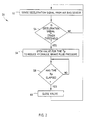
- the brake control methodology 50 includes step 52 of sensing a deceleration signal generated by an air bag deceleration sensor.
- Decision block 54 checks if the deceleration signal is greater than a crash threshold value and, if not, returns to step 52 to sense the deceleration signal from the air bag deceleration sensor. If the sensed deceleration signal is greater than the crash threshold value, methodology 50 proceeds to step 56 to open the pressure release valve 30 for a period of time T p to reduce hydraulic brake fluid pressure applied to the vehicle brakes. The temporary reduction of brake fluid pressure reduces the amount of intrusion forces that would otherwise be transferred to the brake pedal assembly.
- Decision block 58 checks for whether the pressure release time T p has elapsed.
- the pressure release time T p may be set to a time interval sufficient to mitigate negative effects on the vehicle occupant. Once the time period T p has elapsed, methodology 50 proceeds to step 60 to close the pressure release valve 30 to allow the brake system to resume normal braking operations. Following closure of the pressure release valve, methodology 50 returns back to step 52 to repeat the aforementioned steps, and therefore may again release brake fluid pressure upon detecting another vehicle collision.
- a mechanically actuated pressure release valve 30' is illustrated which may be employed in place of the solenoid actuated valve 30 and air bag deceleration sensor 40 with signal conditioning circuitry 42 described above, according to a second embodiment of the present invention.
- the mechanically actuated pressure release valve 30' has a built-in movable mass deceleration sensing mechanism that senses deceleration of the vehicle indicative of the imposition of a frontal load during a collision, and automatically opens the hydraulic fluid path between at least one of the primary and secondary brake hydraulic circuits 32 and 34 to the return line 36 to thereby reduce the amount of hydraulic fluid pressure applied to the vehicle brakes.
- the pressure relief valve 30' has a housing 70 formed with an inlet port 72 coupled to one of the brake hydraulic circuits, such as primary circuit 32, and a pressure release outlet port 74 that is shown coupled to return line 36.
- Housing 70 defines a container which houses a movable inertial mass 76.
- Inertial mass 76 is preferably cylindrical and has a pair of O-ring seals 78 and 80 spaced apart from each other on opposite ends of inertial mass 76 to define a fluid path 82 therebetween.
- Inertial mass 76 is movable along axis 88 which is substantially aligned with the longitudinal axis of the vehicle.
- Disposed between one end of housing 70 and one end of inertial mass 76 is a coil spring 84 and a stop member 86. Spring 84 biases the inertial mass 76 towards a normally closed position to prevent brake fluid flow between the inlet port 72 and outlet port 74.
- Inertial mass 76 is slidably movable along the axis 88 upon experiencing a sufficient amount of deceleration along the axis 88, which is generally indicative of a severe frontal collision of the vehicle.
- inertial mass 76 slidably moves from the normally closed position to a pressure release open position in which fluid path 82 is in fluid communication with both inlet port 72 and outlet port 74 as is shown in FIG. 4.
- the travel of inertial mass 76 to the fully open valve position is limited by stop member 86.
- Inertial mass 76 remains in the open valve pressure release position as long as the vehicle deceleration is of a sufficient amount.
- the pressure release valve 30' may serve to provide variable pressure release in which the amount of hydraulic fluid pressure released is a function of the vehicle deceleration. Accordingly, a greater vehicle deceleration may result is increased pressure release.
- valve 30' The pressure release fluid flow path through valve 30' in the open valve position is further shown in FIG. 5.
- hydraulic brake fluid is released from brake hydraulic circuit 32 via a fluid flow path through inlet port 72, fluid flow path 82, to outlet port 74, where it may be discharged to the brake fluid reservoir 28 via return line 36.
- brake fluid pressure is released from hydraulic circuit 32 via return line 36, it should be appreciated that the hydraulic brake fluid pressure may be released from one or both of hydraulic circuits 32 and 34 and discharged through other fluid paths.
- the brake pedal assembly advantageously is at least partially released upon imposition of a detected frontal load to the vehicle. While the present invention has been described herein in connection with reducing forces, such as intrusion forces, transferred through a hydraulic brake pedal assembly during a vehicle collision, it should be appreciated that the present invention may be used with other types of pedal assemblies to minimise adverse affects on the vehicle occupants. For example, the present invention may be used to reduce such forces transferred through a hydraulic clutch assembly pedal.
Landscapes
- Engineering & Computer Science (AREA)
- Physics & Mathematics (AREA)
- General Physics & Mathematics (AREA)
- Automation & Control Theory (AREA)
- Transportation (AREA)
- Mechanical Engineering (AREA)
- Regulating Braking Force (AREA)
- Mechanical Control Devices (AREA)
Applications Claiming Priority (2)
| Application Number | Priority Date | Filing Date | Title |
|---|---|---|---|
| US504416 | 2000-02-15 | ||
| US09/504,416 US6565160B1 (en) | 2000-02-15 | 2000-02-15 | Pressure releasable vehicle pedal assembly |
Publications (2)
| Publication Number | Publication Date |
|---|---|
| EP1125799A2 true EP1125799A2 (de) | 2001-08-22 |
| EP1125799A3 EP1125799A3 (de) | 2004-04-14 |
Family
ID=24006180
Family Applications (1)
| Application Number | Title | Priority Date | Filing Date |
|---|---|---|---|
| EP01300966A Withdrawn EP1125799A3 (de) | 2000-02-15 | 2001-02-02 | Druckablasssystem für ein Fahrzeugpedal |
Country Status (2)
| Country | Link |
|---|---|
| US (2) | US6565160B1 (de) |
| EP (1) | EP1125799A3 (de) |
Cited By (2)
| Publication number | Priority date | Publication date | Assignee | Title |
|---|---|---|---|---|
| FR2871760A1 (fr) * | 2004-06-16 | 2005-12-23 | Renault Sas | Dispositif de controle d'effort a la pedale de frein, notamment pour un systeme de freinage decouple |
| WO2007104629A1 (de) * | 2006-03-15 | 2007-09-20 | Robert Bosch Gmbh | Bremsanlage für ein fahrzeug |
Families Citing this family (10)
| Publication number | Priority date | Publication date | Assignee | Title |
|---|---|---|---|---|
| FR2829982B1 (fr) * | 2001-09-26 | 2004-01-23 | Bosch Gmbh Robert | Dispositif de freinage a securite accrue et systeme de freinage comportant un tel dispositif |
| US6695415B2 (en) * | 2002-04-04 | 2004-02-24 | Ford Global Technologies, Llc | Brake fluid pressure relief assembly |
| US7195091B2 (en) * | 2003-08-06 | 2007-03-27 | Drivesol Worldwide, Inc. | Crash relief pedal assembly |
| JP4670349B2 (ja) * | 2004-03-10 | 2011-04-13 | 株式会社アドヴィックス | 車両用制動装置 |
| US7987743B2 (en) * | 2008-12-19 | 2011-08-02 | Ventra Group, Inc. | Positive release crash pedal mechanism |
| US9523998B2 (en) | 2013-03-14 | 2016-12-20 | Ventra Group Co. | Safety release system for pedals |
| US9889826B2 (en) | 2014-02-19 | 2018-02-13 | Ventra Group Co. | Variable ratio brake pedal |
| US10252705B2 (en) * | 2017-01-30 | 2019-04-09 | Gulfstream Aerospace Corporation | System for controlling a wheel brake of an aircraft |
| IT201900025336A1 (it) * | 2019-12-23 | 2021-06-23 | Freni Brembo Spa | Un impianto frenante per veicoli con pedale di azionamento collassabile e il relativo metodo di azionamento di un impianto di frenatura in caso di urto |
| CN113931942B (zh) * | 2021-11-11 | 2024-07-16 | 江铃汽车股份有限公司 | 一种大吨位液刹商用车离合操纵助力系统 |
Family Cites Families (36)
| Publication number | Priority date | Publication date | Assignee | Title |
|---|---|---|---|---|
| JPS4820353B1 (de) * | 1968-06-22 | 1973-06-20 | ||
| US3664130A (en) * | 1970-11-16 | 1972-05-23 | Bendix Corp | Hydraulic brake pressure limiting device |
| US3945672A (en) | 1975-01-06 | 1976-03-23 | Wong Ngew Yee | Impact braking device |
| US4172603A (en) * | 1978-01-11 | 1979-10-30 | General Time Corporation | Sensing apparatus with mechanical actuation system |
| US4319455A (en) * | 1979-02-28 | 1982-03-16 | General Motors Corporation | Hydraulic power brake system and hydraulic brake booster and controls therefor |
| US4964485A (en) | 1989-04-18 | 1990-10-23 | Backstop, Inc. | Back-up safety device and method |
| US4971402A (en) * | 1989-09-12 | 1990-11-20 | Chen Teh Chih | Vehicle brake system with locking preventive mechanism |
| DE3941401C1 (de) * | 1989-12-15 | 1991-01-31 | Mercedes-Benz Aktiengesellschaft, 7000 Stuttgart, De | |
| US5249646A (en) | 1990-05-26 | 1993-10-05 | Alfred Teves Gmbh | Adjusting device for a brake with resetting means |
| US6078854A (en) * | 1995-06-07 | 2000-06-20 | Automotive Technologies International, Inc. | Apparatus and method for adjusting a vehicle component |
| DE4304565A1 (de) * | 1993-02-16 | 1994-08-18 | Teves Gmbh Alfred | Hydraulische Kraftfahrzeugbremsanlage |
| US5531135A (en) * | 1993-06-11 | 1996-07-02 | Volkswagon Ag | Pedal arrangement for a motor vehicle |
| FR2720046B1 (fr) * | 1994-05-20 | 1996-09-20 | Alliedsignal Europe Services Techniques | Maitre-cylindre a securite accrue |
| FR2721887B1 (fr) * | 1994-06-29 | 1996-09-06 | Alliedsignal Europ Services | Au freinage et d'un maitre-cylindre ensemble d'un servomoteur pneumatique d'assistance |
| JP3878229B2 (ja) * | 1994-08-24 | 2007-02-07 | 住友電気工業株式会社 | 車両の減速度制御装置 |
| JP3267082B2 (ja) * | 1994-12-28 | 2002-03-18 | トヨタ自動車株式会社 | 車両用ペダル装置 |
| FR2729355A1 (fr) * | 1995-01-18 | 1996-07-19 | Alliedsignal Europ Services | Ensemble d'un servomoteur pneumatique d'assistance au freinage et d'un maitre-cylindre |
| DE19506607A1 (de) * | 1995-02-24 | 1996-08-29 | Teves Gmbh Alfred | Kraftfahrzeug-Betätigungseinheit |
| DE19522398C1 (de) | 1995-06-23 | 1996-12-19 | Daimler Benz Ag | Sicherheitsanordnung im Fußraum eines Kraftwagens |
| DE19529347A1 (de) * | 1995-08-09 | 1997-02-20 | Hs Tech & Design | Vorrichtung zum Lösen der Verankerung eines Pedals vom Aufbau eines Kraftfahrzeugs |
| JP3463423B2 (ja) * | 1995-09-26 | 2003-11-05 | 日産自動車株式会社 | 乗員脱出支援装置 |
| US6364046B1 (en) * | 1996-01-30 | 2002-04-02 | Ab Volvo | Method for activation of a safety arrangement in a vehicle |
| DE19606427A1 (de) * | 1996-02-22 | 1997-08-28 | Teves Gmbh Alfred | Bremspedalwerk für Kraftfahrzeuge |
| JP3125677B2 (ja) | 1996-04-30 | 2001-01-22 | トヨタ自動車株式会社 | 車両用ペダル支持構造 |
| JP3267182B2 (ja) * | 1996-05-29 | 2002-03-18 | トヨタ自動車株式会社 | 車両用ペダル変位制御構造 |
| JP3277814B2 (ja) | 1996-06-27 | 2002-04-22 | トヨタ自動車株式会社 | 車両用ペダル変位制御構造 |
| DE19631212C1 (de) | 1996-08-02 | 1997-12-18 | Daimler Benz Ag | Fahrpedaleinheit |
| US5916330A (en) | 1997-01-15 | 1999-06-29 | Ford Global Technologies, Inc. | Cable operated releasable brake pedal assembly |
| FR2760218B1 (fr) * | 1997-02-28 | 1999-04-16 | Bosch Syst Freinage | Dispositif de freinage a zone de fragilite controlee |
| US5921144A (en) * | 1997-09-11 | 1999-07-13 | Chrysler Corporation | Brake pedal assembly with displacement limiter |
| FR2774642B1 (fr) * | 1998-02-11 | 2000-06-09 | Renault | Dispositif de limitation de l'effort sur la pedale de freinage d'un vehicule |
| US6309031B1 (en) * | 1999-12-14 | 2001-10-30 | Ford Global Technology, Inc. | Vehicle brake system with variable brake pedal feel |
| GB9930601D0 (en) * | 1999-12-24 | 2000-02-16 | Ksr Automotive Limited | Vehicle pedal box |
| WO2001066399A1 (en) * | 2000-03-06 | 2001-09-13 | Dong Ik Chi | Mechanical oil pressure control apparatus for antilock brake system |
| GB2345107B (en) * | 2000-03-18 | 2000-11-22 | Dura Automotive Ltd | Motor vehicle hydraulic braking systems |
| US6520044B1 (en) * | 2000-06-01 | 2003-02-18 | Acutex, Inc. | Brake pedal shock absorber and method |
-
2000
- 2000-02-15 US US09/504,416 patent/US6565160B1/en not_active Expired - Lifetime
-
2001
- 2001-02-02 EP EP01300966A patent/EP1125799A3/de not_active Withdrawn
-
2003
- 2003-02-03 US US10/248,638 patent/US6672682B2/en not_active Expired - Lifetime
Cited By (2)
| Publication number | Priority date | Publication date | Assignee | Title |
|---|---|---|---|---|
| FR2871760A1 (fr) * | 2004-06-16 | 2005-12-23 | Renault Sas | Dispositif de controle d'effort a la pedale de frein, notamment pour un systeme de freinage decouple |
| WO2007104629A1 (de) * | 2006-03-15 | 2007-09-20 | Robert Bosch Gmbh | Bremsanlage für ein fahrzeug |
Also Published As
| Publication number | Publication date |
|---|---|
| EP1125799A3 (de) | 2004-04-14 |
| US6565160B1 (en) | 2003-05-20 |
| US6672682B2 (en) | 2004-01-06 |
| US20030094852A1 (en) | 2003-05-22 |
Similar Documents
| Publication | Publication Date | Title |
|---|---|---|
| US5927821A (en) | Hydraulic automotive vehicle brake system | |
| JP3467339B2 (ja) | 車両の衝突状態制御システム | |
| US5791750A (en) | Arrangement for preventing a vehicle from rolling away | |
| US6364046B1 (en) | Method for activation of a safety arrangement in a vehicle | |
| US8016720B2 (en) | Hold function for temporarily holding an operationally ready motor vehicle in a stationary state | |
| US6786109B2 (en) | Safety device for supporting pedals | |
| US6565160B1 (en) | Pressure releasable vehicle pedal assembly | |
| US6290310B1 (en) | Brake pressure control device for automotive vehicles | |
| US7014006B2 (en) | System and method for minimizing injury after a loss of control event | |
| JP4794464B2 (ja) | 車輛の液圧式ブレーキシステム用の制動力発生器 | |
| US6286388B1 (en) | Vehicle pedal assembly | |
| US6893102B2 (en) | Safety braking device and a braking system comprising such device | |
| JP3275357B2 (ja) | ブレーキ装置 | |
| US6655230B1 (en) | Vehicle pedal assembly | |
| US6695415B2 (en) | Brake fluid pressure relief assembly | |
| KR100580508B1 (ko) | 운전자 보호장치 | |
| EP1339579B1 (de) | Bremsdruckbegrenzung | |
| GB2367870A (en) | Airbag or crash sensor activation of push-through backup mode in electro-hydraulic (EHB) braking systems | |
| GB2345107A (en) | Motor vehicle hydraulic braking systems | |
| KR100233604B1 (ko) | 시트벨트 홀딩장치 | |
| KR100521919B1 (ko) | 자동차용 브레이크 페달의 격납구조 | |
| JP3253039B2 (ja) | 車両用制動装置 | |
| KR100254356B1 (ko) | 차량의 충돌시 자동제동장치 | |
| KR0184824B1 (ko) | 푸트브레이크 오작동시의 안전장치 | |
| KR19980035964U (ko) | 에어 백 작동시 브레이크 위치 고정장치 |
Legal Events
| Date | Code | Title | Description |
|---|---|---|---|
| PUAI | Public reference made under article 153(3) epc to a published international application that has entered the european phase |
Free format text: ORIGINAL CODE: 0009012 |
|
| AK | Designated contracting states |
Kind code of ref document: A2 Designated state(s): AT BE CH CY DE DK ES FI FR GB GR IE IT LI LU MC NL PT SE TR |
|
| AX | Request for extension of the european patent |
Free format text: AL;LT;LV;MK;RO;SI |
|
| PUAL | Search report despatched |
Free format text: ORIGINAL CODE: 0009013 |
|
| AK | Designated contracting states |
Kind code of ref document: A3 Designated state(s): AT BE CH CY DE DK ES FI FR GB GR IE IT LI LU MC NL PT SE TR |
|
| AX | Request for extension of the european patent |
Extension state: AL LT LV MK RO SI |
|
| 17P | Request for examination filed |
Effective date: 20040904 |
|
| AKX | Designation fees paid |
Designated state(s): DE FR GB |
|
| 17Q | First examination report despatched |
Effective date: 20050705 |
|
| STAA | Information on the status of an ep patent application or granted ep patent |
Free format text: STATUS: THE APPLICATION IS DEEMED TO BE WITHDRAWN |
|
| 18D | Application deemed to be withdrawn |
Effective date: 20051116 |