EP1125885A2 - Ankerwinde - Google Patents
Ankerwinde Download PDFInfo
- Publication number
- EP1125885A2 EP1125885A2 EP00710043A EP00710043A EP1125885A2 EP 1125885 A2 EP1125885 A2 EP 1125885A2 EP 00710043 A EP00710043 A EP 00710043A EP 00710043 A EP00710043 A EP 00710043A EP 1125885 A2 EP1125885 A2 EP 1125885A2
- Authority
- EP
- European Patent Office
- Prior art keywords
- winch
- gear
- motor
- winch drum
- rope
- Prior art date
- Legal status (The legal status is an assumption and is not a legal conclusion. Google has not performed a legal analysis and makes no representation as to the accuracy of the status listed.)
- Granted
Links
- 230000002441 reversible effect Effects 0.000 claims description 15
- 238000011084 recovery Methods 0.000 claims description 8
- 230000002829 reductive effect Effects 0.000 claims description 2
- 230000004913 activation Effects 0.000 claims 2
- 230000014759 maintenance of location Effects 0.000 claims 1
- 230000005540 biological transmission Effects 0.000 description 9
- 238000000034 method Methods 0.000 description 8
- 238000013461 design Methods 0.000 description 3
- 238000005461 lubrication Methods 0.000 description 3
- 230000006835 compression Effects 0.000 description 2
- 238000007906 compression Methods 0.000 description 2
- 238000010586 diagram Methods 0.000 description 2
- 238000009434 installation Methods 0.000 description 2
- 238000012546 transfer Methods 0.000 description 2
- 238000009966 trimming Methods 0.000 description 2
- 206010011469 Crying Diseases 0.000 description 1
- 238000007792 addition Methods 0.000 description 1
- 238000005253 cladding Methods 0.000 description 1
- 238000010924 continuous production Methods 0.000 description 1
- 238000002788 crimping Methods 0.000 description 1
- 230000003247 decreasing effect Effects 0.000 description 1
- 230000002349 favourable effect Effects 0.000 description 1
- 230000001771 impaired effect Effects 0.000 description 1
- 230000000670 limiting effect Effects 0.000 description 1
- 239000000314 lubricant Substances 0.000 description 1
- 238000012423 maintenance Methods 0.000 description 1
- 239000000463 material Substances 0.000 description 1
- 230000036961 partial effect Effects 0.000 description 1
- 230000000737 periodic effect Effects 0.000 description 1
- 230000002035 prolonged effect Effects 0.000 description 1
- 230000001681 protective effect Effects 0.000 description 1
- 238000007789 sealing Methods 0.000 description 1
- 238000013519 translation Methods 0.000 description 1
- 238000004804 winding Methods 0.000 description 1
Images





Classifications
-
- B—PERFORMING OPERATIONS; TRANSPORTING
- B63—SHIPS OR OTHER WATERBORNE VESSELS; RELATED EQUIPMENT
- B63B—SHIPS OR OTHER WATERBORNE VESSELS; EQUIPMENT FOR SHIPPING
- B63B21/00—Tying-up; Shifting, towing, or pushing equipment; Anchoring
- B63B21/16—Tying-up; Shifting, towing, or pushing equipment; Anchoring using winches
-
- B—PERFORMING OPERATIONS; TRANSPORTING
- B66—HOISTING; LIFTING; HAULING
- B66D—CAPSTANS; WINCHES; TACKLES, e.g. PULLEY BLOCKS; HOISTS
- B66D1/00—Rope, cable, or chain winding mechanisms; Capstans
- B66D1/60—Rope, cable, or chain winding mechanisms; Capstans adapted for special purposes
- B66D1/74—Capstans
- B66D1/7421—Capstans having a vertical rotation axis
- B66D1/7426—Capstans having a vertical rotation axis driven by motor only
-
- B—PERFORMING OPERATIONS; TRANSPORTING
- B66—HOISTING; LIFTING; HAULING
- B66D—CAPSTANS; WINCHES; TACKLES, e.g. PULLEY BLOCKS; HOISTS
- B66D1/00—Rope, cable, or chain winding mechanisms; Capstans
- B66D1/60—Rope, cable, or chain winding mechanisms; Capstans adapted for special purposes
- B66D1/74—Capstans
- B66D1/7421—Capstans having a vertical rotation axis
- B66D1/7436—Capstans having a vertical rotation axis drivable by both motor and manually
-
- B—PERFORMING OPERATIONS; TRANSPORTING
- B66—HOISTING; LIFTING; HAULING
- B66D—CAPSTANS; WINCHES; TACKLES, e.g. PULLEY BLOCKS; HOISTS
- B66D1/00—Rope, cable, or chain winding mechanisms; Capstans
- B66D1/60—Rope, cable, or chain winding mechanisms; Capstans adapted for special purposes
- B66D1/74—Capstans
- B66D1/7494—Self-tailing capstans
Definitions
- the invention relates to a winch for ropes, in particular for running goods, such as traps and pods on sailing vehicles.
- winches usually have one in one Winch drum rotatable in the direction of for example on the deck of a boat, mounted winch foot or base is attached. Via a winch gear Winch drum driven.
- the object of the invention is to make the motor winch as compact as possible to create restrictions in terms of Installation locations are largely eliminated.
- the winch can be in place be mounted on which the trouble-free barrel of her operated ropes, such as traps or pods and where it is the least disturbing on deck. It is just necessary to lay the supply lines, which is mostly between the deck structure and a ceiling covering the Cabin can happen. It is also attached to the mast a usual winch console possible.
- a control unit When running with an electric motor is a control unit provided with a power contactor that over a Low power control circuit from an operator switch is controlled on deck.
- the controller can also Overcurrent fuse similar to a circuit breaker, which apart from the safety function for limiting one maximum tractive force. Because of the proportionality between Traction and power consumption can also increase inadvertently prolonged operation overloads the rope or the associated sails can be prevented.
- the motor is preferably located in a tubular support body Space and can there with a rotation axis parallel to the winch axis be mounted.
- the tubular support body on which over Needle roller bearing the winch drum can be mounted at the same time a support structure that is as light as it is stable for the winch drum and transfers it to the winch considerable rope forces acting well on the winch foot.
- the winch preferably has an additional manual Drive, which, as with mechanical winches, has an in the upper winch head insertable winch crank can be operated is.
- the drive shaft for this can be eccentrically through the Engine compartment protrude and so also somewhat eccentric arranged motor past.
- a rope with to get the free end in a continuous process without one Operator intervenes mechanically to tighten the rope can use a self-recovery device known per se that forms the head of the winch drum and into which the Rope is introduced via a guide device.
- the width of the gripping groove is variable to itself to be able to adapt to different rope diameters, whereby the lower groove limit is an upper flange of the winch drum can be and the upper groove limit a resilient axial movable ring disc.
- the motor can be a gear motor with an integrated motor gear be, for example, a planetary gear that forms a preliminary transmission.
- the engine itself is preferred a DC shunt motor, one for the present Case has very favorable speed / torque characteristic, i.e. its torque increases with decreasing speed.
- speed / torque characteristic i.e. its torque increases with decreasing speed.
- the gear pre-stage sets this speed down three to five times, so that in the downstream Winch gear stages with a low number of gears Desired winch drum idle speed of approx. 80 - 100 Revolutions per minute is reached.
- With a winch drum diameter in the order of 100 mm with it a rope fetching speed between 25 and 30 meters per minute; an ideal one for the application on yachts Value.
- the winch gear and the motor gear are preferred non-self-locking spur gearboxes that are commonly used worm gears also used a very have good efficiency. This is especially true if preferred the winch gear runs in an oil bath, which by appropriate Lubricants are designed to be maintenance-free for life can be. This also eliminates the time consuming and on board difficult periodic winch maintenance.
- the winch gear can preferably be arranged in the base be and contain three gear levels, each one Form gear stage. These can consist of at least two built up like disks stacked boards be, one of the boards from the support body for the Winch drum can be formed.
- the Direction of transmission from bottom to top i.e. the motor shaft protrudes to the end of the winch base and the individual Gear stages are built over it, so that's the last one Gear stage with a transmission gear the inner edge of the Can reach winch drum and drive it.
- Freewheel lock on the one hand prevent the back turning Winch drum and on the other hand ensure that the Motor drive the manual drive train does not run, so Winch handle not accidentally attached to risk of accident leads. It is also advantageously provided that a freewheel in manual operation, disconnect the engine so that it does not needs to be filmed.
- Previous motor-driven winches are only for Fetching a rope, that is to say conveying in one direction, intended. However, there is often a need To rip a rope or to send it, that means controlled to abate something. Especially for trimming the sails this is necessary.
- the invention can winch with a fiering device be provided, which contains an electrical control device, with which the rope under tension can be loosened can.
- the electric motor can act as a controlled brake be used.
- the freewheel can be uncoupled manual drive preferably via a manually operated Clutch can be activated.
- the winch drum freewheel turned off.
- This can be done by electrical actuation, for example by electromagnets or electric servomotors happen the pawls of the freewheel disengage during the reversing process and there hold.
- the pawls normally when the winch stands under the tension of the rope it can be tense Bracing can be solved by first pulling the motor slightly is driven in the fetching direction, for example by a fraction the amount corresponding to a blocked division, and then the pawls are disengaged. Then when the winch drum turns back under the pull of the rope, it runs Motor with reverse.
- control device After reaching a predetermined reverse speed, which are monitored by a speed sensor the control device can switch on a braking resistor, which limits the reverse speed by the fact that now the engine runs as an engine brake.
- This electrical braking resistor need not be designed too large because the Reversing function mostly limited to a slight loosening is.
- FIG. 1 shows a winch 11, for the fetching and enforcing of ropes, for example pods or traps of Sailing vehicles is provided. It is with a winch foot or -socket 12 on deck 13, cockpit coals or, mostly attached to a mast by means of a console.
- a rope 15 shown in broken lines is in several Windings from bottom to top around a winch drum 14 led around.
- the winch drum essentially consists of one cylindrical or slightly conical winch drum surface 16, on the circumferentially at a greater distance from each other groups of two essentially vertical Ribs 17 are pronounced outwards. These can, accordingly the running-in and rope guiding properties, also light be slanted.
- the upper free end of the winch is from a winch head 21 is formed, which is a self-tailing device 22 includes.
- This is achieved by a circumferential gripping groove 23 formed, as in particular from FIGS. 7 and 8 emerges, is variable in their groove width.
- the two groove-limiting gripping bodies are on the one hand by a Flange 24 at the top of the winch drum and on the other formed by an annular disc 25, which is by means of guide bolts 26 movably guided in the direction of the winch axis 28 and by compression springs 27 in the position shown in Figure 7 is pressed with the smallest gripping groove 23.
- a winch crank nut 32 is provided in the a standard winch handle for manual operation inserted can be. While normally the rope is in the gripping groove almost a full turn to just before the guide 30 revolves where it is deflected by an ejector 33 out of the groove is in a later with reference to Figures 10 to 23 described embodiment a restraint 34th expedient with a retaining lever 35.
- Fig. 23 shows in the winch cover around one of the cap screws 45 axis formed, parallel to the winch axis 28 pivoted and resiliently mounted by a spring 125 and has a rope 15 running out of the gripping groove underlying hook shape.
- a retaining lug 36 holds the rope in the gripping groove while it is through the hook opening 37 and the adjoining hook shaft 38 is peeled out of the gripping groove becomes. This restraint ensures that in as described later, the rope when celebrating, i.e. with a winch drum rotation in the direction of 39 (opposite clockwise) is not thrown out of the gripping groove.
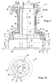
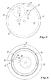
- Fig. 2 shows the internal structure of the winch with its gear 84 in conjunction with Figures 3 to 6, the individual Represent gear levels or levels.
- the winch base 12 is composed of two transmission boards 50 arranged one above the other, 51 formed, one to the outside and opposite the rest Winch interior closed and sealed, divided into two Form transmission space 40, which receives an oil bath, the ensures the lubrication of the gearbox.
- a winch support body is arranged above the boards the shape of a thin-walled tube with a cylindrical one Section 41, a slightly expanded room 43 for the third Gear stage and a flange 144 has. At the top free An inner flange is provided at the end, in the screws 45 protrude into the winch head 29 or end cover hold.
- Winch drum 14 mounted by means of needle bearings 46, namely in their upper and lower sections. This results in a very good power transmission with low material expenditure.
- a Plastic friction disc 48 takes the down on the winch drum acting tensile forces of the rope. Through the flange 43 of the support body 44 and the two transmission boards 50 and 51 reaching screws 49 are used to attach the winch on deck 13.
- the tubular cylindrical portion 41 of the support body 44 surrounds a likewise cylindrical engine compartment 47, which of the upper gear board 51 extends to the winch head 21.
- An electric geared motor 52 is arranged in this room. It has an elongated shape and is in the engine compartment 47 with motor axis 53 parallel to winch axis 28, somewhat off-center, arranged, on the top Flanged gearbox board 51.
- Motor 52 is a shunt DC motor the very high speeds up to idle 14,000 rpm reached by an internal planetary gear 54 to approx.4,000 rpm. belittles. Under pressure the speed goes down while increasing the torque. This is desirable because both when used as a drop as also Schotwinsch after initially getting through the lots eventual sealing fetch not go too fast should.
- the motor shaft 55 projects through the third gear stage 42 and the upper gear board 51 into the lower gear board 50 and is stored there and rotatably with one Drive pinion 56 connected to a gear 57 with considerably larger diameter engages (Fig. 3).
- the gear wheels are only dashed by their drawings drawn partial circles indicated.
- the gear 57 is seated rotatably on the shaft 58, which from the first gear level (Board 50) in the second gear level (board 51), the also forms the second gear stage, protrudes (Fig. 4). There it is rotatably connected to a pinion 59, which in turn drives a gear 60 with a larger diameter.
- the gear 60 has a toothing provided Outer rim 61 and a hub 62, which is rotatably connected to a shaft 63.
- a pawl freewheel is located between the outer ring 61 and the hub 62 64 provided.
- Three near the circumference of the hub arranged and protruding obliquely over their circumference
- Spring-loaded pawls 65 engage in reverse sawtooth Recesses 66 on the inner circumference of the outer ring 61 on.
- the shaft 63 protrudes through the upper board surface 67 of the Transmission board 51 sealed through and carries there rotatably a pinion 68 which drives an intermediate gear 69, the is mounted on a shaft 70. It engages in an internal ring gear 71 on the inner circumference of the winch drum and drives this on (Fig. 5).
- Fig. 6 shows that further on the inner circumference of the winch drum a sawtooth-like negative toothing 72 is provided in the pawls 73 engage the same type as before described. They are mounted on the support body 44 and form thus a pawl freewheel 75 for the winch drum, which locks them against reverse rotation.
- Pinion 76 In the first gear stage (Fig. 3) is also one of one Pinion 76 driven gear 77 mounted. Pinion 76 is non-rotatable with a drive shaft 98 for the mechanical Actuation provided via a square adapter 99th (Fig. 2) is connected to the winch crank nut 32. The wave 98 runs parallel, but eccentric to winch axis 28 through the engine compartment 47, close to the support body wall 41, so that sufficient in the engine compartment 47 There is still space for the engine.
- Gear 77 also includes a pawl freewheel 78 and is in the same way as the freewheel 64 from the outer ring 79, hub 80, pawls 81 and internal helical teeth 82 built up.
- the hub sits on shaft 70 and also drives the intermediate gear 69.
- the electrical connection of the winch is schematic in Fig. 9 shown: From an on-board battery 86, possibly via Main switches and fuses coming positive and negative Supply lines 87, 88 lead to a control unit 89, that in the plus line a contactor 90 and an overcurrent switch 91 contains.
- the relay 90 is, if necessary, via an auxiliary relay, controlled by a low-voltage circuit 92, in which there is an operating switch 93 for the winch.
- the Control device 89 can be arranged below deck in a suitable location and the operation switch 93 is preferred a robust and against moisture and possibly by a Pushbuttons protected against accidental actuation, which is mounted on deck near the winch.
- the winch works as follows: The rope 15 is in the Fig. 1 shown around the winch drum and is inserted into the gripping groove 23 via the guide lug. By Pulling the rope end 85 can pull the rope through for example, a sheet quickly after a turning maneuver to get through.
- the winch drum can move in the pulling direction 31 turn freely because the pawl freewheel 75 (Fig. 6) Freely runs in this direction without the gear would have to follow.
- the Operating switch 93 pressed. Via the control circuit 92 the contactor 90 is activated. This attracts and over the Overcurrent switch 91, the motor 52 is started. He drives the shaft 55 via the planetary gear 54 (FIG. 2) and thus in the first, lower gear stage 50 (FIG. 3) the pinion 56.
- the directions of rotation of the gear wheels in Fetch direction 31 are indicated by arrows.
- the first winch gear stage forms the shaft 58 and the pinion 59 in the second Gear stage (circuit board 51 in FIG. 4) becomes gear 60 driven. From the direction arrow (counterclockwise) can be seen that the freewheel 64 locks and accordingly the hub 62 and the shaft 63 taken become.
- the shaft 63 drives in the third gear stage (Fig. 5) the pinion 68 and thus the intermediate gear 69th so that the winch drum 14 in the pulling direction 31 (in Clockwise).
- the motor gear train does not need to be turned be, because with the engine stopped or turning slowly Freewheel 64 when driving the hub 62 counterclockwise the gear 60 is free running.
- Embodiment of the mother winch according to the invention makes it possible, also the motoring or crimping of the rope to make.
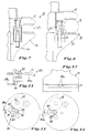
- the rocker switch 101 can be actuated by an actuating handle 104 in Intervention ( Figures 13, 17 and 21) or out of engagement ( Figures 14, 18 and 22) are brought with the intermediate gear 69, the drives the winch drum. So not only can Freewheel 78, but also the gear 79 are eliminated.
- a microswitch 105 is provided which in the control circuit and only when the mechanical is switched off Drive closes the control circuit and thus the electrical winch functions.
- the operating handle is formed as a spring plate 104a, which from the Winch base protrudes through a cutout 106a and between the positions shown in Figures 13 and 14 is pivotable. It snaps into the upper recesses under its spring force, the two end positions establish. The spring plate is pressed down to operate and can then be swiveled. One can on the spring plate Actuation button be put on.
- FIGS. 15 to 18 points for pivoting the rocker 101 a separate, teardrop-shaped Actuation lever 104b, which is about an axis 107 inside of a segment cutout 106b can be pivoted by approximately 180 ° is stored.
- a drive pin 108 runs in a fork groove 109 on the rocker 101 and pivots the rocker between the positions shown in Figures 17 and 18.
- the embodiment according to FIGS. 19 to 22 has an operating handle 104c in the form of an operating button, which in unactuated state (manual drive switched off) in is sunk into a segment-shaped cutout 106c (FIG. 22), but can be gripped and pulled out so that an inclined surface 110 on the operating handle 104 together with a pin on the rocker 101 to engage it Gear 69 releases.
- the tilting of the seesaw can be done can be effected by a spring 130.
- an additional contact force between the gears 103 and 69 manufactured by the on the gears acting reaction forces bring them together themselves.
- the motor winch with fiering device works with the following Procedure: The winch works under motor operation Get as previously described. If the winch is operated manually should be what is intended only in the fetch direction, is described above with reference to Figures 11 to 22 Switching mechanism 100 of the manual gear train switched on and by turning the winch handle clockwise Shaft 98, the pinion 102 and 103 and via the idler gear 69 the winch drum rotated. In this state it is Microswitch 105 open and therefore motor actuation locked out. Because of the freewheel 64, the motor will not turned.
- the return or bombing function is carried out by means of an electronic Sequence and control control via a logic module (Eprom) controlled.
- This is in a control device 112 integrated, which is shown schematically in Fig. 10 and itself located in the control unit 89.
- Eprom logic module
- a control device 112 integrated which is shown schematically in Fig. 10 and itself located in the control unit 89.
- an operation switch 113 for the Fierfunktion that belongs to the control circuit that already described microswitch 105 on the connection mechanism for the mechanical actuation and an electromechanical switch-off device for the winch drum freewheel 75. This consists, as indicated by dashed lines in Fig.
- the pawls 79 of the winch drum freewheel can bring back against their spring force and thus the Release winch drum 14 for rotation in both directions.
- the control 116 takes place via control lines 117.
- control unit 89 118 There is a braking resistor in or outside of control unit 89 118 provided, via a by the control device 112 controllable contactor or relay 119 the motor circuit closes.
- the motor is switched off again. Under the train of the The winch drum now begins in rope direction 39 to turn.
- the motor is driven and turns in Reverse direction of its normal direction of rotation until a preset Downwind speed is reached. This is about monitors the pulse generator 120 on the engine or in the gear train.
- relay 119 closed, so that now the resistor 118 from the as Generator acting motor is loaded and the motor is therefore acts as an engine brake.
- the winch drum turns with it a controlled speed braked backwards. Possibly could be through appropriate control or for example the choice of different resistances Reverse wind speed can be adjustable.
- the The retaining device 34 the rope 15 even with a reverse rotation in the gripping groove 23 of the self-retrieval device 22 to hold and prevent the rope end becomes free and the wrapping around the winch drum solves. So it is avoided that the rope tension in fierce suddenly collapses and is after the fiering process the rope is ready for retrieval.
- a winch is created by the invention that especially as a sheet or halyard winch for sailing yachts etc. suitable is. It has an integrated electrical or Hydraulic drive, whereby the motor is integrated into the winch is that he is inside the winch body and in particular lies within the winch drum. It causes an im Multi-stage gearbox on the winch base, supported possibly by a planetary gear present in the motor itself, the rotation of the winch drum.
- a manual Operation with winch handle is through a winch handle possible in the winch head, with the manual drive shaft on runs past the somewhat off-center motor.
- a reverse rotation or lubrication function can be provided the motor after switching off the drum lock braking and turning back at a controlled speed.
Landscapes
- Engineering & Computer Science (AREA)
- Mechanical Engineering (AREA)
- Chemical & Material Sciences (AREA)
- Combustion & Propulsion (AREA)
- Ocean & Marine Engineering (AREA)
- Soil Working Implements (AREA)
- Injection Moulding Of Plastics Or The Like (AREA)
- Transmission Devices (AREA)
- Cage And Drive Apparatuses For Elevators (AREA)
- Jib Cranes (AREA)
- Gear Transmission (AREA)
- Emergency Lowering Means (AREA)
Abstract
Description
- Fig. 1
- eine perspektivische Darstellung einer Winsch nach der Erfindung verbunden mit einem elek-trischen Schaltbild,
- Fig. 2
- einen schematischen Längsschnitt durch die Winsch,
- Fig. 3 bis 6
- schematische Querschnitte nach den Schnittlinien III-III-VI-VI in Fig. 2,
- Fig. 7 und 8
- durch ein Detail im Kreis VII-VIII in Fig. 2,
- Fig. 9 und 10
- elektrische Schaltbilder,
- Fig. 11 bis 14, 15 bis 18 und 19 bis 22
- jeweils drei Varianten einer Schaltmechanik für manuellen Betrieb und
- Fig. 23
- eine Draufsicht auf den Winschkopf.
Claims (15)
- Winsch für Seile (15), insbesondere für laufendes Gut, wie Fallen und Schoten auf Segelfahrzeugen, mit1.1 einer zumindest in einer Holrichtung (31) drehbaren Winschtrommel (14),1.2 einem an einem Basisteil (13) anbringbaren Winschsockel,1.3 einem Winschgetriebe (84),1.4 einem Motor (52), der zumindest teilweise in einem von der Winschtrommel (14) umgebenen Motorraum (47) angeordnet ist und über das Getriebe die Winschtrommel (14) antreibt.
- Winsch nach Anspruch 1, dadurch gekennzeichnet, dass der Motorraum (47) in einem im wesentlichen rohrförmigen Tragkörper (44) vorgesehen ist, auf dem die Winschtrommel (14) vorzugsweise mittels Nadellagern (46) drehbar gelagert ist, und dass der Motor (52) daran mit einer zur Drehachse (28) der Winschtrommel (14) paralleler Motorachse (53) montiert ist.
- Winsch nach Anspruch 1 oder 2, dadurch gekennzeichnet, dass sie einen zusätzlichen manuellen Antrieb aufweist, der vorzugsweise von einem die Winschtrommel (14) abdeckenden deckelartigen Winschkopf (29) aus über eine Winschkurbel betätigbar ist, wobei eine Antriebswelle (98) für den manuellen Antrieb an dem ggf. exzentrisch in dem Motorraum (47) angeordneten Motor (52) vorbei verläuft.
- Winsch nach einem der vorhergehenden Ansprüche, dadurch gekennzeichnet, dass sie das beim Holen von der Winschtrommel (14) ablaufende Seil (15) straffende Selbstholeinrichtung (22) aufweist, die nahe dem freien Ende der Winschtrommel (14) angeordnet ist und eine umlaufende Greifnut (23) aufweist, wobei vorzugsweise die Greifnut (23) zwei axial zur Winschtrommel (14) abstandsveränderliche Greifkörper (24, 25) aufweist, von denen insbesondere der eine als Flansch der Winschtrommel (14) und der andere als federnd axial bewegliche Ringscheibe (25) ausgebildet ist.
- Winsch nach einem der vorhergehenden Ansprüche, dadurch gekennzeichnet, dass der Motor als ein Elektro-Getriebemotor (52) mit integriertem, als Getriebevorstufe dienenden Motorgetriebe ausgebildet ist, das die Drehzahl des vorzugsweise als Gleichstrom-Nebenschlussmotor ausgebildeten Motors, der eine Leerlaufdrehzahl von über 10.000 U/Min., insbesondere bei ca. 14.000 U/Min., hat, vor der Einleitung in das Winschgetriebe (84) um das Drei- bis Fünffache verringert.
- Winsch nach einem der vorhergehenden Ansprüche, dadurch gekennzeichnet, dass das Winschgetriebe (84) und das Motorgetriebe (54) vorzugsweise als nichtselbsthemmende Stirnradgetriebe ausgebildet sind, wobei das Winschgetriebe (84) insbesondere in einem wartungsfreien Ölbad läuft.
- Winsch nach einem der vorhergehenden Ansprüche, dadurch gekennzeichnet, dass das Winschgetriebe (84) im Winschsockel (12) angeordnet ist und drei Getriebeebenen enthält, die jeweils eine Getriebestufe bilden, und wenigstens zwei scheibenartig übereinander gestapelte Platinen (50, 51) enthält, wobei ggf. die dritte Getriebestufe in einem die Winschtrommel (14) lagernden und von diesem umgebenen Tragkörper (44) gebildeten Raum enthalten ist.
- Winsch nach einem der vorhergehenden Ansprüche, dadurch gekennzeichnet, dass sie über eine elektrische, manuell einschaltbare Steuerung (89) betätigbar ist, die wenigstens ein Schütz (90) und eine Überstromsicherung (91) zur Begrenzung der maximalen Zugkraft aufweist.
- Winsch nach einem der Ansprüche 2 bis 8, dadurch gekennzeichnet, dass sie wenigstens zwei der folgenden Freiläufe aufweist:9.1 einen Winschtrommel-Freilauf (75), der ein Drehen der Winschtrommel (14) in Holrichtung (31) zuläßt, aber ein Rückdrehen entgegen der Holrichtung verhindert;9.2 einen ersten Getriebefreilauf (64), der den Getriebezug zwischen Motor und Getriebeanschluss des manuellen Antriebs eingeschaltet ist und den Motor (52) bei manuellem Betrieb abkuppelt;9.3 einen zweiten Getriebefreilauf (78), der im manuellen Antriebszug vorgesehen ist und diesen bei Motorbetrieb abkuppelt.
- Winsch nach einem der vorhergehenden Ansprüche, dadurch gekennzeichnet, dass sie eine Fiereinrichtung mit einer elektrischen Steuereinrichtung (112) enthält, mit der ein unter Zug stehendes Seil (15) gelockert bzw. nachgelassen werden kann, wobei der Motor (52) als ggf. geregelte Bremse eingesetzt ist.
- Winsch nach einem der vorhergehenden Ansprüche, dadurch gekennzeichnet, dass ein manueller Antrieb der Winsch beim Motorbetrieb abgeschaltet und bei manueller Betätigung über einen manuell betätigbaren Zuschaltmechanismus (100) zuschaltbar ist.
- Winsch nach Anspruch 10 oder 11, dadurch gekennzeichnet, dass der Winschtrommelfreilauf (75) durch die Steuereinrichtung (112) mittels elektrischer Betätigung freischaltbar ist, so dass die Winschtrommel (14) in beide Drehrichtungen drehbar ist, wobei die Freischaltung insbesondere durch eine elektromagnetische oder elektromechanische Abhebung von Sperrklinken (73) eines den Freilauf (75) bildenden Klinkengesperres erfolgt und wobei ggf. die Freischaltung nach einer motorischen Betätigung in Holrichtung (31) zum Lösen der Sperrklinken (73) erfolgt.
- Winsch nach Anspruch 12, dadurch gekennzeichnet, dass der Motor (52) von der unter dem Zug des Seils (15) rückgedrehten Winschtrommel (14) rückdrehbar ist und die Steuereinrichtung (112) einen Bremswiderstand (118) enthält, der von der Steuereinrichtung (112) bei einer vorgegebenen Rückdrehzahl zugeschaltet wird, und die Steuereinrichtung ggf. nach manuellem Abschalten der Fiereinrichtung den Motor in Holrichtung (31) ansteuert, bis die Winschtrommel (14) nahezu Stillstand erreicht hat, wonach sie den Freilauf (75) wieder zuschaltet.
- Winsch nach einem der vorhergehenden Ansprüche, dadurch gekennzeichnet, dass die Selbstholeinrichtung (22) eine Rückhalteeinrichtung (34) enthält, die das Seil (15) auch beim Fieren in der Selbstholeinrichtung hält und vorzugsweise einen federnden Rückhaltehebel (35) aufweist, der in Seillaufrichtung in Umfangsabstand von einer Leiteinrichtung (30), die das Seil von der Winschtrommel in die Selbstholeinrichtung (22) leitet, angeordnet ist.
- Winsch nach einem der vorhergehenden Ansprüche, dadurch gekennzeichnet, dass die Winschtrommel (14) an ihrer als Kontaktfläche zum Seil dienenden Außenfläche (16) jeweils in Umfangsabstand voneinander Gruppen von vorzugsweise zwei etwa achsparallelen Rippen (17) aufweist.
Priority Applications (5)
| Application Number | Priority Date | Filing Date | Title |
|---|---|---|---|
| DE20000724U DE20000724U1 (de) | 2000-01-18 | 2000-01-18 | Motorwinsch |
| CA002331145A CA2331145C (en) | 2000-01-18 | 2001-01-16 | Winch |
| NZ509426A NZ509426A (en) | 2000-01-18 | 2001-01-17 | Winch with motor totally enclosed within drum |
| AU16345/01A AU778332B2 (en) | 2000-01-18 | 2001-01-18 | Winch |
| US09/765,071 US6431103B1 (en) | 2000-01-18 | 2001-01-18 | Winch |
Applications Claiming Priority (2)
| Application Number | Priority Date | Filing Date | Title |
|---|---|---|---|
| DE20000724U | 2000-01-18 | ||
| DE20000724U DE20000724U1 (de) | 2000-01-18 | 2000-01-18 | Motorwinsch |
Publications (3)
| Publication Number | Publication Date |
|---|---|
| EP1125885A2 true EP1125885A2 (de) | 2001-08-22 |
| EP1125885A3 EP1125885A3 (de) | 2002-04-10 |
| EP1125885B1 EP1125885B1 (de) | 2006-03-01 |
Family
ID=7935990
Family Applications (1)
| Application Number | Title | Priority Date | Filing Date |
|---|---|---|---|
| EP00710043A Expired - Lifetime EP1125885B1 (de) | 2000-01-18 | 2000-12-18 | Winsch |
Country Status (3)
| Country | Link |
|---|---|
| EP (1) | EP1125885B1 (de) |
| AT (1) | ATE318786T1 (de) |
| DE (1) | DE50012307D1 (de) |
Cited By (8)
| Publication number | Priority date | Publication date | Assignee | Title |
|---|---|---|---|---|
| EP1362822A3 (de) * | 2002-05-17 | 2005-06-15 | Domenico Manca | Umwandelbare Winde |
| GB2496446A (en) * | 2011-11-11 | 2013-05-15 | Lewmar Ltd | Self-tailing winch |
| DE202012007843U1 (de) * | 2012-08-17 | 2013-11-19 | Duallift Gmbh | Seildurchlaufwinde mit Freilauf |
| US8820720B2 (en) | 2011-11-11 | 2014-09-02 | Lewmar Limited | Winch |
| WO2018041722A1 (fr) * | 2016-09-02 | 2018-03-08 | Pontos | Cabestan à assistance motorisée |
| CN110775849A (zh) * | 2019-11-07 | 2020-02-11 | 浙江润华机电有限公司 | 一种绞盘 |
| EP3753468B1 (de) | 2016-03-31 | 2022-01-19 | MEIKO Maschinenbau GmbH & Co. KG | Reinigungsvorrichtung und verfahren zum reinigen von reinigungsgut |
| US12013023B2 (en) | 2020-05-06 | 2024-06-18 | Liebherr-Components Biberach Gmbh | Drive unit for a construction and/or material handling machine |
Families Citing this family (1)
| Publication number | Priority date | Publication date | Assignee | Title |
|---|---|---|---|---|
| SE535253C2 (sv) | 2010-10-15 | 2012-06-05 | Selden Mast Ab | Sätt och anordning vid linvinsch till segelbåt |
Family Cites Families (7)
| Publication number | Priority date | Publication date | Assignee | Title |
|---|---|---|---|---|
| DE425951C (de) * | 1924-02-23 | 1926-02-26 | Otto Steltzner | Spill mit eingebautem Elektromotor |
| FR767178A (fr) * | 1933-01-21 | 1934-07-12 | Theodor Bell & Cie Ag | Cabestan électrique |
| US2826939A (en) * | 1954-08-02 | 1958-03-18 | Otto E Dever | Capstan |
| US3968953A (en) * | 1975-01-27 | 1976-07-13 | Barient Company | Self-tailing winch |
| DE2505053A1 (de) * | 1975-02-06 | 1976-08-19 | Klaus Peter Flamme | Anordnung zum antreiben von wenigstens einer seilwinde auf einem segelboot |
| US4084793A (en) * | 1976-05-19 | 1978-04-18 | Byrd Industries, Inc. | Winch with automatic clutch assembly |
| US5927691A (en) * | 1994-06-07 | 1999-07-27 | Harken, Inc. | Four speed sailboat winch having separate second gear |
-
2000
- 2000-12-18 AT AT00710043T patent/ATE318786T1/de not_active IP Right Cessation
- 2000-12-18 DE DE50012307T patent/DE50012307D1/de not_active Expired - Fee Related
- 2000-12-18 EP EP00710043A patent/EP1125885B1/de not_active Expired - Lifetime
Cited By (12)
| Publication number | Priority date | Publication date | Assignee | Title |
|---|---|---|---|---|
| EP1362822A3 (de) * | 2002-05-17 | 2005-06-15 | Domenico Manca | Umwandelbare Winde |
| GB2496446A (en) * | 2011-11-11 | 2013-05-15 | Lewmar Ltd | Self-tailing winch |
| US8820720B2 (en) | 2011-11-11 | 2014-09-02 | Lewmar Limited | Winch |
| GB2496446B (en) * | 2011-11-11 | 2014-12-31 | Lewmar Ltd | Winch |
| US9061870B2 (en) | 2011-11-11 | 2015-06-23 | Lewmar Limited | Winch |
| DE202012007843U1 (de) * | 2012-08-17 | 2013-11-19 | Duallift Gmbh | Seildurchlaufwinde mit Freilauf |
| EP3753468B1 (de) | 2016-03-31 | 2022-01-19 | MEIKO Maschinenbau GmbH & Co. KG | Reinigungsvorrichtung und verfahren zum reinigen von reinigungsgut |
| WO2018041722A1 (fr) * | 2016-09-02 | 2018-03-08 | Pontos | Cabestan à assistance motorisée |
| FR3055619A1 (fr) * | 2016-09-02 | 2018-03-09 | Pontos | Cabestan a assistance motorisee |
| CN110775849A (zh) * | 2019-11-07 | 2020-02-11 | 浙江润华机电有限公司 | 一种绞盘 |
| CN110775849B (zh) * | 2019-11-07 | 2020-11-13 | 浙江润华机电有限公司 | 一种绞盘 |
| US12013023B2 (en) | 2020-05-06 | 2024-06-18 | Liebherr-Components Biberach Gmbh | Drive unit for a construction and/or material handling machine |
Also Published As
| Publication number | Publication date |
|---|---|
| EP1125885A3 (de) | 2002-04-10 |
| DE50012307D1 (de) | 2006-04-27 |
| EP1125885B1 (de) | 2006-03-01 |
| ATE318786T1 (de) | 2006-03-15 |
Similar Documents
| Publication | Publication Date | Title |
|---|---|---|
| DE2709089C2 (de) | Winde für Kran, insbesondere Schiffskran | |
| DE68910732T2 (de) | Betätigungseinrichtung für automatische Getriebe. | |
| DE19531043C2 (de) | Planetengetriebesystem | |
| EP0990614B1 (de) | Notbefreiungseinrichtung | |
| DE1481902A1 (de) | Windengestell | |
| DE2019701A1 (de) | Motorwinde fuer Arbeitsplattformen | |
| DE2618543C3 (de) | Vorrichtung zum Ver- und Entriegeln eines Drehkreuzes | |
| EP1125885A2 (de) | Ankerwinde | |
| DE102016116692B4 (de) | Vorrichtung zum Betätigen einer Parksperre in einem Automatik-Getriebe eines Kraftfahrzeuges | |
| DE3113362A1 (de) | Einrichtung zur betaetigung einer kraftfahrzeug-feststellbremse | |
| DE1506484B1 (de) | Notschaltung fuer einen Aufzug | |
| DE10008451A1 (de) | Schubkarren mit einem elektrischen Antrieb zur Schubkraftunterstützung | |
| EP0139264A1 (de) | Vorrichtung zum Rückdrehen der Einzugsschnecke eines Mähdreschers | |
| DE3446657A1 (de) | Hilfsantrieb fuer aufzuege | |
| EP1107909A1 (de) | Schiffsgetriebe | |
| EP0947460A1 (de) | Notbefreiungseinrichtung | |
| DE918476C (de) | Angelwinde mit Mehrganggetriebe | |
| DE3309670A1 (de) | Hebelhebezeug | |
| DE1756047A1 (de) | Elektrisch angetriebene,selbststeuernde Seilwinde,insbesondere fuer Schiffe | |
| DE2400987A1 (de) | Hubwerk mit motorantrieb fuer ein bewegliches teil, insbesondere fuer ein tor | |
| DE69509654T2 (de) | Motorangetriebene winde,zur verankerung von schiffen | |
| DE1957606A1 (de) | Winde fuer Schiffsanker | |
| DE684829C (de) | Hubgetriebe fuer Hebezeuge | |
| DE1214849B (de) | Seilwinde zum Verladen von Baumstaemmen auf Fahrzeuge | |
| DE102011078049B3 (de) | Spannvorrichtung |
Legal Events
| Date | Code | Title | Description |
|---|---|---|---|
| PUAI | Public reference made under article 153(3) epc to a published international application that has entered the european phase |
Free format text: ORIGINAL CODE: 0009012 |
|
| AK | Designated contracting states |
Kind code of ref document: A2 Designated state(s): AT BE CH CY DE DK ES FI FR GB GR IE IT LI LU MC NL PT SE TR |
|
| AX | Request for extension of the european patent |
Free format text: AL;LT;LV;MK;RO;SI |
|
| PUAL | Search report despatched |
Free format text: ORIGINAL CODE: 0009013 |
|
| AK | Designated contracting states |
Kind code of ref document: A3 Designated state(s): AT BE CH CY DE DK ES FI FR GB GR IE IT LI LU MC NL PT SE TR |
|
| AX | Request for extension of the european patent |
Free format text: AL;LT;LV;MK;RO;SI |
|
| RIC1 | Information provided on ipc code assigned before grant |
Free format text: 7B 66D 1/74 A, 7B 63B 21/16 B |
|
| 17P | Request for examination filed |
Effective date: 20020920 |
|
| AKX | Designation fees paid |
Free format text: AT BE CH CY DE DK ES FI FR GB GR IE IT LI LU MC NL PT SE TR |
|
| 17Q | First examination report despatched |
Effective date: 20041118 |
|
| GRAP | Despatch of communication of intention to grant a patent |
Free format text: ORIGINAL CODE: EPIDOSNIGR1 |
|
| RTI1 | Title (correction) |
Free format text: CAPSTAN |
|
| GRAS | Grant fee paid |
Free format text: ORIGINAL CODE: EPIDOSNIGR3 |
|
| GRAA | (expected) grant |
Free format text: ORIGINAL CODE: 0009210 |
|
| AK | Designated contracting states |
Kind code of ref document: B1 Designated state(s): AT BE CH CY DE DK ES FI FR GB GR IE IT LI LU MC NL PT SE TR |
|
| PG25 | Lapsed in a contracting state [announced via postgrant information from national office to epo] |
Ref country code: FI Free format text: LAPSE BECAUSE OF FAILURE TO SUBMIT A TRANSLATION OF THE DESCRIPTION OR TO PAY THE FEE WITHIN THE PRESCRIBED TIME-LIMIT Effective date: 20060301 Ref country code: NL Free format text: LAPSE BECAUSE OF FAILURE TO SUBMIT A TRANSLATION OF THE DESCRIPTION OR TO PAY THE FEE WITHIN THE PRESCRIBED TIME-LIMIT Effective date: 20060301 Ref country code: IE Free format text: LAPSE BECAUSE OF FAILURE TO SUBMIT A TRANSLATION OF THE DESCRIPTION OR TO PAY THE FEE WITHIN THE PRESCRIBED TIME-LIMIT Effective date: 20060301 Ref country code: IT Free format text: LAPSE BECAUSE OF FAILURE TO SUBMIT A TRANSLATION OF THE DESCRIPTION OR TO PAY THE FEE WITHIN THE PRE;WARNING: LAPSES OF ITALIAN PATENTS WITH EFFECTIVE DATE BEFORE 2007 MAY HAVE OCCURRED AT ANY TIME BEFORE 2007. THE CORRECT EFFECTIVE DATE MAY BE DIFFERENT FROM THE ONE RECORDED.SCRIBED TIME-LIMIT Effective date: 20060301 |
|
| REG | Reference to a national code |
Ref country code: GB Ref legal event code: FG4D Free format text: NOT ENGLISH |
|
| REG | Reference to a national code |
Ref country code: CH Ref legal event code: EP |
|
| REG | Reference to a national code |
Ref country code: IE Ref legal event code: FG4D Free format text: LANGUAGE OF EP DOCUMENT: GERMAN |
|
| REF | Corresponds to: |
Ref document number: 50012307 Country of ref document: DE Date of ref document: 20060427 Kind code of ref document: P |
|
| PG25 | Lapsed in a contracting state [announced via postgrant information from national office to epo] |
Ref country code: SE Free format text: LAPSE BECAUSE OF FAILURE TO SUBMIT A TRANSLATION OF THE DESCRIPTION OR TO PAY THE FEE WITHIN THE PRESCRIBED TIME-LIMIT Effective date: 20060601 Ref country code: DK Free format text: LAPSE BECAUSE OF FAILURE TO SUBMIT A TRANSLATION OF THE DESCRIPTION OR TO PAY THE FEE WITHIN THE PRESCRIBED TIME-LIMIT Effective date: 20060601 |
|
| PG25 | Lapsed in a contracting state [announced via postgrant information from national office to epo] |
Ref country code: ES Free format text: LAPSE BECAUSE OF FAILURE TO SUBMIT A TRANSLATION OF THE DESCRIPTION OR TO PAY THE FEE WITHIN THE PRESCRIBED TIME-LIMIT Effective date: 20060612 |
|
| GBT | Gb: translation of ep patent filed (gb section 77(6)(a)/1977) |
Effective date: 20060619 |
|
| PG25 | Lapsed in a contracting state [announced via postgrant information from national office to epo] |
Ref country code: PT Free format text: LAPSE BECAUSE OF FAILURE TO SUBMIT A TRANSLATION OF THE DESCRIPTION OR TO PAY THE FEE WITHIN THE PRESCRIBED TIME-LIMIT Effective date: 20060801 |
|
| NLV1 | Nl: lapsed or annulled due to failure to fulfill the requirements of art. 29p and 29m of the patents act | ||
| REG | Reference to a national code |
Ref country code: IE Ref legal event code: FD4D |
|
| PG25 | Lapsed in a contracting state [announced via postgrant information from national office to epo] |
Ref country code: MC Free format text: LAPSE BECAUSE OF NON-PAYMENT OF DUE FEES Effective date: 20061231 Ref country code: BE Free format text: LAPSE BECAUSE OF NON-PAYMENT OF DUE FEES Effective date: 20061231 Ref country code: LI Free format text: LAPSE BECAUSE OF NON-PAYMENT OF DUE FEES Effective date: 20061231 Ref country code: CH Free format text: LAPSE BECAUSE OF NON-PAYMENT OF DUE FEES Effective date: 20061231 |
|
| PLBE | No opposition filed within time limit |
Free format text: ORIGINAL CODE: 0009261 |
|
| STAA | Information on the status of an ep patent application or granted ep patent |
Free format text: STATUS: NO OPPOSITION FILED WITHIN TIME LIMIT |
|
| 26N | No opposition filed |
Effective date: 20061204 |
|
| EN | Fr: translation not filed | ||
| PG25 | Lapsed in a contracting state [announced via postgrant information from national office to epo] |
Ref country code: DE Free format text: LAPSE BECAUSE OF NON-PAYMENT OF DUE FEES Effective date: 20070703 |
|
| REG | Reference to a national code |
Ref country code: CH Ref legal event code: PL |
|
| BERE | Be: lapsed |
Owner name: MEYERDIERKS, HELMUT Effective date: 20061231 |
|
| PG25 | Lapsed in a contracting state [announced via postgrant information from national office to epo] |
Ref country code: AT Free format text: LAPSE BECAUSE OF NON-PAYMENT OF DUE FEES Effective date: 20061218 |
|
| PG25 | Lapsed in a contracting state [announced via postgrant information from national office to epo] |
Ref country code: GR Free format text: LAPSE BECAUSE OF FAILURE TO SUBMIT A TRANSLATION OF THE DESCRIPTION OR TO PAY THE FEE WITHIN THE PRESCRIBED TIME-LIMIT Effective date: 20060602 |
|
| PG25 | Lapsed in a contracting state [announced via postgrant information from national office to epo] |
Ref country code: LU Free format text: LAPSE BECAUSE OF NON-PAYMENT OF DUE FEES Effective date: 20061218 Ref country code: TR Free format text: LAPSE BECAUSE OF FAILURE TO SUBMIT A TRANSLATION OF THE DESCRIPTION OR TO PAY THE FEE WITHIN THE PRESCRIBED TIME-LIMIT Effective date: 20060301 |
|
| PG25 | Lapsed in a contracting state [announced via postgrant information from national office to epo] |
Ref country code: CY Free format text: LAPSE BECAUSE OF FAILURE TO SUBMIT A TRANSLATION OF THE DESCRIPTION OR TO PAY THE FEE WITHIN THE PRESCRIBED TIME-LIMIT Effective date: 20060301 Ref country code: FR Free format text: LAPSE BECAUSE OF FAILURE TO SUBMIT A TRANSLATION OF THE DESCRIPTION OR TO PAY THE FEE WITHIN THE PRESCRIBED TIME-LIMIT Effective date: 20060301 |
|
| PGFP | Annual fee paid to national office [announced via postgrant information from national office to epo] |
Ref country code: GB Payment date: 20141216 Year of fee payment: 15 |
|
| GBPC | Gb: european patent ceased through non-payment of renewal fee |
Effective date: 20151218 |
|
| PG25 | Lapsed in a contracting state [announced via postgrant information from national office to epo] |
Ref country code: GB Free format text: LAPSE BECAUSE OF NON-PAYMENT OF DUE FEES Effective date: 20151218 |