EP1126095A2 - Vorgefertigte Betonplatte zum Herstellen von Decken in Zivil- oder Industriebau - Google Patents
Vorgefertigte Betonplatte zum Herstellen von Decken in Zivil- oder Industriebau Download PDFInfo
- Publication number
- EP1126095A2 EP1126095A2 EP00128117A EP00128117A EP1126095A2 EP 1126095 A2 EP1126095 A2 EP 1126095A2 EP 00128117 A EP00128117 A EP 00128117A EP 00128117 A EP00128117 A EP 00128117A EP 1126095 A2 EP1126095 A2 EP 1126095A2
- Authority
- EP
- European Patent Office
- Prior art keywords
- panel
- panel according
- sheet
- floor
- faces
- Prior art date
- Legal status (The legal status is an assumption and is not a legal conclusion. Google has not performed a legal analysis and makes no representation as to the accuracy of the status listed.)
- Granted
Links
- 239000004567 concrete Substances 0.000 title claims abstract description 25
- 238000009423 ventilation Methods 0.000 claims abstract description 34
- 230000002787 reinforcement Effects 0.000 claims abstract description 21
- 238000005266 casting Methods 0.000 claims abstract description 15
- 239000011810 insulating material Substances 0.000 claims abstract description 5
- 238000004873 anchoring Methods 0.000 claims description 9
- 230000001681 protective effect Effects 0.000 claims description 4
- 238000009413 insulation Methods 0.000 description 10
- 230000005494 condensation Effects 0.000 description 5
- 238000009833 condensation Methods 0.000 description 5
- 229920006248 expandable polystyrene Polymers 0.000 description 5
- 230000015572 biosynthetic process Effects 0.000 description 4
- 238000010276 construction Methods 0.000 description 4
- 238000009434 installation Methods 0.000 description 4
- 238000004519 manufacturing process Methods 0.000 description 4
- 239000004793 Polystyrene Substances 0.000 description 3
- 229920002223 polystyrene Polymers 0.000 description 3
- 239000011150 reinforced concrete Substances 0.000 description 2
- 241001465754 Metazoa Species 0.000 description 1
- XAGFODPZIPBFFR-UHFFFAOYSA-N aluminium Chemical compound [Al] XAGFODPZIPBFFR-UHFFFAOYSA-N 0.000 description 1
- 229910052782 aluminium Inorganic materials 0.000 description 1
- 230000002860 competitive effect Effects 0.000 description 1
- 230000000694 effects Effects 0.000 description 1
- 230000008030 elimination Effects 0.000 description 1
- 238000003379 elimination reaction Methods 0.000 description 1
- 239000003517 fume Substances 0.000 description 1
- 230000000670 limiting effect Effects 0.000 description 1
- 239000000463 material Substances 0.000 description 1
- 230000013011 mating Effects 0.000 description 1
- 238000012986 modification Methods 0.000 description 1
- 230000004048 modification Effects 0.000 description 1
- 238000013021 overheating Methods 0.000 description 1
- 238000004381 surface treatment Methods 0.000 description 1
Images


Classifications
-
- E—FIXED CONSTRUCTIONS
- E04—BUILDING
- E04B—GENERAL BUILDING CONSTRUCTIONS; WALLS, e.g. PARTITIONS; ROOFS; FLOORS; CEILINGS; INSULATION OR OTHER PROTECTION OF BUILDINGS
- E04B5/00—Floors; Floor construction with regard to insulation; Connections specially adapted therefor
- E04B5/48—Special adaptations of floors for incorporating ducts, e.g. for heating or ventilating
-
- E—FIXED CONSTRUCTIONS
- E04—BUILDING
- E04B—GENERAL BUILDING CONSTRUCTIONS; WALLS, e.g. PARTITIONS; ROOFS; FLOORS; CEILINGS; INSULATION OR OTHER PROTECTION OF BUILDINGS
- E04B5/00—Floors; Floor construction with regard to insulation; Connections specially adapted therefor
- E04B5/02—Load-carrying floor structures formed substantially of prefabricated units
- E04B5/04—Load-carrying floor structures formed substantially of prefabricated units with beams or slabs of concrete or other stone-like material, e.g. asbestos cement
-
- E—FIXED CONSTRUCTIONS
- E04—BUILDING
- E04G—SCAFFOLDING; FORMS; SHUTTERING; BUILDING IMPLEMENTS OR AIDS, OR THEIR USE; HANDLING BUILDING MATERIALS ON THE SITE; REPAIRING, BREAKING-UP OR OTHER WORK ON EXISTING BUILDINGS
- E04G21/00—Preparing, conveying, or working-up building materials or building elements in situ; Other devices or measures for constructional work
- E04G21/14—Conveying or assembling building elements
- E04G21/142—Means in or on the elements for connecting same to handling apparatus
- E04G21/145—Means in or on the elements for connecting same to handling apparatus specific for hollow plates
-
- E—FIXED CONSTRUCTIONS
- E04—BUILDING
- E04G—SCAFFOLDING; FORMS; SHUTTERING; BUILDING IMPLEMENTS OR AIDS, OR THEIR USE; HANDLING BUILDING MATERIALS ON THE SITE; REPAIRING, BREAKING-UP OR OTHER WORK ON EXISTING BUILDINGS
- E04G21/00—Preparing, conveying, or working-up building materials or building elements in situ; Other devices or measures for constructional work
- E04G21/32—Safety or protective measures for persons during the construction of buildings
- E04G21/3261—Safety-nets; Safety mattresses; Arrangements on buildings for connecting safety-lines
- E04G21/3276—Arrangements on buildings for connecting safety-lines
-
- E—FIXED CONSTRUCTIONS
- E04—BUILDING
- E04G—SCAFFOLDING; FORMS; SHUTTERING; BUILDING IMPLEMENTS OR AIDS, OR THEIR USE; HANDLING BUILDING MATERIALS ON THE SITE; REPAIRING, BREAKING-UP OR OTHER WORK ON EXISTING BUILDINGS
- E04G21/00—Preparing, conveying, or working-up building materials or building elements in situ; Other devices or measures for constructional work
- E04G21/32—Safety or protective measures for persons during the construction of buildings
- E04G21/3204—Safety or protective measures for persons during the construction of buildings against falling down
- E04G2021/3257—Safety or protective measures for persons during the construction of buildings against falling down specific for floors made of prefabricated hollow plates
Definitions
- the present invention relates to a prefabricated concrete panel for building floors in civil or industrial structures.
- Prefabricated reinforced-concrete components for building floors are divided into two categories: components for forming ribbed floors, i.e., with ribs on the intrados or underside of the floor, and components for forming flat floors, i.e., with a flat intrados.
- Prefabricated components for forming ribbed floors generally have a transverse cross-section which is substantially T-shaped or derives from the mating of two or three T-shapes, depending on whether they have two or three ribbing wings on the intrados.
- Prefabricated components for building flat floors can in turn be divided into three categories: honeycomb components, concrete panels with a thermal insulation layer, and panels with contoured sheets of extruded polystyrene which act as a thermal insulation and provide internal ventilation of the components.
- Honeycomb components are constituted by prestressed reinforced concrete panels with reinforcements which lie exclusively longitudinally and with a plurality of uniform longitudinal passages which are not connected one another and are designed to ventilate the inside of the panels, reducing the formation of condensation.
- Concrete panels with a thermal insulation layer are generally constituted by a concrete body which embeds a flat sheet of foamed polystyrene being interposed between the two main faces of the panel. These panels suffer the drawback that they do not effectively oppose the formation of condensation, since they do not have an internal ventilation system.
- Concrete panels with contoured sheets of extruded polystyrene are generally constituted by a concrete body having, on its face meant to be covered by the casting of the topping, contoured sheets of foamed polystyrene which form a plurality of longitudinally elongated ventilation channels which are not mutually connected.
- the reinforcement can only be constituted by longitudinal rods in order to avoid interrupting the polystyrene which provides the ventilation channels.
- the aim of the present invention is to solve the above-noted problems, by providing a prefabricated concrete panel for building floors in civil or industrial structures which allows to obtain, for the floor, a high thermal and/or acoustic insulation and effectively avoids the formation of condensation inside it.
- an object of the invention is to provide a prefabricated panel which is self-supporting and walkable immediately after its installation.
- Another object of the invention is to provide a prefabricated panel which has high mechanical strength without requiring prestressing and is therefore particularly simple and rapid to manufacture.
- Another object of the invention is to provide a prefabricated panel which also achieves excellent anchoring of the casting of the topping.
- Another object of the invention is to provide a panel which allows to produce floors in extremely short times without requiring the use of propping.
- Another object of the invention is to provide a prefabricated panel which can be manufactured at competitive costs.
- a prefabricated concrete panel for building floors in civil or industrial structures characterized in that it comprises a concrete body with a reinforcement provided with portions which protrude from one of two larger faces of the body of the panel which constitutes extrados of a floor and are designed to be embedded in a casting of a topping of the floor, at least one first contoured sheet being provided inside the body of the panel, said sheet being made of thermally insulating material, being interposed between the two larger faces of the panel body and forming, between said two larger faces of the panel body, a ventilation chamber which is composed of a plurality of mutually connected cells.
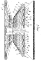
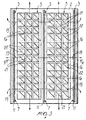
- the prefabricated panel according to the invention comprises a concrete body 2 with a reinforcement 3 provided with portions which protrude from one of the larger faces of the panel body that constitutes the extrados of the floor and are meant to be embedded in the casting of the topping 4 of the floor.
- At least one contoured sheet 5 made of thermally insulating material, preferably foamed polystyrene, which is interposed between the two larger faces of the panel body 2 and forms, between said two larger faces of the panel body 2, a ventilation chamber 6 which is composed of a plurality of mutually connected cells.
- the reinforcement 3 comprises longitudinal profiles 7 which are arranged on a plane which is substantially parallel to the two larger faces of the panel body and are orientated parallel to the larger sides of the panel. Substantially, the longitudinal profiles 7 are orientated at right angles to the two opposite sides of the panel that are meant to be rested on two beams 35 for supporting the floor.
- the reinforcement can be constituted exclusively by longitudinal profiles 7, as shown, or can also comprise transverse profiles, not shown for the sake of simplicity, which mutually connect the longitudinal profiles 7.
- the reinforcement of the panel is constituted by a frame-like structure.
- the profiles 7 of the reinforcement of the panel according to the invention have a substantially C- or ⁇ -shaped transverse cross-section, with two end wings 11 and 12 which are arranged on planes which are parallel to each other and to the larger faces of the panel.
- the two end wings 11 and 12 are mutually connected by an intermediate wing 13.
- One of the end wings in the illustrated case the end wing 11, and a portion of the intermediate wing 13, starting from said end wing 11, protrude from the larger face of the panel body 2 that constitutes the extrados of the floor and are meant to be embedded in the casting of the topping 4.
- the profiles 7 of the reinforcement 3 can have, along their extension, perforations and/or undulations in order to increase the anchoring of said profiles 7 in the concrete body 2 of the panel.
- the panel according to the invention comprises a second sheet 15, preferably made of thermally insulating material, such as for example foamed polystyrene, which is substantially flat and faces the first sheet 5.
- the first sheet 5 and the second sheet 15 are arranged on planes which are parallel to the planes of arrangement of the two larger faces of the panel body, and said sheets delimit between them the ventilation chamber 6.
- the first sheet 5 is shaped so as to form cups 16 which are arranged mutually side by side and form concave recesses 17 of the face of the first sheet 5 that faces the second sheet 15.
- the side of said recesses 17 that is directed toward the second sheet 15 is closed by the second sheet 15.
- the recesses 17, which constitute the cells into which the ventilation chamber 6 is divided, are mutually connected by means of connecting ducts which have smaller air passage sections than the recesses 17.
- the connecting ducts are constituted by passages 18 formed in the edges of the cups 16 that are directed toward the second sheet 15.
- the recesses 17 are further connected to at least one ventilation duct 19 which leads onto one of the outer sides of the panel.
- Protective grilles 20 are conveniently arranged on the outlets of the ventilation ducts 19 and are meant to prevent the intrusion, inside the panel, of animals or dirt and can be actuated in order to adjust the flow of air in the ventilation chamber 6.
- the protective grilles 20 can further be provided with mechanical or manual means for adjusting their opening.
- the cups 16 are delimited, on the face of the first sheet 5 that lies opposite the second sheet 15, by grooves 21 which are recessed with respect to the back of the cups, which instead protrudes from the face of the first sheet 5 that is directed away from the second sheet 15.
- the ribs 22 preferably run diagonally with respect to the larger faces of the panel. More particularly, the cups 16 have a substantially rectangular base and the ribs 22 lie along a diagonal of the rectangular shape of the back of the cups 16.
- the ribs 22 are designed to support an auxiliary reinforcement if it is provided; the auxiliary reinforcement is constituted by a net or by bars, which the ribs support so as to keep them correctly spaced from the remaining part of the first sheet 5, so as to obtain an excellent anchoring of the auxiliary reinforcement inside the concrete layer that covers the side of the first sheet 5 that lies opposite with respect to the second sheet 15.
- An auxiliary reinforcement constituted by a net or by bars, can also be provided in the layer of concrete that covers the side of the second sheet 15 that lies opposite with respect to the first sheet 5, in order to further increase the mechanical strength of the panel.
- the first sheet 5 and the second sheet 15 are made of foamed polystyrene, and in order to further increase the thermal insulation effect of these sheets their mutually facing faces can be covered with a reflective layer which can be constituted by a thin aluminum layer or synthetic layer, in any case a reflective one, which is applied to the mutually facing faces of the sheets 5 and 15.
- a reflective layer which can be constituted by a thin aluminum layer or synthetic layer, in any case a reflective one, which is applied to the mutually facing faces of the sheets 5 and 15.
- the body 2 of the panel has recesses 30 on at least two of its smaller faces which are arranged on mutually opposite sides and which, in the floor, are meant to face contiguous panels; the recesses form undercuts for the anchoring of the concrete that constitutes the casting of the topping 4.
- the recesses 30 obtain, for the casting of the topping 4, a plurality of ribs which in addition to increasing the anchoring of the casting of the topping 4 to the set of panels according to the invention that constitutes the floor, also increase the mechanical strength of the casting of the topping 4.
- the larger face of the panel body 2 that constitutes the intrados of the floor is perfectly flat and can optionally be pre-finished with all the variations of surface treatment for panels for prefabricated building faces, for example bushhammered, sanded, on a pattern, with exposed stones, et cetera, depending on the requirements, or simply painted.
- the body 2 of the panel can further have, according to requirements, through cutouts in order to provide openings in the floor.
- inserts 31 which form grip regions for the lifting or movement of the panel.
- inserts 31 can be constituted by plates, for example if the lifting device is of the type disclosed in EP-0568.934 by the same Applicants, or by tubular bodies, for example if the lifting device is of the type disclosed in EPA-97116788.7 by the same Applicants.
- inserts as well as optionally other inserts, can be used, as shown in particular in Figure 6, as anchoring points for safety cables or harnesses in order to anchor the operators to the panel during the construction of the floor.
- two opposite sides of the panel that are meant to be rested on the supporting beams 35 of the floor can be provided flat or with steps.
- Construction of a floor by means of panels according to the invention is as follows.
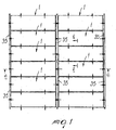
- the panels according to the invention are rested, with their two opposite transverse sides, on a pair of beams 35 and are arranged laterally to each other.
- the panels 1 are walkable and do not require, for their support, any propping in the underlying space.
- the construction of buildings with floors provided by means of panels according to the invention is particularly simple and rapid, since the installation of the floors does not slow work inside the building.
- the outlets of the ventilation ducts 19, arranged on the smaller faces of the panels can be connected to each other and to the outside by means of tubes 36, and said tubes can optionally also surmount the beams 35, allowing the connection between the ventilation ducts 6 of panels arranged on the two opposite sides of a same beam 35, as shown in particular in Figure 7.
- the panel according to the invention by way of its particular structure, has a high mechanical strength which makes it self-supporting and walkable directly after installation, and therefore makes it particularly simple and rapid to build the entire floor.
- the presence of the sheets 5 and 15 and of the ventilation chamber 6 formed between the sheets and divided into a plurality of cells which are mutually connected achieves, for the floor built with panels according to the invention, excellent thermal and acoustic insulation.
- connection among the various cells that compose the ventilation chamber 6 is achieved by means of passages having a smaller cross-section than the recesses 17, which as a whole constitute the ventilation chamber 6, a reduction in the speed of the air that passes through the ventilation chamber 6 is achieved which still avoids the formation of condensation inside the panels but allows to achieve high effectiveness in thermal and acoustic insulation.
- the distribution of the recesses 17, the connection among the ventilation chambers 6 of the various panels, and the optional arrangement of the outlets of the ventilation ducts 19 on the longitudinal sides and on the transverse sides of the panels according to the invention allows to obtain, for the floor, ventilation in a plurality of directions, as shown in Figure 1, i.e., with a longitudinal flow and a transverse flow which ensure safe and optimum elimination of any moisture that might form inside the floor.
- the panel according to the invention is not prestressed, such panel is extremely simple to manufacture and avoids the problems of longitudinal warping of the panel that are instead noticeable in prestressed panels.
- the reinforcement can have curvatures, changes in direction, localized reinforcements, et cetera, according to the requirements of overall and localized strength of the panel.
- the presence of the ventilation chamber 6 inside the panel according to the invention in addition to allowing to achieve excellent thermal and acoustic insulation, also allows to distribute heat in an optimum manner from the warmer regions to the colder regions of the panel, evening out the temperature of the entire panel and thus evening out all thermal expansions.
- the presence of the ventilation chamber 6 also allows to slow any overheating in case of fire, since the hot air and fumes produced by the fire find, in the ventilation chamber of each panel, a "stack" through which they can be evacuated toward the adjacent panel and so forth toward the outside.
- the panel according to the invention fully achieves the intended aim and objects, since it allows to provide floors with a flat intrados which have excellent mechanical strength, are immediately walkable even before the topping is cast, have excellent fire resistance and thermal and acoustic insulation and are free from condensation problems.
- the materials employed may be any according to requirements and to the state of the art.
Landscapes
- Engineering & Computer Science (AREA)
- Architecture (AREA)
- Civil Engineering (AREA)
- Structural Engineering (AREA)
- Mechanical Engineering (AREA)
- Physics & Mathematics (AREA)
- Electromagnetism (AREA)
- Building Environments (AREA)
- Panels For Use In Building Construction (AREA)
Applications Claiming Priority (2)
| Application Number | Priority Date | Filing Date | Title |
|---|---|---|---|
| ITMI000299 | 2000-02-18 | ||
| IT2000MI000299A IT1316776B1 (it) | 2000-02-18 | 2000-02-18 | Pannello prefabbricato in calcestruzzo per la realizzazione di solaiin costruzioni civili o industriali |
Publications (3)
| Publication Number | Publication Date |
|---|---|
| EP1126095A2 true EP1126095A2 (de) | 2001-08-22 |
| EP1126095A3 EP1126095A3 (de) | 2001-10-24 |
| EP1126095B1 EP1126095B1 (de) | 2005-07-27 |
Family
ID=11444101
Family Applications (1)
| Application Number | Title | Priority Date | Filing Date |
|---|---|---|---|
| EP00128117A Expired - Lifetime EP1126095B1 (de) | 2000-02-18 | 2000-12-21 | Vorgefertigte Betonplatte zum Herstellen von Decken in Zivil- oder Industriebau |
Country Status (6)
| Country | Link |
|---|---|
| US (1) | US6457288B2 (de) |
| EP (1) | EP1126095B1 (de) |
| AT (1) | ATE300641T1 (de) |
| DE (1) | DE60021520T2 (de) |
| ES (1) | ES2246794T3 (de) |
| IT (1) | IT1316776B1 (de) |
Cited By (9)
| Publication number | Priority date | Publication date | Assignee | Title |
|---|---|---|---|---|
| EP1367195A1 (de) * | 2002-05-23 | 2003-12-03 | Jeepson Techno Services LLC | Bodenplatte |
| EP1484456A1 (de) * | 2003-06-06 | 2004-12-08 | Jan Wind | Vorgefertigtes Gebäude, Bauelement für solch ein vorgefertigtes Gebäude, Herstellungsverfahren für ein Deckenelement und ein Gebäudeerweiterungsverfahren |
| NL1023761C2 (nl) * | 2003-06-27 | 2004-12-28 | Dycore B V | Betonvloerdeel. |
| EP1672135A3 (de) * | 2004-12-13 | 2006-07-05 | Ivan Kocis | Verlorenenes Schalungselement mit sandwichartiger Struktur |
| NL1036060C2 (nl) * | 2007-10-29 | 2009-08-19 | Oosterbeek B V | Geïsoleerde vloerplaat. |
| CN102518252A (zh) * | 2011-05-06 | 2012-06-27 | 柳忠林 | 作地下室板的大跨度、大荷载预应力双t叠合板及通风道 |
| EP2907933A1 (de) * | 2014-02-18 | 2015-08-19 | IsoBouw Systems B.V. | Vorgefertigtes deckenelement |
| WO2017179982A1 (en) * | 2016-04-13 | 2017-10-19 | Dyka B.V. | Building element with pipes and insert coupling |
| US20240230144A1 (en) * | 2021-05-04 | 2024-07-11 | Goflow Technology Ip B.V. | Raised ventilation flooring structure |
Families Citing this family (37)
| Publication number | Priority date | Publication date | Assignee | Title |
|---|---|---|---|---|
| GB2361529B (en) * | 2000-02-11 | 2003-08-20 | Philip Andrew Kennedy | Heat transfer tile for use in a room ceiling, wall or floor |
| US20030115822A1 (en) * | 2001-12-20 | 2003-06-26 | Michael Lejeune | Method for producing unique holow core concrete panels |
| DE10222227B4 (de) * | 2002-05-16 | 2006-07-06 | Bernhardt, Gerold | Betondecke und Verwendung derselben zum Temperieren von Gebäuden, sowie als Geschoßdecke, Gebäudedecke oder als Bodenplatte |
| US6955014B2 (en) * | 2002-11-07 | 2005-10-18 | Fabcon, Inc. | Insulated concrete cast panels with voids in billits |
| US8495846B2 (en) * | 2003-07-30 | 2013-07-30 | Leonid G. Bravinski | Formwork assembly for fabricating composite structures including floor and roof structures |
| WO2005035906A1 (de) * | 2003-09-18 | 2005-04-21 | Peter Kellner | Beheizbares fussbodenelement mit oberflächenschicht |
| ITMI20040941A1 (it) * | 2004-05-11 | 2005-11-12 | Plastedil Sa | Elemento costruttivo portante in particolare per la realizzazione di solai di edifici e struttura di solaio incorporante tale elemento |
| US20060071124A1 (en) * | 2004-09-30 | 2006-04-06 | The Boeing Company | Reinforced structural assembly having a lap joint and method for forming the same |
| US8006450B2 (en) * | 2004-10-13 | 2011-08-30 | Plastedil S.A. | Composite floor structure with a protruding bar upper portion in a floor element groove |
| US20060075701A1 (en) * | 2004-10-13 | 2006-04-13 | Plastedil S.A. | Composite construction element, in particular for manufacturing floor structures and wall structures for buildings and method for manufacturing the same |
| US7216462B2 (en) * | 2004-10-26 | 2007-05-15 | Fabcon, Inc. | Insulated concrete panel billets |
| US20070175141A1 (en) * | 2006-01-05 | 2007-08-02 | Western Forms, Inc. | Apparatus and Method for Forming an Elevated Deck |
| JP4903860B2 (ja) * | 2006-05-15 | 2012-03-28 | 盧貞吟 | 組立て式仕切り構造 |
| US20080236069A1 (en) * | 2007-03-30 | 2008-10-02 | Jason Hensley | Lightweight concrete panel |
| US20080276559A1 (en) * | 2007-05-11 | 2008-11-13 | Oldcastle Precast, Inc. | Low Density Concrete Wall Panel With Reinforced Insulation Members |
| SG148063A1 (en) * | 2007-05-18 | 2008-12-31 | James Lim Jee Keng | Composite cement panel |
| US20080311379A1 (en) * | 2007-06-14 | 2008-12-18 | Oldcastle Precast, Inc. | Apparatus & Method for Manufacturing a Reinforced Low-Density Insulative Material |
| US20090193749A1 (en) * | 2008-02-05 | 2009-08-06 | Gembol Michael P | Internally trussed monolithic structural members |
| US8516762B1 (en) | 2008-02-15 | 2013-08-27 | Lightweight Structures LLC | Composite floor systems and apparatus for supporting a concrete floor |
| US20090205285A1 (en) * | 2008-02-15 | 2009-08-20 | Lightweight Structures, Llc (A Wisconsin Limited Liability Company) | Composite floor systems and apparatus for supporting a concrete floor |
| US8051613B2 (en) * | 2008-12-17 | 2011-11-08 | Chen-Yin Lu | Combined wall panel |
| CN102356203A (zh) * | 2009-02-27 | 2012-02-15 | 吉温特有限公司 | 墙元件及制造该元件的方法 |
| EP2408977A2 (de) * | 2009-03-17 | 2012-01-25 | Connovate ApS | Verbund-sandwichplatte |
| CA2767939C (en) * | 2009-08-07 | 2018-01-02 | Buildblock Building Systems, Llc | Deck block |
| CN101813400A (zh) * | 2010-02-23 | 2010-08-25 | 傅礼铭 | 一种太阳能房屋采暖供冷系统 |
| US20120017525A1 (en) * | 2010-07-26 | 2012-01-26 | Michael David Knapp | Interlocking Building Panel |
| US8615945B2 (en) * | 2010-08-24 | 2013-12-31 | James Walker | Ventilated structural panels and method of construction with ventilated structural panels |
| US9604428B2 (en) | 2010-08-24 | 2017-03-28 | James Walker | Ventilated structural panels and method of construction with ventilated structural panels |
| US9091049B2 (en) | 2010-08-24 | 2015-07-28 | James Walker | Ventilated structural panels and method of construction with ventilated structural panels |
| US8534018B2 (en) * | 2010-08-24 | 2013-09-17 | James Walker | Ventilated structural panels and method of construction with ventilated structural panels |
| US9050766B2 (en) | 2013-03-01 | 2015-06-09 | James Walker | Variations and methods of producing ventilated structural panels |
| US9664396B2 (en) * | 2012-11-08 | 2017-05-30 | Iis Institute For Independent Studies Gmbh | Building envelope and method for adjusting the temperature in a building |
| US9797136B2 (en) | 2013-10-31 | 2017-10-24 | University Of North Carolina At Charlotte | High performance architectural precast concrete wall system |
| SG10201405027SA (en) * | 2014-08-19 | 2016-01-28 | Perfect Sourcing Company Ltd | Composite Panel For Green Building System |
| IT201800006907A1 (it) * | 2018-07-04 | 2020-01-04 | Elemento di copertura per pavimentazioni | |
| WO2021014429A1 (en) * | 2019-07-24 | 2021-01-28 | Bullet Proof Designs, LLC | Methods and apparatuses for facilitating producing of an insulated panel |
| TWI752818B (zh) * | 2021-02-05 | 2022-01-11 | 方建弘 | 隔音結構、隔音樓板及其施工方法 |
Family Cites Families (19)
| Publication number | Priority date | Publication date | Assignee | Title |
|---|---|---|---|---|
| US835669A (en) * | 1906-02-17 | 1906-11-13 | Matthew Eckley | Building-block. |
| US1038551A (en) * | 1911-07-17 | 1912-09-17 | William D Forsyth | Fireproof floor system. |
| US1729612A (en) * | 1926-10-13 | 1929-10-01 | Goldsmith Metal Lath Company | Concrete floor construction |
| US2033751A (en) * | 1934-05-14 | 1936-03-10 | Roy V Yeager | Building construction |
| US2154390A (en) * | 1937-09-30 | 1939-04-11 | Akers Charles William | Concrete slab construction |
| DE1229270B (de) * | 1962-05-30 | 1966-11-24 | Harald Richter Dr Ing | Stahlbetonrippendecke |
| GB1132538A (en) * | 1965-04-15 | 1968-11-06 | Longinotti Enrico | Improvements in building structures |
| AT303335B (de) * | 1969-03-28 | 1972-11-27 | Rudolf Kranebitter | Fertigdeckenteil und Verfahren zur Herstellung einer Stahlbeton-Massivdecke |
| US3849957A (en) * | 1971-05-10 | 1974-11-26 | A Bastgen | Reinforced concrete ribbed ceiling |
| US3908323A (en) * | 1974-07-11 | 1975-09-30 | Robert K Stout | Void creating device to be embedded in a concrete structure |
| US4037375A (en) * | 1975-08-18 | 1977-07-26 | Theodore Maggos | Multi-story floor-ceiling system and method |
| US3999341A (en) * | 1975-09-29 | 1976-12-28 | Stout Robert K | Composite concrete structure and method of making same |
| DE3009378A1 (de) * | 1980-03-12 | 1981-09-17 | Otto 6000 Frankfurt Ruppmann | Hohlkoerper zum bauelement |
| DE3245889A1 (de) * | 1982-12-11 | 1984-06-14 | Heinz 8775 Partenstein Stöckhert | Betondeckenelement und heissluftheizung umfassend ein derartiges betondeckenelement |
| FR2623227B1 (fr) * | 1987-11-18 | 1992-04-10 | Novembal Sa | Combine entrevous - dalle de plafond |
| SE463774B (sv) * | 1989-06-28 | 1991-01-21 | Prefatech Ab | Prefabricerad bjaelklagsplatta |
| TW352398B (en) * | 1995-09-08 | 1999-02-11 | Tien Chiu | Prefabricated concrete wall panels, and their process and their use on building |
| US6298622B1 (en) * | 1996-10-15 | 2001-10-09 | Plastedil, S.A. | Self-supporting construction element of expanded plastics, in particular for manufacturing floor elements and walls of buildings in general |
| US6272749B1 (en) * | 1999-11-15 | 2001-08-14 | Lite-Form International | Cast-in-place concrete deck system |
-
2000
- 2000-02-18 IT IT2000MI000299A patent/IT1316776B1/it active
- 2000-12-21 EP EP00128117A patent/EP1126095B1/de not_active Expired - Lifetime
- 2000-12-21 DE DE60021520T patent/DE60021520T2/de not_active Expired - Lifetime
- 2000-12-21 ES ES00128117T patent/ES2246794T3/es not_active Expired - Lifetime
- 2000-12-21 AT AT00128117T patent/ATE300641T1/de not_active IP Right Cessation
- 2000-12-22 US US09/742,562 patent/US6457288B2/en not_active Expired - Fee Related
Cited By (13)
| Publication number | Priority date | Publication date | Assignee | Title |
|---|---|---|---|---|
| EP1367195A1 (de) * | 2002-05-23 | 2003-12-03 | Jeepson Techno Services LLC | Bodenplatte |
| EP1484456A1 (de) * | 2003-06-06 | 2004-12-08 | Jan Wind | Vorgefertigtes Gebäude, Bauelement für solch ein vorgefertigtes Gebäude, Herstellungsverfahren für ein Deckenelement und ein Gebäudeerweiterungsverfahren |
| NL1023761C2 (nl) * | 2003-06-27 | 2004-12-28 | Dycore B V | Betonvloerdeel. |
| EP1491697A1 (de) * | 2003-06-27 | 2004-12-29 | Dycore B.V. | Betonbodenelement |
| EP1672135A3 (de) * | 2004-12-13 | 2006-07-05 | Ivan Kocis | Verlorenenes Schalungselement mit sandwichartiger Struktur |
| NL1036060C2 (nl) * | 2007-10-29 | 2009-08-19 | Oosterbeek B V | Geïsoleerde vloerplaat. |
| CN102518252A (zh) * | 2011-05-06 | 2012-06-27 | 柳忠林 | 作地下室板的大跨度、大荷载预应力双t叠合板及通风道 |
| EP2907933A1 (de) * | 2014-02-18 | 2015-08-19 | IsoBouw Systems B.V. | Vorgefertigtes deckenelement |
| NL2012280C2 (nl) * | 2014-02-18 | 2015-08-25 | Isobouw Systems Bv | Vloerdeel. |
| WO2017179982A1 (en) * | 2016-04-13 | 2017-10-19 | Dyka B.V. | Building element with pipes and insert coupling |
| NL2016600B1 (nl) * | 2016-04-13 | 2017-11-07 | Dyka B V | Bouwelementen met buizen en een inzetkoppeling. |
| EP3832043A1 (de) * | 2016-04-13 | 2021-06-09 | Dyka B.V. | Konstruktionselemente mit rohren und einer einsatzkopplung |
| US20240230144A1 (en) * | 2021-05-04 | 2024-07-11 | Goflow Technology Ip B.V. | Raised ventilation flooring structure |
Also Published As
| Publication number | Publication date |
|---|---|
| DE60021520D1 (de) | 2005-09-01 |
| IT1316776B1 (it) | 2003-05-12 |
| EP1126095A3 (de) | 2001-10-24 |
| ATE300641T1 (de) | 2005-08-15 |
| ITMI20000299A1 (it) | 2001-08-18 |
| US20010015039A1 (en) | 2001-08-23 |
| DE60021520T2 (de) | 2006-06-08 |
| US6457288B2 (en) | 2002-10-01 |
| ES2246794T3 (es) | 2006-03-01 |
| EP1126095B1 (de) | 2005-07-27 |
| ITMI20000299A0 (it) | 2000-02-18 |
Similar Documents
| Publication | Publication Date | Title |
|---|---|---|
| EP1126095B1 (de) | Vorgefertigte Betonplatte zum Herstellen von Decken in Zivil- oder Industriebau | |
| RU2418917C2 (ru) | Структурные элементы и способы их применения | |
| EP2483488B1 (de) | Bauwerk mit vorgefertigten gerippten paneelen | |
| BG61881B1 (bg) | Метален листов строителен елемент, метод за изработването муи метод за изработване на строителен панел с този елемент | |
| US3334458A (en) | Structural member | |
| EP1126094B1 (de) | Vorgefertigte Betonplatte für industrialisiertes Bauen, mit hoher Warm- und/oder Schallisolation | |
| WO2000046457A1 (en) | Arrangement for heat distribution in cavities at floor structure | |
| EP2495376B1 (de) | Zwischendecke und ein Verfahren zum Zirkulieren von Luft in der Zwischendecke | |
| DE3919862A1 (de) | Verlorene schalungen | |
| EP1258574B1 (de) | Tragende Verbundplatte für Gebäude | |
| IE86668B1 (en) | Structural panel and a building structure formed therefrom | |
| RU2572579C2 (ru) | Конструкция перекрытия со встроенной трубой для отопления пола | |
| RU2119020C1 (ru) | Многоэтажное здание со стенами из мелкоштучных камней и способ его возведения | |
| JP3269044B2 (ja) | 建物の床下断熱構造及び建物の床下断熱方法 | |
| JP2002070214A (ja) | 建築物の壁面構造および壁面施工方法 | |
| RU214213U1 (ru) | Термостенд для формования и тепловой обработки бетонных и железобетонных изделий | |
| WO2006079355A1 (en) | Panel made from expanded plastic meterial for building slab construction, slab and construction method comprising such a panel | |
| CN215253842U (zh) | 楼层板构件 | |
| FI76614B (fi) | Vaermeisoleringselement och foerfarande foer gjutning av betongelement. | |
| RU2796099C1 (ru) | Типовой модуль крупнопанельного здания | |
| KR20070083455A (ko) | 가변길이의 벽 타이를 구비한 단열 콘크리트 성형 시스템 | |
| EP2354355A1 (de) | Lasttragende Struktur mit hoher Wärmeisolierung für das Baugewerbe | |
| KR950006782Y1 (ko) | 주택의 외벽체용 판재 | |
| WO1995033903A1 (en) | Preformed element | |
| JP3059135U (ja) | 重量鉄骨住宅の断熱暖房構造 |
Legal Events
| Date | Code | Title | Description |
|---|---|---|---|
| PUAI | Public reference made under article 153(3) epc to a published international application that has entered the european phase |
Free format text: ORIGINAL CODE: 0009012 |
|
| AK | Designated contracting states |
Kind code of ref document: A2 Designated state(s): AT BE CH CY DE DK ES FI FR GB GR IE IT LI LU MC NL PT SE TR |
|
| AX | Request for extension of the european patent |
Free format text: AL;LT;LV;MK;RO;SI |
|
| PUAL | Search report despatched |
Free format text: ORIGINAL CODE: 0009013 |
|
| AK | Designated contracting states |
Kind code of ref document: A3 Designated state(s): AT BE CH CY DE DK ES FI FR GB GR IE IT LI LU MC NL PT SE TR |
|
| AX | Request for extension of the european patent |
Free format text: AL;LT;LV;MK;RO;SI |
|
| RIC1 | Information provided on ipc code assigned before grant |
Free format text: 7E 04B 5/02 A, 7E 04B 5/48 B, 7E 04C 2/06 B, 7E 04C 2/288 B, 7E 04B 5/06 B |
|
| 17P | Request for examination filed |
Effective date: 20020320 |
|
| AKX | Designation fees paid |
Free format text: AT BE CH CY DE DK ES FI FR GB GR IE IT LI LU MC NL PT SE TR |
|
| GRAP | Despatch of communication of intention to grant a patent |
Free format text: ORIGINAL CODE: EPIDOSNIGR1 |
|
| GRAS | Grant fee paid |
Free format text: ORIGINAL CODE: EPIDOSNIGR3 |
|
| GRAA | (expected) grant |
Free format text: ORIGINAL CODE: 0009210 |
|
| AK | Designated contracting states |
Kind code of ref document: B1 Designated state(s): AT BE CH CY DE DK ES FI FR GB GR IE IT LI LU MC NL PT SE TR |
|
| PG25 | Lapsed in a contracting state [announced via postgrant information from national office to epo] |
Ref country code: NL Free format text: LAPSE BECAUSE OF FAILURE TO SUBMIT A TRANSLATION OF THE DESCRIPTION OR TO PAY THE FEE WITHIN THE PRESCRIBED TIME-LIMIT Effective date: 20050727 Ref country code: FI Free format text: LAPSE BECAUSE OF FAILURE TO SUBMIT A TRANSLATION OF THE DESCRIPTION OR TO PAY THE FEE WITHIN THE PRESCRIBED TIME-LIMIT Effective date: 20050727 Ref country code: AT Free format text: LAPSE BECAUSE OF FAILURE TO SUBMIT A TRANSLATION OF THE DESCRIPTION OR TO PAY THE FEE WITHIN THE PRESCRIBED TIME-LIMIT Effective date: 20050727 Ref country code: CH Free format text: LAPSE BECAUSE OF FAILURE TO SUBMIT A TRANSLATION OF THE DESCRIPTION OR TO PAY THE FEE WITHIN THE PRESCRIBED TIME-LIMIT Effective date: 20050727 Ref country code: BE Free format text: LAPSE BECAUSE OF FAILURE TO SUBMIT A TRANSLATION OF THE DESCRIPTION OR TO PAY THE FEE WITHIN THE PRESCRIBED TIME-LIMIT Effective date: 20050727 Ref country code: TR Free format text: LAPSE BECAUSE OF FAILURE TO SUBMIT A TRANSLATION OF THE DESCRIPTION OR TO PAY THE FEE WITHIN THE PRESCRIBED TIME-LIMIT Effective date: 20050727 Ref country code: LI Free format text: LAPSE BECAUSE OF FAILURE TO SUBMIT A TRANSLATION OF THE DESCRIPTION OR TO PAY THE FEE WITHIN THE PRESCRIBED TIME-LIMIT Effective date: 20050727 |
|
| REG | Reference to a national code |
Ref country code: GB Ref legal event code: FG4D |
|
| REG | Reference to a national code |
Ref country code: CH Ref legal event code: EP |
|
| REG | Reference to a national code |
Ref country code: IE Ref legal event code: FG4D |
|
| REF | Corresponds to: |
Ref document number: 60021520 Country of ref document: DE Date of ref document: 20050901 Kind code of ref document: P |
|
| PG25 | Lapsed in a contracting state [announced via postgrant information from national office to epo] |
Ref country code: GR Free format text: LAPSE BECAUSE OF FAILURE TO SUBMIT A TRANSLATION OF THE DESCRIPTION OR TO PAY THE FEE WITHIN THE PRESCRIBED TIME-LIMIT Effective date: 20051027 Ref country code: DK Free format text: LAPSE BECAUSE OF FAILURE TO SUBMIT A TRANSLATION OF THE DESCRIPTION OR TO PAY THE FEE WITHIN THE PRESCRIBED TIME-LIMIT Effective date: 20051027 Ref country code: SE Free format text: LAPSE BECAUSE OF FAILURE TO SUBMIT A TRANSLATION OF THE DESCRIPTION OR TO PAY THE FEE WITHIN THE PRESCRIBED TIME-LIMIT Effective date: 20051027 |
|
| PG25 | Lapsed in a contracting state [announced via postgrant information from national office to epo] |
Ref country code: CY Free format text: LAPSE BECAUSE OF FAILURE TO SUBMIT A TRANSLATION OF THE DESCRIPTION OR TO PAY THE FEE WITHIN THE PRESCRIBED TIME-LIMIT Effective date: 20051221 Ref country code: IE Free format text: LAPSE BECAUSE OF NON-PAYMENT OF DUE FEES Effective date: 20051221 Ref country code: GB Free format text: LAPSE BECAUSE OF NON-PAYMENT OF DUE FEES Effective date: 20051221 |
|
| PG25 | Lapsed in a contracting state [announced via postgrant information from national office to epo] |
Ref country code: PT Free format text: LAPSE BECAUSE OF FAILURE TO SUBMIT A TRANSLATION OF THE DESCRIPTION OR TO PAY THE FEE WITHIN THE PRESCRIBED TIME-LIMIT Effective date: 20051227 |
|
| PG25 | Lapsed in a contracting state [announced via postgrant information from national office to epo] |
Ref country code: MC Free format text: LAPSE BECAUSE OF NON-PAYMENT OF DUE FEES Effective date: 20051231 Ref country code: LU Free format text: LAPSE BECAUSE OF NON-PAYMENT OF DUE FEES Effective date: 20051231 |
|
| REG | Reference to a national code |
Ref country code: CH Ref legal event code: PL |
|
| NLV1 | Nl: lapsed or annulled due to failure to fulfill the requirements of art. 29p and 29m of the patents act | ||
| REG | Reference to a national code |
Ref country code: ES Ref legal event code: FG2A Ref document number: 2246794 Country of ref document: ES Kind code of ref document: T3 |
|
| ET | Fr: translation filed | ||
| PLBE | No opposition filed within time limit |
Free format text: ORIGINAL CODE: 0009261 |
|
| STAA | Information on the status of an ep patent application or granted ep patent |
Free format text: STATUS: NO OPPOSITION FILED WITHIN TIME LIMIT |
|
| 26N | No opposition filed |
Effective date: 20060428 |
|
| GBPC | Gb: european patent ceased through non-payment of renewal fee |
Effective date: 20051221 |
|
| REG | Reference to a national code |
Ref country code: IE Ref legal event code: MM4A |
|
| PGFP | Annual fee paid to national office [announced via postgrant information from national office to epo] |
Ref country code: DE Payment date: 20091201 Year of fee payment: 10 |
|
| PG25 | Lapsed in a contracting state [announced via postgrant information from national office to epo] |
Ref country code: DE Free format text: LAPSE BECAUSE OF NON-PAYMENT OF DUE FEES Effective date: 20110701 |
|
| REG | Reference to a national code |
Ref country code: DE Ref legal event code: R119 Ref document number: 60021520 Country of ref document: DE Effective date: 20110701 |
|
| PGFP | Annual fee paid to national office [announced via postgrant information from national office to epo] |
Ref country code: FR Payment date: 20120111 Year of fee payment: 12 |
|
| PGFP | Annual fee paid to national office [announced via postgrant information from national office to epo] |
Ref country code: ES Payment date: 20111223 Year of fee payment: 12 |
|
| REG | Reference to a national code |
Ref country code: FR Ref legal event code: ST Effective date: 20130830 |
|
| PG25 | Lapsed in a contracting state [announced via postgrant information from national office to epo] |
Ref country code: FR Free format text: LAPSE BECAUSE OF NON-PAYMENT OF DUE FEES Effective date: 20130102 |
|
| REG | Reference to a national code |
Ref country code: ES Ref legal event code: FD2A Effective date: 20140527 |
|
| PG25 | Lapsed in a contracting state [announced via postgrant information from national office to epo] |
Ref country code: ES Free format text: LAPSE BECAUSE OF NON-PAYMENT OF DUE FEES Effective date: 20121222 |
|
| PGFP | Annual fee paid to national office [announced via postgrant information from national office to epo] |
Ref country code: IT Payment date: 20141126 Year of fee payment: 15 |
|
| PG25 | Lapsed in a contracting state [announced via postgrant information from national office to epo] |
Ref country code: IT Free format text: LAPSE BECAUSE OF NON-PAYMENT OF DUE FEES Effective date: 20151221 |