EP1126104A2 - Verschluss für Türen - Google Patents
Verschluss für Türen Download PDFInfo
- Publication number
- EP1126104A2 EP1126104A2 EP01103136A EP01103136A EP1126104A2 EP 1126104 A2 EP1126104 A2 EP 1126104A2 EP 01103136 A EP01103136 A EP 01103136A EP 01103136 A EP01103136 A EP 01103136A EP 1126104 A2 EP1126104 A2 EP 1126104A2
- Authority
- EP
- European Patent Office
- Prior art keywords
- housing
- particular according
- closure
- closure according
- rotary knob
- Prior art date
- Legal status (The legal status is an assumption and is not a legal conclusion. Google has not performed a legal analysis and makes no representation as to the accuracy of the status listed.)
- Granted
Links
Images




Classifications
-
- E—FIXED CONSTRUCTIONS
- E05—LOCKS; KEYS; WINDOW OR DOOR FITTINGS; SAFES
- E05B—LOCKS; ACCESSORIES THEREFOR; HANDCUFFS
- E05B47/00—Operating or controlling locks or other fastening devices by electric or magnetic means
- E05B47/06—Controlling mechanically-operated bolts by electro-magnetically-operated detents
- E05B47/0676—Controlling mechanically-operated bolts by electro-magnetically-operated detents by disconnecting the handle
- E05B47/068—Controlling mechanically-operated bolts by electro-magnetically-operated detents by disconnecting the handle axially, i.e. with an axially disengaging coupling element
-
- E—FIXED CONSTRUCTIONS
- E05—LOCKS; KEYS; WINDOW OR DOOR FITTINGS; SAFES
- E05B—LOCKS; ACCESSORIES THEREFOR; HANDCUFFS
- E05B47/00—Operating or controlling locks or other fastening devices by electric or magnetic means
- E05B47/0001—Operating or controlling locks or other fastening devices by electric or magnetic means with electric actuators; Constructional features thereof
- E05B2047/0014—Constructional features of actuators or power transmissions therefor
- E05B2047/0018—Details of actuator transmissions
- E05B2047/002—Geared transmissions
-
- E—FIXED CONSTRUCTIONS
- E05—LOCKS; KEYS; WINDOW OR DOOR FITTINGS; SAFES
- E05B—LOCKS; ACCESSORIES THEREFOR; HANDCUFFS
- E05B47/00—Operating or controlling locks or other fastening devices by electric or magnetic means
- E05B47/0001—Operating or controlling locks or other fastening devices by electric or magnetic means with electric actuators; Constructional features thereof
- E05B2047/0014—Constructional features of actuators or power transmissions therefor
- E05B2047/0018—Details of actuator transmissions
- E05B2047/0024—Cams
-
- E—FIXED CONSTRUCTIONS
- E05—LOCKS; KEYS; WINDOW OR DOOR FITTINGS; SAFES
- E05B—LOCKS; ACCESSORIES THEREFOR; HANDCUFFS
- E05B47/00—Operating or controlling locks or other fastening devices by electric or magnetic means
- E05B47/0001—Operating or controlling locks or other fastening devices by electric or magnetic means with electric actuators; Constructional features thereof
- E05B2047/0014—Constructional features of actuators or power transmissions therefor
- E05B2047/0018—Details of actuator transmissions
- E05B2047/0026—Clutches, couplings or braking arrangements
- E05B2047/0031—Clutches, couplings or braking arrangements of the elastic type
-
- E—FIXED CONSTRUCTIONS
- E05—LOCKS; KEYS; WINDOW OR DOOR FITTINGS; SAFES
- E05B—LOCKS; ACCESSORIES THEREFOR; HANDCUFFS
- E05B47/00—Operating or controlling locks or other fastening devices by electric or magnetic means
- E05B47/0001—Operating or controlling locks or other fastening devices by electric or magnetic means with electric actuators; Constructional features thereof
- E05B47/0012—Operating or controlling locks or other fastening devices by electric or magnetic means with electric actuators; Constructional features thereof with rotary electromotors
-
- G—PHYSICS
- G07—CHECKING-DEVICES
- G07C—TIME OR ATTENDANCE REGISTERS; REGISTERING OR INDICATING THE WORKING OF MACHINES; GENERATING RANDOM NUMBERS; VOTING OR LOTTERY APPARATUS; ARRANGEMENTS, SYSTEMS OR APPARATUS FOR CHECKING NOT PROVIDED FOR ELSEWHERE
- G07C9/00—Individual registration on entry or exit
- G07C9/00174—Electronically operated locks; Circuits therefor; Nonmechanical keys therefor, e.g. passive or active electrical keys or other data carriers without mechanical keys
- G07C2009/00753—Electronically operated locks; Circuits therefor; Nonmechanical keys therefor, e.g. passive or active electrical keys or other data carriers without mechanical keys operated by active electrical keys
- G07C2009/00769—Electronically operated locks; Circuits therefor; Nonmechanical keys therefor, e.g. passive or active electrical keys or other data carriers without mechanical keys operated by active electrical keys with data transmission performed by wireless means
- G07C2009/00793—Electronically operated locks; Circuits therefor; Nonmechanical keys therefor, e.g. passive or active electrical keys or other data carriers without mechanical keys operated by active electrical keys with data transmission performed by wireless means by Hertzian waves
Definitions
- the invention relates to one in the form of a Door leaf hinged fitting trained lock with a housing, a rotary knob and a Output pin for actuating a door lock, wherein the otherwise empty turning knob by means of a Use of the correct locking code electrically effective Coupling can be coupled with the output pin and for receiving the code from a code transmitter an antenna is provided.
- the object of the invention is based on the object a generic closure and operating technology to improve.
- the activation lever carries one on his particularly long lever arm Magnet that is in the shift position of the rotary knob actuated a magnetic switch, whereupon the power supply is complied with.
- the short lever arm of the Activation lever is cam-controlled by the rotary knob.
- Next is one in the interior of the rotary knob housing shell protruding inner sleeve with all-round, front-end control bevels provided, which with a control protrusion of the activation lever cooperates. This in turn bears around a mounting pin of the bobbin, which accordingly a Double function takes over.
- Components can be save that in particular the short arm of the activation lever materially in a spring arm continues. Then it is provided that the driver pin the coupling into the hollow of the inner sleeve intervenes.
- the clutch bearing through openings for the legs of a cam-controlled clutch spring owns.
- an electric motor activating the clutch is provided which, together with the antenna receiving circuit supporting board assigned to an insert housing is, the insert housing including the output shaft protruding backwards in the housing different position to the handle bearing point can be used is. Accordingly, for example, by mere Different displacement of the insert housing Distance dimensions can be realized, such as 72 mm or 92 mm.
- the insert housing is in one U-shaped housing section slidably arranged.
- the Insert housing itself consists of a first and second housing part, the first housing part carrier of the motor, the circuit board and the coupling is while the second housing part, which in particular the Forms snap noses, is designed as a lid and carries the knob.
- the Cover with a shape in which there are display means are located, passes through a recess in the housing plate.
- the closure designated as a whole by the number 1 has a longitudinal profile with a U-profile Housing section 2.
- the latter takes an insert housing 3 on. This is in the housing section 2 slidably arranged.
- the insert housing is covered 3 and the housing section 2 of a housing plate 4th
- the housing section 2 has a collar-shaped recess 5 at the handle position. Is included the confiscation of a plastic one Pusher bearing 6, in which a snap sleeve 7 can be used is, while edge 8 rests on the housing plate 4. In this position, snap fingers 9 reach behind a shoulder 10 of the trigger bearing 6.
- the snap sleeve 7 rotatably takes the handle flange 11 'of a handle 11 on.
- the insert housing 3 has a first one in detail Housing part 12.
- a circuit board 13 is plugged onto this, which the latter from a second housing part 14 is covered.
- the first housing part 12 is a carrier an electric motor M and a clutch K for one Turn knob 15 on the outside of the door the cover 14, that is the second housing part, snap lugs 16, which in longitudinal slots 17 of the U-leg 2 'of the housing section 2 engage.
- the longitudinal slots 17 are dimensioned so long that the insert housing 3 from a distance x according to FIG. 4 to a distance y is displaceable to the central axis of the rotary knob 15. In the latter case is a correspondingly configured one Insert housing plate 4.
- the cover 14 or the second housing part has one outward formation 18, in which in the form display means 19, 20, 21 designed by light-emitting diodes protrude, which in turn fixed on the board 13 are. To light up the diodes 19, 20, 21 to recognize, there is the lid 14 or the Formation 18 made of transparent material.
- the electric motor M drives via a worm 22 Worm wheel 23 on.
- the latter is part of a cam 24, in the curve slot a U-shaped Coupling spring 25 protrudes with one leg.
- the Coupling spring legs reach through through openings 26 of a clutch bearing 27, which the first Housing part 12 is assigned.
- the clutch spring can 25 from the position shown in FIG. 12 in the 13 to pivot as a result of the Driven by the electric motor M.
- This swivel displacement is used for this, an internally toothed coupling sleeve 28 to shift, in the circumferential groove Engage the legs of the clutch spring 25.
- the coupling sleeve sits 28 exclusively on the external toothing of a inside coupling part 29, which has a not illustrated trigger pin or output pin is coupled with the bolt of a door lock.
- a outside coupling part 30 Aligned to the inside coupling part 29 is a outside coupling part 30 on a pin 29 'of inside coupling part 29 mounted.
- the gearing of the outside coupling part 30 is in the Decoupling position not from the coupling sleeve 28 detected.
- the outer coupling part 30 in turn sits in a non-circular driver pin 31, which is positive in a cavity 32 of an inner sleeve 33 of the Knob 15 engages.
- a rotary displacement of the same accordingly entails entrainment of the outer coupling part 30.
- the rotary knob 15 consists of one Inner sleeve 33 and a rotary knob housing shell 34.
- Die Inner sleeve 33 fits into a coil carrier in a form-fitting manner 35.
- the coil carrier takes place in an end-side outer groove 36 35 has a coil 37 which represents the antenna. Accordingly, the antenna or Coil 37 in the end region of the rotary knob 15 and is thereby in front of the housing plate 4.
- the coil carrier is included 35 from a dome-like extension 18 'of the formation 18th
- the housing shell 34 or the rotary knob 15 are opposite the bobbin 35 is rotatably arranged. His The coil carrier 35 is secured against rotation on the second Housing part 14. Then the housing shell 34 is opposite fixed to the second housing part 14 Coil carrier 34 axially displaceable, namely against spring action.
- the inner sleeve takes 33 a compression spring 38, which on the inner end of an extension of the driver pin 31 supports. The outward shift of the rotary knob 15 is limited by a spring ring 39.
- the knob 15 is parallel to the plane of the board pivoting activation lever 40 panned.
- the latter hangs around a mounting pin 41 of the bobbin 35.
- the activation lever 40 is designed with two arms and has a long one Lever arm 42 and a short lever arm 43.
- the long one Lever arm 42 carries a magnet 44 at the end for cooperation with a circuit board-side magnetic switch 45.
- the short lever arm 43 forms a control projection 46, which with an all-round, frontal control bevel 47 of the inner sleeve 33 of the Knob 15 interacts.
- the short lever arm 42 sits in a material-integrally molded Lever arm continues, which.the activation lever 40 in burdened his basic position.
- the power supply can take place via batteries, which above the pusher bearing point within the Closure are arranged.
Landscapes
- Lock And Its Accessories (AREA)
Abstract
Description
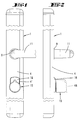
- Fig. 1
- eine Frontansicht eines türaußenseitig zu befestigenden Verschlusses,
- Fig. 2
- eine Seitenansicht des Verschlusses,
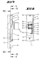
- Fig. 3
- eine Frontansicht des Verschlusses bei fortgelassenem Gehäuseschild,
- Fig. 4
- eine Seitansicht der Fig. 3, und zwar ebenfalls bei fortgelassenem Gehäuseschild, teilweise aufgebrochen, dargestellt,
- Fig. 5
- den Schnitt nach der Linie V-V in Fig. 4,
- Fig. 6
- den Schnitt nach der Linie VI-VI in Fig. 4,
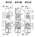
- Fig. 7
- eine Ansicht des komplettierten Einsatzgehäuses,
- Fig. 8
- die Ansicht gemäß Pfeilrichtung VIII-VIII in Fig. 7,
- Fig. 9
- die Ansicht gemäß Pfeilrichtung IX-IX der Fig. 7,
- Fig. 10
- die Ansicht gemäß Pfeilrichtung X-X in Fig. 7,
- Fig. 11
- eine Darstellung wie Fig. 9, jedoch bei vom Elektromotor gedrehter Kurvenscheibe, welche ihrerseits einen Schalter betätigt,
- Fig. 12
- den Schnitt nach der Linie XII-XII in Fig. 9,
- Fig. 13
- den Schnitt nach der Linie XIII-XIII in Fig. 11, wobei abweichend von Fig. 12 zusätzlich der Drehknauf entgegen Federbelastung in Einwärtsrichtung verlagert ist.
- Fig. 14
- den Schnitt nach der Linie XIV-XIV in Fig. 12 und
- Fig. 15
- den Schnitt nach der Linie XV-XV in Fig. 13
Claims (19)
- In Form eines auf das Türblatt anschlagbaren Beschlages ausgebildeter Verschluß (1) mit einem Gehäuse, einem Drehknauf (15) und einem Abtriebszapfen zur Betätigung eines Türschlosses, wobei der ansonsten leerdrehende Drehnauf (15) mittels einer bei Anwendung des richtigen Schließcodes elektrisch in Wirkung tretenden Kupplung mit dem Abtriebszapfen kuppelbar ist und wobei zum Empfang des Codes von einem Code-Sender eine Antenne vorgesehen ist, dadurch gekennzeichnet, dass die Antenne (37) ringförmig die Antriebswelle des Drehknaufes (15) umgibt.
- Verschluß nach einem oder mehreren der vorhergehenden Ansprüche oder insbesondere danach, dadurch gekennzeichnet, dass die Antenne (37) im Stirnbereich des Drehknaufes (15) liegt.
- Verschluß nach einem oder mehreren der vorhergehenden Ansprüche oder insbesondere danach, dadurch gekennzeichnet, dass die Antenne als Spule (37) auf einem von der Antriebswelle durchgriffenen Platine (13) sitzenden Spulenträger (35) sitzt.
- Verschluß nach einem oder mehreren der vorhergehenden Ansprüche oder insbesondere danach, dadurch gekennzeichnet, dass die Antenne (37) außen vor dem Gehäuseschild (4) sitzt.
- Verschluß nach einem oder mehreren der vorhergehenden Ansprüche oder insbesondere danach, dadurch gekennzeichnet, dass die Gehäuseschale (34) des Drehknaufes (15) gegenüber dem Spulenträger (35) drehbar und gegen Federkraft axial verlagerbar ist.
- Verschluß nach einem oder mehreren der vorhergehenden Ansprüche oder insbesondere danach, dadurch gekennzeichnet, dass einhergehend mit der Axialverlagerung der Gehäuseschale (34) ein parallel zur Platinenebene schwenkbar gelagerter Aktivierungshebel (40) schwenkt.
- Verschluß nach einem oder mehreren der vorhergehenden Ansprüche oder insbesondere danach, dadurch gekennzeichnet, dass der Aktivierungshebel (40) an seinem insbesondere langen Hebelarm (42) einen Magneten (44) trägt, der in der Verlagerungsstellung des Drehknaufes (15) einen Magnetschalter (45) betätigt.
- Verschluß nach einem oder mehreren der vorhergehenden Ansprüche oder insbesondere danach, dadurch gekennzeichnet, dass der insbesondere kurze Hebelarm (43) vom Drehknauf (15) kurvengesteuert wird.
- Verschluß nach einem oder mehreren der vorhergehenden Ansprüche oder insbesondere danach, gekennzeichnet durch eine in den Innenraum der Drehknauf-Gehäuseschale (34) hineinragende Innenhülse (33) mit ringsumlaufender, stirnseitiger Steuerschräge (47), welche mit einem Steuervorsprung (46) des Aktivierungshebels (40) zusammenwirkt.
- Verschluß nach einem oder mehreren der vorhergehenden Ansprüche oder insbesondere danach, dadurch gekennzeichnet, dass der Aktivierungshebel (40) um einen Befestigungszapfen (41) des Spulenträgers (35) gelagert ist.
- Verschluß nach einem oder mehreren der vorhergehenden Ansprüche oder insbesondere danach, dadurch gekennzeichnet, dass insbesonder der kurze Arm (43) des Aktivierungshebels (40) materialeinheitlich sich in einen Federarm (43') fortsetzt.
- Verschluß nach einem oder mehreren der vorhergehenden Ansprüche oder insbesondere danach, dadurch gekennzeichnet, dass ein Mitnehmerzapfen (31) der Kupplung (K) formschlüssig in die Höhlung (32) der Innenhülse (33) eingreift.
- Verschluß nach einem oder mehreren der vorhergehenden Ansprüche oder insbesondere danach, dadurch gekennzeichnet, dass das Kupplungslager (27) Durchtrittsöffnungen (26) für die Schenkel einer kurvengesteuerten Kupplungsfeder (25) besitzt.
- In Form eines auf das Türblatt anschlagbaren Beschlages ausgebildeter Verschluß (1) mit einem Gehäuse, einem Drehknauf (15) und einem Abtriebszapfen zur Betätigung eines Türschlosses, wobei der ansonsten leerdrehende Drehknauf (15) mittels einer bei Anwendung des richtigen Schließcodes elektrisch in Wirkung tretenden Kupplung mit dem Abtriebszapfen kuppelbar ist, wobei zum Empfang des Codes von einem Code-Sender eine Antenne (37) vorgesehen ist und wobei ein die Kupplung aktivierender Elektromotor vorgesehen ist, welcher zusammen mit einer die Antennen-Empfangsschaltung tragenden Platine (13) einem Einsatzgehäuse (3) zugeordnet ist, dadurch gekennzeichnet, dass das Einsatzgehäuse (3) inklusive der aus ihm rückwärts abragenden Abtriebswelle im Gehäuse in unterschiedliche Position zur Drückerlagerstelle einsetzbar ist.
- Verschluß nach Anspruch 14 oder insbesondere danach, dadurch gekennzeichnet, dass das Einsatzgehäuse (3) in einem U-förmigen Gehäuseabschnitt (2) verschieblich ist.
- Verschluß nach einem oder mehreren der vorhergehenden Ansprüche oder insbesondere danach, dadurch gekennzeichnet, dass das Einsatzgehäuse (3) mit seitlichen Schnappnasen (16) in Längsschlitze (17) der U-Schenkel (2') eingreift.
- Verschluß nach einem oder mehreren der vorhergehenden Ansprüche oder insbesondere danach, dadurch gekennzeichnet, dass das Einsatzgehäuse (3) aus einem ersten und einem zweiten Gehäuseteil (12, 14) besteht, wobei das erste Gehäuseteil (12) Träger des Motors (M), der Platine (13) und der Kupplung (K) ist, während das zweite Gehäuseteil (14), welches insbesondere die Schnappnasen (16) ausbildet, als Deckel gestaltet ist und den Drehknauf (15) trägt.
- Verschluß nach einem oder mehreren der vorhergehenden Ansprüche oder insbesondere danach, dadurch gekennzeichnet, dass der Deckel (14) mit einer Ausformung (18), in welcher sich Anzeigemittel (19, 20, 21) befinden, eine Aussparung (4') des Gehäuseschildes (4) durchgreift.
- Verschluß nach einem oder mehreren der vorhergehenden Ansprüche oder insbesondere danach, gekennzeichnet durch eine einen Rand (8) aufweisende Schnapphülse (7), deren Schnappfinger (10) in ein dem U-förmigen Gehäuseteil (2) zugeordnetes Drückerlager (6) eingreifen, welche Schnapphülse (7) mit dem Rand (8) auf dem Gehäuseschild (4) aufliegt und in ihrer Höhlung einen Drükkerflansch (11') eines Drückers (11) lagert.
Applications Claiming Priority (2)
| Application Number | Priority Date | Filing Date | Title |
|---|---|---|---|
| DE10006586A DE10006586A1 (de) | 2000-02-14 | 2000-02-14 | In Form eines auf das Türblatt anschlagbaren Beschlages ausgebildeter Verschluß |
| DE10006586 | 2000-02-14 |
Publications (3)
| Publication Number | Publication Date |
|---|---|
| EP1126104A2 true EP1126104A2 (de) | 2001-08-22 |
| EP1126104A3 EP1126104A3 (de) | 2001-11-14 |
| EP1126104B1 EP1126104B1 (de) | 2005-07-06 |
Family
ID=7630910
Family Applications (1)
| Application Number | Title | Priority Date | Filing Date |
|---|---|---|---|
| EP01103136A Expired - Lifetime EP1126104B1 (de) | 2000-02-14 | 2001-02-10 | Verschluss für Türen |
Country Status (3)
| Country | Link |
|---|---|
| EP (1) | EP1126104B1 (de) |
| AT (1) | ATE299219T1 (de) |
| DE (2) | DE10006586A1 (de) |
Cited By (2)
| Publication number | Priority date | Publication date | Assignee | Title |
|---|---|---|---|---|
| EP2060708A3 (de) * | 2007-11-05 | 2012-05-09 | SI-Technologies AG | Türschild für ein Schloss |
| WO2016040970A1 (de) * | 2014-09-15 | 2016-03-24 | Michael Makivic | Türschild für einen türbeschlag |
Families Citing this family (1)
| Publication number | Priority date | Publication date | Assignee | Title |
|---|---|---|---|---|
| DE102005039959B4 (de) * | 2005-08-24 | 2014-03-27 | Schulte-Schlagbaum Ag | Türbeschlag mit Außendrückerbetätigungssperre |
Family Cites Families (4)
| Publication number | Priority date | Publication date | Assignee | Title |
|---|---|---|---|---|
| JPH08240046A (ja) * | 1994-11-30 | 1996-09-17 | Texas Instr Inc <Ti> | 質問アンテナを有するキー・ロック及びその構築方法 |
| EP0730073A2 (de) * | 1995-03-03 | 1996-09-04 | Kaba Schliesssysteme AG | Schliessvorrichtung mit elektrischer Verriegelung |
| DE19618618A1 (de) * | 1996-05-09 | 1997-11-13 | Schulte Schlagbaum Ag | Auf einem Türblatt festlegbares Schloß |
| DE19832516A1 (de) * | 1998-07-20 | 2000-01-27 | Schulte Schlagbaum Ag | Schloß, insbesondere für eine Schließanlage |
-
2000
- 2000-02-14 DE DE10006586A patent/DE10006586A1/de not_active Withdrawn
-
2001
- 2001-02-10 EP EP01103136A patent/EP1126104B1/de not_active Expired - Lifetime
- 2001-02-10 AT AT01103136T patent/ATE299219T1/de active
- 2001-02-10 DE DE50106664T patent/DE50106664D1/de not_active Expired - Lifetime
Cited By (2)
| Publication number | Priority date | Publication date | Assignee | Title |
|---|---|---|---|---|
| EP2060708A3 (de) * | 2007-11-05 | 2012-05-09 | SI-Technologies AG | Türschild für ein Schloss |
| WO2016040970A1 (de) * | 2014-09-15 | 2016-03-24 | Michael Makivic | Türschild für einen türbeschlag |
Also Published As
| Publication number | Publication date |
|---|---|
| DE10006586A1 (de) | 2001-08-16 |
| EP1126104A3 (de) | 2001-11-14 |
| EP1126104B1 (de) | 2005-07-06 |
| DE50106664D1 (de) | 2005-08-11 |
| ATE299219T1 (de) | 2005-07-15 |
Similar Documents
| Publication | Publication Date | Title |
|---|---|---|
| EP1636454B1 (de) | Elektromechanischer schliesszylinder | |
| DE3906473C2 (de) | Schließverriegelung | |
| DE10261030A1 (de) | Bohrhammer | |
| DE4009276C2 (de) | Türverriegelungsvorrichtung | |
| DE3242527C2 (de) | Schloß für eine Kraftfahrzeugtür | |
| DE4311785C2 (de) | Kraftfahrzeugtürverschluß, der eine Schließ- und Öffnungshilfe mit motorischem Antrieb aufweist | |
| DE19548082A1 (de) | Doppelsperrschloß-Betätigungselement | |
| EP1332072B1 (de) | Vorrichtung mit einer lenkungsverriegelung sowie mit einem zündanlassschalter, die bei anwesenheit eines identifikationsgebers von einer handhabe steuerbar sind | |
| DE19905063A1 (de) | Türverriegelungsbaugruppe für Kraftfahrzeuge | |
| DE19923786A1 (de) | Schließzylinder | |
| DE19611752A1 (de) | Verschlußvorrichtung | |
| EP1126104B1 (de) | Verschluss für Türen | |
| DE102013216328A1 (de) | Schlossvorrichtung mit Schaltmechanismus | |
| DE4225153C1 (de) | ||
| DE69926038T2 (de) | Schloss mit automatischer Entriegelung beim Öffnen | |
| DE3924210C2 (de) | Türverriegelung | |
| EP1434706B1 (de) | Zündschloss | |
| EP0710970B1 (de) | Abschliessbare Handbetätigungsvorrichtung zum Ein- und Ausschalten von gekapselten elektrischen Schaltgeräten, insbesondere von Leistungsschaltern | |
| DE102004024253A1 (de) | Zündschloß für ein Kraftfahrzeug | |
| DE9210719U1 (de) | Türschloß | |
| DE10230586B4 (de) | Kraftfahrzeugtürverschluss | |
| DE3543166C2 (de) | ||
| DE2646739A1 (de) | Schlossanordnung | |
| DE19547577A1 (de) | Schließsystem, insbesondere für ein Kraftfahrzeug | |
| DE3627634A1 (de) | Drueckeranordnung an schloessern fuer tueren oder dergleichen |
Legal Events
| Date | Code | Title | Description |
|---|---|---|---|
| PUAI | Public reference made under article 153(3) epc to a published international application that has entered the european phase |
Free format text: ORIGINAL CODE: 0009012 |
|
| AK | Designated contracting states |
Kind code of ref document: A2 Designated state(s): AT BE CH CY DE DK ES FI FR GB GR IE IT LI LU MC NL PT SE TR |
|
| AX | Request for extension of the european patent |
Free format text: AL;LT;LV;MK;RO;SI |
|
| PUAL | Search report despatched |
Free format text: ORIGINAL CODE: 0009013 |
|
| AK | Designated contracting states |
Kind code of ref document: A3 Designated state(s): AT BE CH CY DE DK ES FI FR GB GR IE IT LI LU MC NL PT SE TR |
|
| AX | Request for extension of the european patent |
Free format text: AL;LT;LV;MK;RO;SI |
|
| 17P | Request for examination filed |
Effective date: 20020510 |
|
| AKX | Designation fees paid |
Free format text: AT BE CH CY DE DK ES FI FR GB GR IE IT LI LU MC NL PT SE TR |
|
| AXX | Extension fees paid |
Free format text: LT PAYMENT 20020510;LV PAYMENT 20020510;RO PAYMENT 20020510;SI PAYMENT 20020510 |
|
| 17Q | First examination report despatched |
Effective date: 20040729 |
|
| GRAP | Despatch of communication of intention to grant a patent |
Free format text: ORIGINAL CODE: EPIDOSNIGR1 |
|
| GRAS | Grant fee paid |
Free format text: ORIGINAL CODE: EPIDOSNIGR3 |
|
| GRAA | (expected) grant |
Free format text: ORIGINAL CODE: 0009210 |
|
| AK | Designated contracting states |
Kind code of ref document: B1 Designated state(s): AT BE CH CY DE DK ES FI FR GB GR IE IT LI LU MC NL PT SE TR |
|
| AX | Request for extension of the european patent |
Extension state: LT LV RO SI |
|
| PG25 | Lapsed in a contracting state [announced via postgrant information from national office to epo] |
Ref country code: IT Free format text: LAPSE BECAUSE OF FAILURE TO SUBMIT A TRANSLATION OF THE DESCRIPTION OR TO PAY THE FEE WITHIN THE PRESCRIBED TIME-LIMIT;WARNING: LAPSES OF ITALIAN PATENTS WITH EFFECTIVE DATE BEFORE 2007 MAY HAVE OCCURRED AT ANY TIME BEFORE 2007. THE CORRECT EFFECTIVE DATE MAY BE DIFFERENT FROM THE ONE RECORDED. Effective date: 20050706 Ref country code: IE Free format text: LAPSE BECAUSE OF FAILURE TO SUBMIT A TRANSLATION OF THE DESCRIPTION OR TO PAY THE FEE WITHIN THE PRESCRIBED TIME-LIMIT Effective date: 20050706 Ref country code: NL Free format text: LAPSE BECAUSE OF FAILURE TO SUBMIT A TRANSLATION OF THE DESCRIPTION OR TO PAY THE FEE WITHIN THE PRESCRIBED TIME-LIMIT Effective date: 20050706 Ref country code: TR Free format text: LAPSE BECAUSE OF FAILURE TO SUBMIT A TRANSLATION OF THE DESCRIPTION OR TO PAY THE FEE WITHIN THE PRESCRIBED TIME-LIMIT Effective date: 20050706 Ref country code: FI Free format text: LAPSE BECAUSE OF FAILURE TO SUBMIT A TRANSLATION OF THE DESCRIPTION OR TO PAY THE FEE WITHIN THE PRESCRIBED TIME-LIMIT Effective date: 20050706 |
|
| REG | Reference to a national code |
Ref country code: GB Ref legal event code: FG4D Free format text: NOT ENGLISH |
|
| REG | Reference to a national code |
Ref country code: CH Ref legal event code: EP |
|
| GBT | Gb: translation of ep patent filed (gb section 77(6)(a)/1977) |
Effective date: 20050706 |
|
| REG | Reference to a national code |
Ref country code: IE Ref legal event code: FG4D Free format text: LANGUAGE OF EP DOCUMENT: GERMAN |
|
| REF | Corresponds to: |
Ref document number: 50106664 Country of ref document: DE Date of ref document: 20050811 Kind code of ref document: P |
|
| REG | Reference to a national code |
Ref country code: CH Ref legal event code: NV Representative=s name: R. A. EGLI & CO. PATENTANWAELTE |
|
| PG25 | Lapsed in a contracting state [announced via postgrant information from national office to epo] |
Ref country code: DK Free format text: LAPSE BECAUSE OF FAILURE TO SUBMIT A TRANSLATION OF THE DESCRIPTION OR TO PAY THE FEE WITHIN THE PRESCRIBED TIME-LIMIT Effective date: 20051006 Ref country code: SE Free format text: LAPSE BECAUSE OF FAILURE TO SUBMIT A TRANSLATION OF THE DESCRIPTION OR TO PAY THE FEE WITHIN THE PRESCRIBED TIME-LIMIT Effective date: 20051006 Ref country code: GR Free format text: LAPSE BECAUSE OF FAILURE TO SUBMIT A TRANSLATION OF THE DESCRIPTION OR TO PAY THE FEE WITHIN THE PRESCRIBED TIME-LIMIT Effective date: 20051006 |
|
| PG25 | Lapsed in a contracting state [announced via postgrant information from national office to epo] |
Ref country code: ES Free format text: LAPSE BECAUSE OF FAILURE TO SUBMIT A TRANSLATION OF THE DESCRIPTION OR TO PAY THE FEE WITHIN THE PRESCRIBED TIME-LIMIT Effective date: 20051017 |
|
| PG25 | Lapsed in a contracting state [announced via postgrant information from national office to epo] |
Ref country code: PT Free format text: LAPSE BECAUSE OF FAILURE TO SUBMIT A TRANSLATION OF THE DESCRIPTION OR TO PAY THE FEE WITHIN THE PRESCRIBED TIME-LIMIT Effective date: 20051212 |
|
| LTIE | Lt: invalidation of european patent or patent extension |
Effective date: 20050706 |
|
| NLV1 | Nl: lapsed or annulled due to failure to fulfill the requirements of art. 29p and 29m of the patents act | ||
| REG | Reference to a national code |
Ref country code: IE Ref legal event code: FD4D |
|
| PG25 | Lapsed in a contracting state [announced via postgrant information from national office to epo] |
Ref country code: MC Free format text: LAPSE BECAUSE OF NON-PAYMENT OF DUE FEES Effective date: 20060228 Ref country code: BE Free format text: LAPSE BECAUSE OF NON-PAYMENT OF DUE FEES Effective date: 20060228 Ref country code: LU Free format text: LAPSE BECAUSE OF NON-PAYMENT OF DUE FEES Effective date: 20060228 |
|
| ET | Fr: translation filed | ||
| PLBE | No opposition filed within time limit |
Free format text: ORIGINAL CODE: 0009261 |
|
| STAA | Information on the status of an ep patent application or granted ep patent |
Free format text: STATUS: NO OPPOSITION FILED WITHIN TIME LIMIT |
|
| 26N | No opposition filed |
Effective date: 20060407 |
|
| BERE | Be: lapsed |
Owner name: SCHULTE-SCHLAGBAUM A.G. Effective date: 20060228 Owner name: FEIG ELECTRONIC G.M.B.H. Effective date: 20060228 |
|
| PG25 | Lapsed in a contracting state [announced via postgrant information from national office to epo] |
Ref country code: CY Free format text: LAPSE BECAUSE OF FAILURE TO SUBMIT A TRANSLATION OF THE DESCRIPTION OR TO PAY THE FEE WITHIN THE PRESCRIBED TIME-LIMIT Effective date: 20050706 |
|
| PGFP | Annual fee paid to national office [announced via postgrant information from national office to epo] |
Ref country code: CH Payment date: 20140217 Year of fee payment: 14 |
|
| PGFP | Annual fee paid to national office [announced via postgrant information from national office to epo] |
Ref country code: FR Payment date: 20140212 Year of fee payment: 14 Ref country code: AT Payment date: 20140212 Year of fee payment: 14 |
|
| PGFP | Annual fee paid to national office [announced via postgrant information from national office to epo] |
Ref country code: GB Payment date: 20140217 Year of fee payment: 14 |
|
| PGFP | Annual fee paid to national office [announced via postgrant information from national office to epo] |
Ref country code: DE Payment date: 20141224 Year of fee payment: 15 |
|
| REG | Reference to a national code |
Ref country code: CH Ref legal event code: PL |
|
| REG | Reference to a national code |
Ref country code: AT Ref legal event code: MM01 Ref document number: 299219 Country of ref document: AT Kind code of ref document: T Effective date: 20150210 |
|
| GBPC | Gb: european patent ceased through non-payment of renewal fee |
Effective date: 20150210 |
|
| PG25 | Lapsed in a contracting state [announced via postgrant information from national office to epo] |
Ref country code: CH Free format text: LAPSE BECAUSE OF NON-PAYMENT OF DUE FEES Effective date: 20150228 Ref country code: LI Free format text: LAPSE BECAUSE OF NON-PAYMENT OF DUE FEES Effective date: 20150228 |
|
| REG | Reference to a national code |
Ref country code: FR Ref legal event code: ST Effective date: 20151030 |
|
| PG25 | Lapsed in a contracting state [announced via postgrant information from national office to epo] |
Ref country code: AT Free format text: LAPSE BECAUSE OF NON-PAYMENT OF DUE FEES Effective date: 20150210 |
|
| PG25 | Lapsed in a contracting state [announced via postgrant information from national office to epo] |
Ref country code: GB Free format text: LAPSE BECAUSE OF NON-PAYMENT OF DUE FEES Effective date: 20150210 |
|
| PG25 | Lapsed in a contracting state [announced via postgrant information from national office to epo] |
Ref country code: FR Free format text: LAPSE BECAUSE OF NON-PAYMENT OF DUE FEES Effective date: 20150302 |
|
| REG | Reference to a national code |
Ref country code: DE Ref legal event code: R119 Ref document number: 50106664 Country of ref document: DE |
|
| PG25 | Lapsed in a contracting state [announced via postgrant information from national office to epo] |
Ref country code: DE Free format text: LAPSE BECAUSE OF NON-PAYMENT OF DUE FEES Effective date: 20160901 |