EP1126136A2 - Aube de turbine avec carenage d'extremité refroidie - Google Patents
Aube de turbine avec carenage d'extremité refroidie Download PDFInfo
- Publication number
- EP1126136A2 EP1126136A2 EP00810966A EP00810966A EP1126136A2 EP 1126136 A2 EP1126136 A2 EP 1126136A2 EP 00810966 A EP00810966 A EP 00810966A EP 00810966 A EP00810966 A EP 00810966A EP 1126136 A2 EP1126136 A2 EP 1126136A2
- Authority
- EP
- European Patent Office
- Prior art keywords
- turbine blade
- cooling
- blade according
- bores
- shroud element
- Prior art date
- Legal status (The legal status is an assumption and is not a legal conclusion. Google has not performed a legal analysis and makes no representation as to the accuracy of the status listed.)
- Granted
Links
Images


Classifications
-
- F—MECHANICAL ENGINEERING; LIGHTING; HEATING; WEAPONS; BLASTING
- F01—MACHINES OR ENGINES IN GENERAL; ENGINE PLANTS IN GENERAL; STEAM ENGINES
- F01D—NON-POSITIVE DISPLACEMENT MACHINES OR ENGINES, e.g. STEAM TURBINES
- F01D5/00—Blades; Blade-carrying members; Heating, heat-insulating, cooling or antivibration means on the blades or the members
- F01D5/12—Blades
- F01D5/14—Form or construction
- F01D5/18—Hollow blades, i.e. blades with cooling or heating channels or cavities; Heating, heat-insulating or cooling means on blades
- F01D5/187—Convection cooling
-
- F—MECHANICAL ENGINEERING; LIGHTING; HEATING; WEAPONS; BLASTING
- F01—MACHINES OR ENGINES IN GENERAL; ENGINE PLANTS IN GENERAL; STEAM ENGINES
- F01D—NON-POSITIVE DISPLACEMENT MACHINES OR ENGINES, e.g. STEAM TURBINES
- F01D5/00—Blades; Blade-carrying members; Heating, heat-insulating, cooling or antivibration means on the blades or the members
- F01D5/12—Blades
- F01D5/22—Blade-to-blade connections, e.g. for damping vibrations
- F01D5/225—Blade-to-blade connections, e.g. for damping vibrations by shrouding
-
- F—MECHANICAL ENGINEERING; LIGHTING; HEATING; WEAPONS; BLASTING
- F05—INDEXING SCHEMES RELATING TO ENGINES OR PUMPS IN VARIOUS SUBCLASSES OF CLASSES F01-F04
- F05D—INDEXING SCHEME FOR ASPECTS RELATING TO NON-POSITIVE-DISPLACEMENT MACHINES OR ENGINES, GAS-TURBINES OR JET-PROPULSION PLANTS
- F05D2240/00—Components
- F05D2240/80—Platforms for stationary or moving blades
- F05D2240/81—Cooled platforms
-
- F—MECHANICAL ENGINEERING; LIGHTING; HEATING; WEAPONS; BLASTING
- F05—INDEXING SCHEMES RELATING TO ENGINES OR PUMPS IN VARIOUS SUBCLASSES OF CLASSES F01-F04
- F05D—INDEXING SCHEME FOR ASPECTS RELATING TO NON-POSITIVE-DISPLACEMENT MACHINES OR ENGINES, GAS-TURBINES OR JET-PROPULSION PLANTS
- F05D2250/00—Geometry
- F05D2250/10—Two-dimensional
- F05D2250/14—Two-dimensional elliptical
- F05D2250/141—Two-dimensional elliptical circular
Definitions
- the present invention relates to the field of gas turbines. It affects an air-cooled turbine blade according to the preamble of claim 1.
- Such a turbine blade is e.g. from US-A-5,482,435 or US-A-5,785,496.
- the known cooling holes take up comparatively little space within the shroud element on. Because a certain minimum thickness is required to drill the holes in the shroud element of the shroud element is required, and this or an even larger one Thickness of the shroud element also in the area outside the holes is maintained, there is an unfavorably small ratio of the flow Shroud volume to shroud volume not flowed through. As a consequence, that the cooling of the shroud element is not optimal, and that the shroud element comparatively due to the large proportion of solid material is heavy and therefore high during operation due to the centrifugal forces is exposed to mechanical loads.
- the object is achieved by the entirety of the features of claim 1.
- the essence of the invention is that the cavities carrying the cooling fluid inside the Shroud element in coordination with the shroud element in shape and dimension To be designed so that the volume through which the cooling fluid flows occupies a high proportion of the total volume of the shroud element.
- the weight of the shroud element be significantly reduced.
- a first preferred embodiment of the turbine blade according to the invention is characterized in that the cavities include cooling holes, that the cooling holes are tunnel-shaped, the thickness of the Cover band element outside the cooling holes is reduced, and that the Cooling holes essentially parallel to the direction of movement of the blade tip run from the inside out and in front of the outer edge of the Open the cover band element upwards into the outside space.
- the tunnel-shaped The formation of the cooling bores not only reduces the proportion of solid material in the Shroud element, but also mechanically stiffens the shroud element. The cooling air escaping upwards can also escape unhindered if the shroud elements of all blades of a turbine stage are lined up an annular shroud.
- cooling holes open laterally into the recesses.
- a part of Cooling holes can also be designed as a diffuser.
- a second preferred embodiment of the invention is characterized in that that the cavities are designed as slits, which extend across the width of the shroud element extend that the slots substantially parallel to Direction of movement of the blade tip from the inside to the outside and each in front of the outer edge of the shroud element upwards into the outside space open into the cover band element from the top are embedded, and that the slots open laterally into the recesses.
- the wide slots result in good cooling with a significant reduction in material.
- Cooling is particularly effective if, according to a preferred further development this embodiment in the slots means for improving the heat transfer are provided between the cooling air and the shroud element.
- the slots can be used as a means of improving heat transfer distributed arrangement of pins include, which flows around the cooling fluid turbulent and so the heat transfer between cooling fluid and shroud material continue to improve.
- a third preferred embodiment of the turbine blade according to the invention is characterized in that the cavities are in the direction of movement of the blade tip extending cooling holes include that the cooling holes are crossed by a plurality of cross holes, and that the cross holes are blocked off from the outside by closed ends are.
- This configuration of the intersecting cooling holes is of geometry comparable to the previously mentioned wide slots with distributed pin arrangement.
- the solid material is used with greatly improved heat transfer of the shroud element significantly reduced and thus weight saved.
- the intersecting cooling holes can be compared with conventional means insert easily into the shroud element. In terms of cooling technology in particular Favorable cooling holes can be achieved if the cooling holes and the cross holes are made using the so-called "STEM drilling" process are.
- Fig. 1 is a first preferred embodiment in plan view from above the turbine blade according to the invention.
- the turbine blade 10 comprises the actual blade profile (extending perpendicular to the plane of the drawing) 23 and a shroud element arranged transversely thereto at the tip of the blade 11, which together with the shroud elements of the other (not shown) Buckets a continuous, ring-shaped, mechanically stabilizing Cover band results.
- the blade profile 23 is partially hollow inside and of one or several cooling air ducts 18 (indicated by dashed lines in FIG. 1), direct the cooling air from the blade root to the tip of the blade (see e.g. Fig. 2 of US-A-5,482,435).
- the cover band element 11 has on its upper side (22 in Fig. 2) two ribs running parallel in the direction of movement of the blade tip 12 and 13, which together with the opposite housing wall 20 of the gas turbine form a cavity 21 connected to the surroundings by gaps (FIG. 2).
- Cooling holes 16 'and 17, 17' Inside the shroud element 11 run between and essentially parallel to the ribs 12, 13 a plurality of cooling bores 16, 16 'and 17, 17' (in Fig. 1 and 2 shown in dashed lines) starting from the center outwards.
- the Cooling holes can be of a uniform shape, but can also be different be designed. 1 and 2 are the Cooling holes 16, 17 as holes with a largely constant diameter designed, while the cooling bores 16 ', 17' as diffusers with themselves in the direction of flow expanding cross-section are formed.
- the cooling bores 16, 16 'and 17, 17' are on the input side with the cooling air duct 18 in connection and are supplied by this with cooling air (or another Cooling fluid).
- the cooling bores extend 16, 17 not all the way to the side end or edge of the shroud element 11, but each open from the side into an elongated, from the Indentation 14 or 15 recessed into the cover band element 11 from the top side. This ensures that the cooling air always passes through the cooling holes, even if two (adjacent) shroud elements in mechanical Are in contact.
- each of the cooling bores 16, 16 'and 17, 17' taken for themselves can be connected to a separate depression. Still is it is also conceivable, the cooling holes 16, 16 'and 17, 17' slightly oblique and from one To allow parallelism to run differently when it comes to optimization cooling over the entire surface of the shroud element 11 is necessary is.
- FIG. 3 and 4 An alternative form of weight reduction is in the exemplary embodiment in FIG. 3 and 4 reproduced.
- 11 inside the shroud element instead a plurality of cooling holes on both sides of the blade profile Wide slot 25 or 26 is provided, each of which is from the central cooling air duct 18 extends to the lateral recesses 14 and 15 and opens there.
- the Slots 25, 26 lead to a considerable because of their continuous width Weight reduction and ensure a uniform over the entire width Distributed cooling Throttling points 19 and 19 'can also be used here for limitation of the cooling air mass flow may be provided, the throttling points in each case on the input side (throttling points 19) and / or the output side (throttling points 19 ') of the slots 25, 26 are positioned.
- Cooling through the slots 25, 26 can be further increased in their effect if as a means of improvement the heat transfer in the slots a distributed arrangement (one "array") is provided by pins 27.
- Pins 7 increase the turbulence of the Cooling air flow and represent additional areas for heat transfer. In addition, they have a mechanical stabilizing effect when they are in the slots range from wall to wall.
- the number and arrangement of the pins in the "array" can be changed in the Be changed as part of an optimization of the cooling effect.
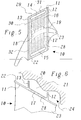
- Cooling holes 16, 17 (drilling axis 29) and these intersecting cross holes 28 (drilling axis 30) produces the effect in terms of weight loss and cooling comparable to the pin-occupied slots of FIGS. 3 and 4 is.
- Cooling bores 16, 17 and cross bores 28 with internal roughness such as To provide turbulators or fins. This leads to a significantly more efficient one Cooling because the shape of the cooling hole can be optimized.
- the cooling holes 16, 17 and cross holes 28 are to the side by after drilling closed ends 31 and 32 blocked off.
- the cooling bores 16, 17 have again preferably throttling points 19 and open into laterally arranged depressions 14, 15 open at the top
Landscapes
- Engineering & Computer Science (AREA)
- Mechanical Engineering (AREA)
- General Engineering & Computer Science (AREA)
- Turbine Rotor Nozzle Sealing (AREA)
Applications Claiming Priority (2)
| Application Number | Priority Date | Filing Date | Title |
|---|---|---|---|
| DE19963377A DE19963377A1 (de) | 1999-12-28 | 1999-12-28 | Turbinenschaufel mit aktiv gekühltem Deckbandelement |
| DE1996377 | 1999-12-28 |
Publications (3)
| Publication Number | Publication Date |
|---|---|
| EP1126136A2 true EP1126136A2 (fr) | 2001-08-22 |
| EP1126136A3 EP1126136A3 (fr) | 2004-05-19 |
| EP1126136B1 EP1126136B1 (fr) | 2006-06-14 |
Family
ID=7934748
Family Applications (1)
| Application Number | Title | Priority Date | Filing Date |
|---|---|---|---|
| EP00810966A Expired - Lifetime EP1126136B1 (fr) | 1999-12-28 | 2000-10-19 | Aube de turbine avec carenage d'extremité refroidie |
Country Status (4)
| Country | Link |
|---|---|
| US (1) | US6464460B2 (fr) |
| EP (1) | EP1126136B1 (fr) |
| CN (1) | CN1278018C (fr) |
| DE (2) | DE19963377A1 (fr) |
Families Citing this family (23)
| Publication number | Priority date | Publication date | Assignee | Title |
|---|---|---|---|---|
| US6869270B2 (en) * | 2002-06-06 | 2005-03-22 | General Electric Company | Turbine blade cover cooling apparatus and method of fabrication |
| EP1508668B1 (fr) | 2003-07-23 | 2006-12-20 | Alstom Technology Ltd | Procédé pour le reconditionnement et procédé pour la fabrication d'une aube de turbine |
| EP1515000B1 (fr) * | 2003-09-09 | 2016-03-09 | Alstom Technology Ltd | Aubage d'une turbomachine avec un carenage contouré |
| US20060280610A1 (en) * | 2005-06-13 | 2006-12-14 | Heyward John P | Turbine blade and method of fabricating same |
| GB2430170B (en) * | 2005-09-15 | 2008-05-07 | Rolls Royce Plc | Method of forming a cast component |
| US20070201980A1 (en) * | 2005-10-11 | 2007-08-30 | Honeywell International, Inc. | Method to augment heat transfer using chamfered cylindrical depressions in cast internal cooling passages |
| US7686581B2 (en) * | 2006-06-07 | 2010-03-30 | General Electric Company | Serpentine cooling circuit and method for cooling tip shroud |
| US7762774B2 (en) * | 2006-12-15 | 2010-07-27 | Siemens Energy, Inc. | Cooling arrangement for a tapered turbine blade |
| US7568882B2 (en) * | 2007-01-12 | 2009-08-04 | General Electric Company | Impingement cooled bucket shroud, turbine rotor incorporating the same, and cooling method |
| US8057177B2 (en) * | 2008-01-10 | 2011-11-15 | General Electric Company | Turbine blade tip shroud |
| US20090180894A1 (en) * | 2008-01-10 | 2009-07-16 | General Electric Company | Turbine blade tip shroud |
| US7946817B2 (en) * | 2008-01-10 | 2011-05-24 | General Electric Company | Turbine blade tip shroud |
| US7946816B2 (en) | 2008-01-10 | 2011-05-24 | General Electric Company | Turbine blade tip shroud |
| US8322986B2 (en) * | 2008-07-29 | 2012-12-04 | General Electric Company | Rotor blade and method of fabricating the same |
| GB0901129D0 (en) * | 2009-01-26 | 2009-03-11 | Rolls Royce Plc | Rotor blade |
| CH700686A1 (de) * | 2009-03-30 | 2010-09-30 | Alstom Technology Ltd | Schaufel für eine gasturbine. |
| CN102069365B (zh) * | 2009-11-25 | 2014-12-10 | 中国江南航天工业集团林泉电机厂 | 一种散热器的制造方法及散热器 |
| US8444372B2 (en) | 2011-02-07 | 2013-05-21 | General Electric Company | Passive cooling system for a turbomachine |
| EP2713009B1 (fr) * | 2012-09-26 | 2015-03-11 | Alstom Technology Ltd | Procédé et système de refroidissement pour refroidir des aubes d'au moins une rangée d'aubes dans une turbomachine rotative |
| CN107438717B (zh) * | 2015-04-15 | 2021-10-08 | 罗伯特·博世有限公司 | 自由梢端型轴流式风扇组件 |
| US10947898B2 (en) | 2017-02-14 | 2021-03-16 | General Electric Company | Undulating tip shroud for use on a turbine blade |
| JP6636668B1 (ja) * | 2019-03-29 | 2020-01-29 | 三菱重工業株式会社 | 高温部品、高温部品の製造方法及び流量調節方法 |
| US11255198B1 (en) * | 2021-06-10 | 2022-02-22 | General Electric Company | Tip shroud with exit surface for cooling passages |
Family Cites Families (17)
| Publication number | Priority date | Publication date | Assignee | Title |
|---|---|---|---|---|
| US3433015A (en) * | 1965-06-23 | 1969-03-18 | Nasa | Gas turbine combustion apparatus |
| US3527544A (en) * | 1968-12-12 | 1970-09-08 | Gen Motors Corp | Cooled blade shroud |
| GB1605335A (en) * | 1975-08-23 | 1991-12-18 | Rolls Royce | A rotor blade for a gas turbine engine |
| JPS5847104A (ja) * | 1981-09-11 | 1983-03-18 | Agency Of Ind Science & Technol | ガスタ−ビンのタ−ビン動翼 |
| JPH03194101A (ja) * | 1989-12-21 | 1991-08-23 | Toshiba Corp | ガスタービン冷却動翼 |
| US5197852A (en) * | 1990-05-31 | 1993-03-30 | General Electric Company | Nozzle band overhang cooling |
| GB9224241D0 (en) * | 1992-11-19 | 1993-01-06 | Bmw Rolls Royce Gmbh | A turbine blade arrangement |
| US5306401A (en) * | 1993-03-15 | 1994-04-26 | Fierkens Richard H J | Method for drilling cooling holes in turbine blades |
| GB2290833B (en) | 1994-07-02 | 1998-08-05 | Rolls Royce Plc | Turbine blade |
| JP3188105B2 (ja) * | 1994-07-11 | 2001-07-16 | 三菱重工業株式会社 | ガスタービンの動翼 |
| US5482435A (en) | 1994-10-26 | 1996-01-09 | Westinghouse Electric Corporation | Gas turbine blade having a cooled shroud |
| GB2298245B (en) * | 1995-02-23 | 1998-10-28 | Bmw Rolls Royce Gmbh | A turbine-blade arrangement comprising a cooled shroud band |
| US5785496A (en) | 1997-02-24 | 1998-07-28 | Mitsubishi Heavy Industries, Ltd. | Gas turbine rotor |
| JPH1113402A (ja) * | 1997-06-23 | 1999-01-19 | Mitsubishi Heavy Ind Ltd | ガスタービン冷却翼チップシュラウド |
| DE69931088T2 (de) * | 1998-02-04 | 2006-12-07 | Mitsubishi Heavy Industries, Ltd. | Gasturbinenlaufschaufel |
| DE59912323D1 (de) * | 1998-12-24 | 2005-09-01 | Alstom Technology Ltd Baden | Turbinenschaufel mit aktiv gekühltem Deckbandelememt |
| US6254345B1 (en) * | 1999-09-07 | 2001-07-03 | General Electric Company | Internally cooled blade tip shroud |
-
1999
- 1999-12-28 DE DE19963377A patent/DE19963377A1/de not_active Ceased
-
2000
- 2000-10-19 EP EP00810966A patent/EP1126136B1/fr not_active Expired - Lifetime
- 2000-10-19 DE DE50012982T patent/DE50012982D1/de not_active Expired - Lifetime
- 2000-11-30 US US09/725,722 patent/US6464460B2/en not_active Expired - Lifetime
- 2000-12-28 CN CN00137072.3A patent/CN1278018C/zh not_active Expired - Fee Related
Also Published As
| Publication number | Publication date |
|---|---|
| US6464460B2 (en) | 2002-10-15 |
| EP1126136A3 (fr) | 2004-05-19 |
| DE19963377A1 (de) | 2001-07-12 |
| CN1301911A (zh) | 2001-07-04 |
| US20010006600A1 (en) | 2001-07-05 |
| EP1126136B1 (fr) | 2006-06-14 |
| DE50012982D1 (de) | 2006-07-27 |
| CN1278018C (zh) | 2006-10-04 |
Similar Documents
| Publication | Publication Date | Title |
|---|---|---|
| EP1126136A2 (fr) | Aube de turbine avec carenage d'extremité refroidie | |
| EP1270873B1 (fr) | Aube de turbine à gaz | |
| EP1267039B1 (fr) | Configuration de refroidissement du bord de fuite d'une aube | |
| EP1013884A2 (fr) | Aube de turbine avec plateforme refroidie | |
| DE60018817T2 (de) | Gekühlte Gasturbinenschaufel | |
| EP1113145B1 (fr) | Aube pour turbine a gaz avec section de mesure sur le bord de fuite | |
| DE602005000449T2 (de) | Kühlung mit Mikrokanälen für eine Turbinenschaufel | |
| DE3789514T2 (de) | Gekühlte Gasturbinenschaufel. | |
| DE69822100T2 (de) | Turbinenschaufel | |
| DE69823236T2 (de) | Einrichtung zur kühlung von gasturbinenschaufeln und methode zu deren herstellung | |
| DE69302614T2 (de) | Gekühlte Schaufel für eine Turbomaschine | |
| DE69714960T3 (de) | Wirbelelementkonstruktion für Kühlkanäle eines Gasturbinenrotorschaufelblattes | |
| DE69816578T2 (de) | Turbinenschaufel mit Kühlung der Hinterkantenwurzel | |
| DE602004010965T2 (de) | Hohle Rotorschaufel eines Gasturbinentriebwerks | |
| EP2384393B1 (fr) | Aube refroidie pour turbine a gaz | |
| DE1946535B2 (de) | Bauteil für ein Gasturbinentriebwerk | |
| EP1260678A1 (fr) | Dispositif de refroidissement pour les éléments d'une turbine à gaz | |
| DE19634238A1 (de) | Kühlbare Schaufel | |
| DE112020004602B4 (de) | Turbinenflügel | |
| DE102017110051A1 (de) | Schaufel mit belastungsreduzierendem bauchigem Vorsprung an einer Wendeöffnung von Kühlmittelkanälen | |
| DE69925447T2 (de) | Kühlbare Schaufelblätter | |
| DE112019000898B4 (de) | Turbinenschaufel und gasturbine | |
| DE60019965T2 (de) | Axialturbine für gase | |
| EP1167689A1 (fr) | Configuration d'une aube de turbine refroidissable | |
| EP0892150B1 (fr) | Système de refroidissement pour le bord de fuite des aubes creuses d'une turbine à gaz |
Legal Events
| Date | Code | Title | Description |
|---|---|---|---|
| PUAI | Public reference made under article 153(3) epc to a published international application that has entered the european phase |
Free format text: ORIGINAL CODE: 0009012 |
|
| AK | Designated contracting states |
Kind code of ref document: A2 Designated state(s): AT BE CH CY DE DK ES FI FR GB GR IE IT LI LU MC NL PT SE |
|
| AX | Request for extension of the european patent |
Free format text: AL;LT;LV;MK;RO;SI |
|
| RAP1 | Party data changed (applicant data changed or rights of an application transferred) |
Owner name: ALSTOM (SWITZERLAND) LTD |
|
| RAP1 | Party data changed (applicant data changed or rights of an application transferred) |
Owner name: ALSTOM TECHNOLOGY LTD |
|
| PUAL | Search report despatched |
Free format text: ORIGINAL CODE: 0009013 |
|
| AK | Designated contracting states |
Kind code of ref document: A3 Designated state(s): AT BE CH CY DE DK ES FI FR GB GR IE IT LI LU MC NL PT SE |
|
| AX | Request for extension of the european patent |
Extension state: AL LT LV MK RO SI |
|
| RIC1 | Information provided on ipc code assigned before grant |
Ipc: 7F 01D 11/24 B Ipc: 7F 01D 5/20 A Ipc: 7F 01D 11/08 B Ipc: 7F 01D 5/18 B |
|
| 17P | Request for examination filed |
Effective date: 20041112 |
|
| AKX | Designation fees paid |
Designated state(s): DE GB |
|
| 17Q | First examination report despatched |
Effective date: 20050216 |
|
| GRAP | Despatch of communication of intention to grant a patent |
Free format text: ORIGINAL CODE: EPIDOSNIGR1 |
|
| GRAS | Grant fee paid |
Free format text: ORIGINAL CODE: EPIDOSNIGR3 |
|
| GRAA | (expected) grant |
Free format text: ORIGINAL CODE: 0009210 |
|
| RIN1 | Information on inventor provided before grant (corrected) |
Inventor name: EL-NASHAR, IBRAHIM, DR. Inventor name: HAEHNLE, HARTMUT Inventor name: VON ARX, BEAT Inventor name: KELLERER, RUDOLF Inventor name: WEIGAND, BERNHARD, PROF.DR. |
|
| AK | Designated contracting states |
Kind code of ref document: B1 Designated state(s): DE GB |
|
| REG | Reference to a national code |
Ref country code: GB Ref legal event code: FG4D Free format text: NOT ENGLISH |
|
| REF | Corresponds to: |
Ref document number: 50012982 Country of ref document: DE Date of ref document: 20060727 Kind code of ref document: P |
|
| GBT | Gb: translation of ep patent filed (gb section 77(6)(a)/1977) |
Effective date: 20060906 |
|
| PLBE | No opposition filed within time limit |
Free format text: ORIGINAL CODE: 0009261 |
|
| STAA | Information on the status of an ep patent application or granted ep patent |
Free format text: STATUS: NO OPPOSITION FILED WITHIN TIME LIMIT |
|
| 26N | No opposition filed |
Effective date: 20070315 |
|
| REG | Reference to a national code |
Ref country code: DE Ref legal event code: R082 Ref document number: 50012982 Country of ref document: DE Representative=s name: ROESLER, UWE, DIPL.-PHYS.UNIV., DE Ref country code: DE Ref legal event code: R081 Ref document number: 50012982 Country of ref document: DE Owner name: GENERAL ELECTRIC TECHNOLOGY GMBH, CH Free format text: FORMER OWNER: ALSTOM TECHNOLOGY LTD., BADEN, CH Ref country code: DE Ref legal event code: R081 Ref document number: 50012982 Country of ref document: DE Owner name: ANSALDO ENERGIA IP UK LIMITED, GB Free format text: FORMER OWNER: ALSTOM TECHNOLOGY LTD., BADEN, CH |
|
| REG | Reference to a national code |
Ref country code: DE Ref legal event code: R082 Ref document number: 50012982 Country of ref document: DE Representative=s name: ROESLER, UWE, DIPL.-PHYS.UNIV., DE Ref country code: DE Ref legal event code: R081 Ref document number: 50012982 Country of ref document: DE Owner name: ANSALDO ENERGIA IP UK LIMITED, GB Free format text: FORMER OWNER: GENERAL ELECTRIC TECHNOLOGY GMBH, BADEN, CH |
|
| REG | Reference to a national code |
Ref country code: GB Ref legal event code: 732E Free format text: REGISTERED BETWEEN 20170824 AND 20170830 |
|
| PGFP | Annual fee paid to national office [announced via postgrant information from national office to epo] |
Ref country code: DE Payment date: 20171019 Year of fee payment: 18 |
|
| PGFP | Annual fee paid to national office [announced via postgrant information from national office to epo] |
Ref country code: GB Payment date: 20171019 Year of fee payment: 18 |
|
| REG | Reference to a national code |
Ref country code: DE Ref legal event code: R119 Ref document number: 50012982 Country of ref document: DE |
|
| GBPC | Gb: european patent ceased through non-payment of renewal fee |
Effective date: 20181019 |
|
| PG25 | Lapsed in a contracting state [announced via postgrant information from national office to epo] |
Ref country code: DE Free format text: LAPSE BECAUSE OF NON-PAYMENT OF DUE FEES Effective date: 20190501 |
|
| PG25 | Lapsed in a contracting state [announced via postgrant information from national office to epo] |
Ref country code: GB Free format text: LAPSE BECAUSE OF NON-PAYMENT OF DUE FEES Effective date: 20181019 |