EP1126204A2 - Flüssigkeitsundurchlässiger Verbundschlauch - Google Patents
Flüssigkeitsundurchlässiger Verbundschlauch Download PDFInfo
- Publication number
- EP1126204A2 EP1126204A2 EP01103250A EP01103250A EP1126204A2 EP 1126204 A2 EP1126204 A2 EP 1126204A2 EP 01103250 A EP01103250 A EP 01103250A EP 01103250 A EP01103250 A EP 01103250A EP 1126204 A2 EP1126204 A2 EP 1126204A2
- Authority
- EP
- European Patent Office
- Prior art keywords
- layer
- laminated
- hose
- thread
- rubber layer
- Prior art date
- Legal status (The legal status is an assumption and is not a legal conclusion. Google has not performed a legal analysis and makes no representation as to the accuracy of the status listed.)
- Granted
Links
Images


Classifications
-
- F—MECHANICAL ENGINEERING; LIGHTING; HEATING; WEAPONS; BLASTING
- F16—ENGINEERING ELEMENTS AND UNITS; GENERAL MEASURES FOR PRODUCING AND MAINTAINING EFFECTIVE FUNCTIONING OF MACHINES OR INSTALLATIONS; THERMAL INSULATION IN GENERAL
- F16L—PIPES; JOINTS OR FITTINGS FOR PIPES; SUPPORTS FOR PIPES, CABLES OR PROTECTIVE TUBING; MEANS FOR THERMAL INSULATION IN GENERAL
- F16L11/00—Hoses, i.e. flexible pipes
- F16L11/04—Hoses, i.e. flexible pipes made of rubber or flexible plastics
- F16L11/08—Hoses, i.e. flexible pipes made of rubber or flexible plastics with reinforcements embedded in the wall
- F16L11/085—Hoses, i.e. flexible pipes made of rubber or flexible plastics with reinforcements embedded in the wall comprising one or more braided layers
Definitions
- This invention relates to a fluid-impermeable composite hose. More particularly, it relates to a fluid-impermeable composite hose having a fluid-impermeable laminated layer formed of a laminated sheet containing a metallic foil, or a metallic layer formed by vapor deposition.
- the hose of this invention is particularly useful as a fluid-impermeable hose for transporting any of various kinds of fluids in a motor vehicle.
- Every hose used for transporting a refrigerant in an air-conditioning system on a motor vehicle is required to be impermeable to the refrigerant. This is particularly the case with any hose for transporting e.g. an alternative to chlorofluorocarbons, or carbon dioxide as a refrigerant in view of system maintenance, environmental protection, etc.
- One of the most effective approaches is a hose having a laminated wall layer containing a metallic foil, or a metallic layer formed by vapor deposition.
- Environmental protection also requires a fuel hose to be impermeable to fuel, and a laminated wall layer is very useful for a fuel hose, too.
- a laminated wall layer for a hose It has been usual to form a laminated wall layer for a hose by longitudinal lapping or spiral winding of a tape of a laminated sheet containing a metallic foil, or a metallic layer formed by vapor deposition.
- Longitudinal lapping is a method in which a tape of a laminated sheet having a width large enough to encircle a hose to be made is placed in parallel to the longitudinal axis of the hose and bent into a cylindrical layer having a pair of overlapping edge portions.
- Spiral winding is a method in which a tape of a laminated sheet is wound in a spirally overlapping way to form a cylindrical layer.
- Longitudinal lapping has a number of advantages over spiral winding, as stated below.
- a cylindrical layer can be formed more rapidly by longitudinal lapping. Then, it can be carried out in tandem with a step of rubber extrusion preceding or following it.
- the overlapping edge portions formed by longitudinal lapping have a smaller length which means that a hose has a higher fluid impermeability.
- a laminated sheet is, however, a multilayer structure having spring elasticity. While it does not exhibit a very high bending resistance for spiral winding, it exhibits a high bending resistance for longitudinal lapping as it has to be bent across its width. Its bending resistance tends to cause the separation of the overlapping edge portions from each other. As a result, it is likely that a hose having a layer formed by longitudinal lapping may not retain an accurately circular shape in cross section, but may have a deformed circular shape. Moreover, the separation of the overlapping edge portions joined together may result in the failure of the hose to retain its fluid impermeability. Even if an intermediate rubber layer, or a thin resin layer may be extruded about the laminated layer, its binding force is not sufficiently strong to overcome the bending resistance of the laminated sheet.
- a hose having a laminated layer formed by longitudinal lapping is less easy to bend, since the overlapping edge portions of the laminated sheet extend longitudinally of the hose. In other words, it is usually inferior in overall flexibility to any hose having a spirally wound wall layer.
- the inventors of this invention have found that it is effective to bind a longitudinally lapped tape of a laminated sheet by winding thread about it at a low density.
- the inventors have also found that it is effective to line a laminated layer with a rubber layer and rely upon its elastic deformation for causing the strong binding force of the wound thread to make constrictions in the laminated layer.
- a fluid-impermeable composite hose having a wall comprising a laminated layer formed of a laminated sheet which contains a metallic foil, or a metallic layer formed by vapor deposition, wherein the laminated layer is formed by longitudinally lapping a tape of the laminated sheet, and is bound with thread wound about it at a density not exceeding 20%.
- the high bending resistance of the laminated sheet is effectively suppressed by the thread wound about it. Therefore, there is no deformation of the hose in its cross sectional shape. Moreover, there is no separation of the overlapping edge portions of the laminated layer which may cause the loss of the fluid impermeability of the hose.
- the thread is essentially different in construction and effect from any reinforcing yarn layer formed usually on a hose.
- the reinforcing yarn layer is intended for improving the strength of the hose. It is formed of reinforcing yarn wound spirally or braided at a high density, even though it may lower the flexibility of the hose to some extent or other.
- the thread employed according to this invention is wound only at a density not exceeding 20%, and does not lower the flexibility of the hose. It is exclusively intended for suppressing the bending resistance of the laminated layer, and its density not exceeding 20% is sufficient for that purpose.
- a rubber layer on an inner periphery of the laminated layer and the laminated layer has constrictions formed by the thread owing to the elastic deformation of the rubber layer.
- the constrictions make the hose easier to bend and improve its flexibility. If the thread is wound at a high density, the constrictions do not have a sufficiently large depth to improve the flexibility of the hose effectively.
- the thread density not exceeding 20% is, however, low enough to ensure that the constrictions have a sufficiently large depth to improve the flexibility of the hose effectively.
- the constrictions are very unlikely to cause e.g. the fracture of the metallic foil in the laminated layer unless the hose is repeatedly subjected to an extremely high pressure or large displacement.
- the hose is particularly suitable for use as, for example, a fuel hose which is unlikely to be subjected to a high pressure or a large displacement.
- the constrictions are formed by the tension of the thread and/or its dry heat contraction. These are particularly effective ways of forming the constrictions.
- the constrictions formed by the tension of the thread are formed when it is wound, while those formed by its dry heat contraction are formed when the hose is heated as for curing.
- the laminated layer has a smooth outer surface not having any constriction formed by the thread.
- a laminated layer is particularly unlikely to have its metallic foil broken when the hose is repeatedly subjected to a high pressure or a large displacement, though it cannot be expected to give the hose any such improved flexibility as is given by the constrictions in the second aspect of this invention.
- the hose is particularly suitable for use as a refrigerant hose which is very likely to be repeatedly subjected to a high pressure, or a large displacement, especially a hose for a carbon dioxide refrigerant.
- the laminated layer is preferably lined with a layer of a resin, or any other hard material which is not easily deformable, while the thread is preferably of a material having only a low degree of dry heat contraction, so that the laminated layer may retain a smooth outer surface, while the thread can bind the laminated layer strongly enough to overcome the bending resistance of its overlapping edge portions joined together.
- the thread is preferably of polyethylene terephthalate (PET), polyamide (PA), rayon, aramid (aromatic polyamide), polyethylene naphthalate (PEN), or polyvinyl alcohol fibers.
- the thread for binding the laminated layer may be of any kind, however, it is desireable to use the thread of PET, PA, rayon, aramid, PEN, or polyvihyl alcohol fibers as in the fifth aspect.
- the laminated sheet is preferably composed of a resin film laminated on (1) a metallic foil, (2) a metallic foil and a reinforcing material, or (3) a metallic layer formed by vapor deposition.
- a metallic foil and a reinforcing material is particularly preferred for the laminated layer having constrictions formed therein.
- the fluid-impermeable composite hose of this invention is useful as a hose for transporting any of various kinds of fluids. It is particularly suitable as a hose for a refrigerant or fuel, and still more suitable for use in a motor vehicle because of its flexibility to withstand any vibration of a running vehicle or its engine.
- the hose according to the fourth aspect of this invention which has no constriction in its laminated wall layer, is, for example, suitable as a hose for a carbon dioxide refrigerant because of its durability to withstand a large displacement or a repeatedly applied high pressure.
- the hose according to the second aspect of this invention which has constrictions, is suitable because of its flexibility as, for example, a fuel hose which is not subjected to a very large displacement or a very high pressure.
- the fluid-impermeable composite hose has in its wall a laminated layer formed by longitudinally lapping a tape of a laminated sheet and bound with thread wound about it at a density not exceeding 20%.
- a laminated layer formed by longitudinally lapping a tape of a laminated sheet and bound with thread wound about it at a density not exceeding 20%.
- Both of the hoses as shown at (a) and (b) have a rubber layer located immediately inwardly of their laminated layer. It is preferable to bind the laminated layer of each of these hoses with thread so strongly as to form constrictions in that layer, though it is alternatively possible to bind the layer with thread to the extent not forming any such constriction.
- the constrictions make the hose flexible enough to be suitable as, for example, a fuel hose.
- the hose as shown at (a) is particularly high in fuel impermeability owing to the innermost resin layer of its wall.
- Both of the hoses as shown at (c) and (d) have a resin layer located immediately inwardly of their laminated layer.
- Each of these hoses is easy to bind with thread, while retaining a smooth outer surface on its laminated layer, since the resin layer is not easily deformable.
- they are suitable as highly durable hoses for transporting a refrigerant, particularly a highly permeant one, such as carbon dioxide.
- the hose as shown at (d) is particularly strong in the metallic foil in the laminated layer, since the layer is secured and protected between the inner and outer resin layers.
- the laminated layer is formed by longitudinally lapping a tape of a laminated sheet containing a metallic foil, or a metallic layer formed by vapor deposition, and is bound with thread wound about it at a density not exceeding 20%.
- the thread keeps the joining portions of the laminated sheet from projecting radially outwardly and thereby holds the hose substantially circular in cross section.
- the laminated sheet applied by longitudinal lapping preferably has a pair of widthwise edge portions overlapping each other to some extent.
- the overlapping edge portions are preferably joined to each other with an adhesive or a layer of an adhesive material, or by fusion under heat.
- the thread can be wound in any way if it can bind the laminated layer effectively.
- a single thread may be wound spirally.
- Two or more threads may be wound spirally in the same direction.
- Two threads may be wound spirally in the opposite directions in which they cross each other.
- Two or more sets of two or more threads each may be wound spirally in the opposite directions.
- the thread (or threads) is preferably bonded to the laminated layer by any appropriate method, but may not be bonded.
- the thread may be of any thickness and material if it is sufficiently high in tensile strength and durability to exert a satisfactory binding force on the laminated layer. For example, however, it is suitable to use a thread having a thickness of, say, 100 to 3000 deniers and a tensile strength of, say, 5 to 500 N.
- the binding force of the thread may be at least large enough to keep the overlapping edge portions of the laminated sheet from projecting radially outwardly of the hose according to the fourth aspect of this invention.
- the force may be at least large enough to form constrictions in the laminated layer.
- the force cannot be expressed by any specific numerical value, since it depends on the hardness of the laminated sheet, the diameter of the laminated layer, the softness of the rubber layer in the hose according to the second aspect of this invention, etc.
- the thread may be of any material including PET, PA, rayon, aramid, PEN and polyvinyl alcohol fibers. It is, however, preferably of PET or PA fibers having a relatively high degree of heat contractibility to form constrictions in the laminated layer, or of aramid fibers having a relatively low degree of heat contractibility to maintain a smooth outer surface on the laminated layer.
- the magnitude (or depth) of the constrictions to be formed in the laminated layer depends on the flexibility required of the hose. Therefore, it cannot be defined by any specific numerical value. They are, however, preferably of a depth formed by the thread slightly cutting into the outer surface of the laminated layer, or any greater visually recognizable depth.
- the laminated sheet forming the laminated layer is in the form of a tape containing a metallic foil, or a metallic layer formed by vapor deposition. It is preferably formed by laminating a resin film or films on (1) a metallic foil, (2) a combination of a metallic foil and a reinforcing material, or (3) a metallic layer formed by vapor deposition.
- a laminated sheet containing a metallic foil, or a combination thereof with a reinforcing material is usually formed by sandwiching it between two resin films, and bonding them together adhesively or by fusion.
- a laminated sheet containing a metallic layer formed by vapor deposition can be formed by forming a metallic layer by vapor deposition on one side of a resin film, and bonding another resin film to that side.
- a laminated sheet may also be formed by forming a metallic layer by vapor deposition on one side of each of two resin films, and bonding the films together on their sides carrying the metallic layers.
- the reinforcing material does not necessarily have to be bonded to the metallic foil, but can reinforce the foil more effectively if it is bonded.
- the reinforcing material is preferably located radially outwardly of the metallic foil.
- the metallic foil and its reinforcing material may or may not be bonded to the resin films.
- the reinforcing material may be of any kind, but is preferably one having a high stretch resistance and a high flexibility.
- Preferred examples are a wire mesh and a reinforcing fabric.
- the reinforcing fabric may be a canvas, or nonwoven fabric formed preferably of e.g. aramid, carbon or glass fibers of low stretchability.
- Another preferred example is a resin film of high strength.
- the thickness and hardness of the resin films, those of the laminated sheet as a whole, etc. affect the bending resistance of the laminated sheet formed by longitudinal lapping and the flexibility of the hose.
- the resin films may be of any resin, but are preferably of, for example, PA, PET or EVOH. These materials are also preferred because of their high stretch resistance to protect the metallic foil against fracture.
- the resin films preferably have a thickness not exceeding, say, 100 ⁇ m, and the laminated sheet as a whole preferably has a thickness not exceeding, say, 300 ⁇ m.
- a resin layer in the form of a thin film may be formed inwardly of the laminated layer, or outwardly thereof, too.
- the resin layer formed inwardly of the laminated layer enables it to retain a smooth outer surface despite the thread wound about it and also improves the impermeability of the hose to a refrigerant, etc.
- the resin layers formed both inwardly and outwardly secure and protect the laminated layer in a sandwiched manner, as well as improve the fluid impermeability of the hose.
- the resin layer (or layers) is preferably of, for example, EVOH, PA or a mixture of PA and a modified polyolefin, and has a thickness not exceeding, say, 300 ⁇ m.
- the intermediate rubber layer (or layers) provided in the predetermined portion at the fluid-impermeable composite hose serves to reduce or absorb any bending or deforming force acting upon the hose, so that no such force may reach the laminated layer and cause the metallic foil to break.
- the intermediate rubber layer is preferably of a rubber material which is highly impermeable to a refrigerant, etc., flexible, and easy to bond at a high temperature to the laminated, or reinforcing layer.
- Preferred examples are butyl rubber (IIR), halogenated IIR, ethylene-propylene rubber (EPM), ethylene-propylene-diene rubber (EPDM) and nitrile rubber (NBR). It preferably has a thickness of, say, 0.2 to 2.0 mm.
- the hose preferably has a reinforcing layer in its wall.
- the reinforcing layer may, for example, be a braided wire layer, or a layer formed by braiding reinforcing yarn, or winding reinforcing yarn spirally, or in two spiral layers extending in the opposite directions, or placing an intermediate rubber layer between two such spiral layers.
- An outer rubber layer may form the outermost wall layer of the hose. It may be of any rubber of high weatherability, such as chloroprene rubber (CR), IIR, chlorosulfonated polyethylene rubber (CSM), EPDM or epichlorohydrin rubber (ECO).
- CR chloroprene rubber
- IIR chloroprene rubber
- CSM chlorosulfonated polyethylene rubber
- EPDM epichlorohydrin rubber
- a fuel hose 1 has a resin layer 2 as the innermost layer of its wall and a first intermediate rubber layer 3 formed about it from IIR.
- the intermediate rubber layer 3 is surrounded by a laminated layer 6 formed by longitudinally lapping a tape of a laminated sheet 4 and bound with two threads 5 wound about it spirally in the opposite directions.
- the threads 5 bind the laminated layer 6 to an extent forming therein constrictions having a certain depth, but not shown.
- the laminated layer 6 is surrounded by a second intermediate rubber layer 7 of IIR, then a reinforcing layer 8 formed by braiding an appropriate reinforcing yarn, and finally an outer rubber layer 9 of EPDM.
- FIG. 2 shows a fuel hose 10 having an inner rubber layer 11 formed from fluororubber (FKM), and surrounded by a laminated layer 6 formed as described above, an intermediate rubber layer 7 of NBR, a reinforcing layer 8 and an outer rubber layer 9 of ECO.
- FKM fluororubber
- FIG. 3 shows a hose 12 for a carbon dioxide refrigerant having, outwardly of an inner resin layer 13 formed from a PA resin, a laminated layer 14 formed by longitudinal lapping of a tape of laminated sheet 4 and bound with threads 5 to an extent not forming any constriction therein, and allowing the layer 14 to retain a smooth outer surface.
- the laminated layer 14 is surrounded by an intermediate rubber layer 7 of IIR, then a reinforcing layer 8 and finally an outer rubber layer 9 of EPDM.
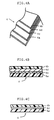
- the laminated sheet 4 is as shown in FIGS. 4A and 4B. It has an inner resin layer 4a formed by a thin film of a thermoplastic PET resin, a similar outer resin layer 4b, an aluminum foil 4c and a reinforcing material 4d in the form of a resin sheet, the foil 4c and the reinforcing material 4d being sandwiched between the inner and outer resin layers.
- the resin layers 4a and 4b are greater in width than the foil 4c and the reinforcing material 4d, and are joined to each other along their lateral edges.
- the foil 4c is bonded to the reinforcing material 4d with an adhesive not shown, so that no tensile or like force acting upon the laminated sheet 4 may act upon the foil 4c held by the reinforcing material 4d.
- FIG. 4C shows a modified form of laminated sheet 4. It does not have any reinforcing material as shown at 4d above, but has only a metallic foil 4c sandwiched between two resin layers 4a and 4b.
Landscapes
- Engineering & Computer Science (AREA)
- General Engineering & Computer Science (AREA)
- Mechanical Engineering (AREA)
- Rigid Pipes And Flexible Pipes (AREA)
- Laminated Bodies (AREA)
Applications Claiming Priority (2)
| Application Number | Priority Date | Filing Date | Title |
|---|---|---|---|
| JP2000043539 | 2000-02-16 | ||
| JP2000043539A JP3903679B2 (ja) | 2000-02-16 | 2000-02-16 | 非透過型複合ホース |
Publications (3)
| Publication Number | Publication Date |
|---|---|
| EP1126204A2 true EP1126204A2 (de) | 2001-08-22 |
| EP1126204A3 EP1126204A3 (de) | 2002-04-17 |
| EP1126204B1 EP1126204B1 (de) | 2004-06-09 |
Family
ID=18566445
Family Applications (1)
| Application Number | Title | Priority Date | Filing Date |
|---|---|---|---|
| EP01103250A Expired - Lifetime EP1126204B1 (de) | 2000-02-16 | 2001-02-12 | Flüssigkeitsundurchlässiger Verbundschlauch |
Country Status (4)
| Country | Link |
|---|---|
| US (1) | US6390140B2 (de) |
| EP (1) | EP1126204B1 (de) |
| JP (1) | JP3903679B2 (de) |
| DE (1) | DE60103673T2 (de) |
Cited By (4)
| Publication number | Priority date | Publication date | Assignee | Title |
|---|---|---|---|---|
| EP1418375A1 (de) * | 2002-11-05 | 2004-05-12 | Veritas Ag | Mehrschichtiger flexibler Schlauch |
| EP1614949A1 (de) * | 2004-05-28 | 2006-01-11 | Manifattura Gomma Finnord S.P.A. | Hydraulikschlauch, insbesondere für Bremssysteme, mit zugfestem Verstärkungsgeflecht und Kunststoffbeschichtung |
| EP1726860A1 (de) * | 2005-05-23 | 2006-11-29 | Ivg Colbachni S.P.A. | Flexibler Schlauch für Kraftstoffe und dessen Herstellungsverfahren |
| EP1974903A1 (de) * | 2007-03-29 | 2008-10-01 | Tokai Rubber Industries, Ltd. | Niedriger gasdurchlässiger Schlauch |
Families Citing this family (36)
| Publication number | Priority date | Publication date | Assignee | Title |
|---|---|---|---|---|
| US7498509B2 (en) * | 1995-09-28 | 2009-03-03 | Fiberspar Corporation | Composite coiled tubing end connector |
| US8678042B2 (en) | 1995-09-28 | 2014-03-25 | Fiberspar Corporation | Composite spoolable tube |
| US5921285A (en) | 1995-09-28 | 1999-07-13 | Fiberspar Spoolable Products, Inc. | Composite spoolable tube |
| DE19837497A1 (de) | 1998-08-13 | 2000-02-24 | Trinova Aeroquip Gmbh | Flexibler strangförmiger Hohlkörper |
| DE19837498A1 (de) * | 1998-08-13 | 2000-02-24 | Trinova Aeroquip Gmbh | Flexibler strangförmiger Hohlkörper |
| US6945279B2 (en) * | 2000-09-29 | 2005-09-20 | Yamashita Rubber Kabushiki Kaisha | Thin-walled rubber hose and method of producing the same |
| US6648023B2 (en) * | 2000-09-26 | 2003-11-18 | The Yokohama Rubber Co., Ltd. | Low permeable hose and method for producing the same |
| US20020185188A1 (en) * | 2001-04-27 | 2002-12-12 | Quigley Peter A. | Composite tubing |
| US20030070720A1 (en) * | 2001-09-27 | 2003-04-17 | Kevin Bergevin | Barrier tubing |
| MXPA04010004A (es) * | 2002-04-11 | 2005-09-21 | Avon Property Man Co | Manguera para llenado de combustible. |
| JP4418143B2 (ja) * | 2002-08-30 | 2010-02-17 | 横浜ゴム株式会社 | 二酸化炭素冷媒輸送ホース |
| US7523765B2 (en) | 2004-02-27 | 2009-04-28 | Fiberspar Corporation | Fiber reinforced spoolable pipe |
| WO2005101462A2 (en) * | 2004-04-06 | 2005-10-27 | Eaton Corporation | Low permeable air-conditioning hose |
| JP2006175682A (ja) * | 2004-12-21 | 2006-07-06 | Tokai Rubber Ind Ltd | 低透過性複合ホース |
| JP4359275B2 (ja) * | 2005-08-09 | 2009-11-04 | 株式会社シェルター | 木製建築部材 |
| US7913719B2 (en) * | 2006-01-30 | 2011-03-29 | Cooligy Inc. | Tape-wrapped multilayer tubing and methods for making the same |
| US8187687B2 (en) * | 2006-03-21 | 2012-05-29 | Fiberspar Corporation | Reinforcing matrix for spoolable pipe |
| JP2008008486A (ja) * | 2006-05-31 | 2008-01-17 | Tokai Rubber Ind Ltd | 冷媒輸送用ホース |
| US20080017266A1 (en) * | 2006-07-24 | 2008-01-24 | Doshi Shailesh R | High pressure barrier hose and method of manufacture |
| RU2009111881A (ru) * | 2006-09-01 | 2010-10-10 | Е.И.Дюпон де Немур энд Компани (US) | Способ для циркулирования выбранных жидких теплоносителей через замкнутый цикл |
| US20080053553A1 (en) * | 2006-09-01 | 2008-03-06 | Doshi Shailesh R | Method for circulating select heat transfer fluids through closed loop cycles, incorporating high pressure barrier hoses |
| DE102007049330A1 (de) * | 2006-10-12 | 2008-05-21 | Tokai Rubber Industries, Ltd., Komaki | Kältemittel-Transportschlauch |
| CA2619808C (en) * | 2007-02-02 | 2015-04-14 | Fiberspar Corporation | Multi-cell spoolable pipe |
| US8746289B2 (en) * | 2007-02-15 | 2014-06-10 | Fiberspar Corporation | Weighted spoolable pipe |
| JP2011501052A (ja) * | 2007-10-11 | 2011-01-06 | タイコ・サーマル・コントロルズ・エルエルシー | 柔軟な被加熱ホースとその製造方法 |
| CA2641492C (en) | 2007-10-23 | 2016-07-05 | Fiberspar Corporation | Heated pipe and methods of transporting viscous fluid |
| US9127546B2 (en) * | 2009-01-23 | 2015-09-08 | Fiberspar Coproation | Downhole fluid separation |
| JP5255477B2 (ja) * | 2009-02-17 | 2013-08-07 | 古河電気工業株式会社 | 流体輸送用可撓管の製造方法 |
| CN102803646B (zh) | 2009-12-15 | 2016-04-20 | 菲伯斯公司 | 用于从地下井去除流体的系统和方法 |
| US8955599B2 (en) | 2009-12-15 | 2015-02-17 | Fiberspar Corporation | System and methods for removing fluids from a subterranean well |
| CA2738714A1 (en) * | 2010-04-19 | 2011-10-19 | Niedner Inc. | Hose with improved flow |
| JP5534980B2 (ja) * | 2010-06-30 | 2014-07-02 | 古河電気工業株式会社 | 流体輸送用可撓管、二酸化炭素の貯留システム、および二酸化炭素の貯留方法 |
| US9188257B2 (en) * | 2012-05-03 | 2015-11-17 | Gates Corporation | Flame resistant hose reinforced with fiberglass cord fabric |
| WO2014026190A1 (en) | 2012-08-10 | 2014-02-13 | National Oilwell Varco, L.P. | Composite coiled tubing connectors |
| DE102014218494A1 (de) * | 2013-09-17 | 2015-03-19 | Veyance Technologies, Inc. | Kältemittelschlauch mit metallfolienschicht |
| DE102024109563A1 (de) * | 2024-04-05 | 2025-10-09 | Westa-Holding Gmbh & Co. Kg | Flexibles Rohr |
Family Cites Families (15)
| Publication number | Priority date | Publication date | Assignee | Title |
|---|---|---|---|---|
| US3727029A (en) * | 1964-07-01 | 1973-04-10 | Moore & Co Samuel | Composite electrically heated tubing product |
| US3522413A (en) * | 1964-07-01 | 1970-08-04 | Moore & Co Samuel | Composite electrically heated tubing product |
| US3917898A (en) * | 1971-10-22 | 1975-11-04 | Showa Electric Wire & Cable Co | Water-cooled cable |
| US4510974A (en) * | 1980-08-21 | 1985-04-16 | Hitachi Cable Ltd. | Fluid conveying hose |
| US4706712A (en) * | 1986-03-27 | 1987-11-17 | Dayco Products, Inc. | Hose construction |
| USRE33412E (en) * | 1986-03-27 | 1990-10-30 | Dayco Products, Inc. | Hose construction |
| US4842024A (en) * | 1987-07-21 | 1989-06-27 | Harvard Industries, Inc. | Composite hose for conveying refrigerant fluids in automotive air-conditioned systems |
| US5062456A (en) * | 1990-03-02 | 1991-11-05 | Parker-Hannifin Corporation | Kink-resistant, small bend radius hose with polyfluorocarbon liner |
| WO1996018840A1 (fr) * | 1994-12-13 | 1996-06-20 | Nobel Plastiques | Canalisation en materiau synthetitque composite |
| US5985385A (en) * | 1997-05-23 | 1999-11-16 | No Fire Technologies, Inc. | Fire and heat protection wrap for conduits, cable trays, other electrical transmission lines and gas and oil pipelines |
| US6074714A (en) * | 1997-05-23 | 2000-06-13 | No Fire Technologies, Inc. | Fire and heat protection wrap for structural steel columns, beams and open web joists |
| US6066377A (en) * | 1998-08-17 | 2000-05-23 | Furon | Laminated air brake tubing |
| JP2000146034A (ja) * | 1998-11-06 | 2000-05-26 | Tokai Rubber Ind Ltd | 電動コンプレッサ用冷媒ホース |
| JP2000146031A (ja) * | 1998-11-11 | 2000-05-26 | Tokai Rubber Ind Ltd | 非透過型複合ホース |
| JP2000179758A (ja) * | 1998-12-16 | 2000-06-27 | Tokai Rubber Ind Ltd | 電動コンプレッサ用冷媒ホース |
-
2000
- 2000-02-16 JP JP2000043539A patent/JP3903679B2/ja not_active Expired - Fee Related
-
2001
- 2001-02-12 EP EP01103250A patent/EP1126204B1/de not_active Expired - Lifetime
- 2001-02-12 DE DE60103673T patent/DE60103673T2/de not_active Expired - Fee Related
- 2001-02-13 US US09/781,321 patent/US6390140B2/en not_active Expired - Fee Related
Non-Patent Citations (1)
| Title |
|---|
| None |
Cited By (5)
| Publication number | Priority date | Publication date | Assignee | Title |
|---|---|---|---|---|
| EP1418375A1 (de) * | 2002-11-05 | 2004-05-12 | Veritas Ag | Mehrschichtiger flexibler Schlauch |
| US6959735B2 (en) | 2002-11-05 | 2005-11-01 | Veritas Ag | Multilayer flexible hose |
| EP1614949A1 (de) * | 2004-05-28 | 2006-01-11 | Manifattura Gomma Finnord S.P.A. | Hydraulikschlauch, insbesondere für Bremssysteme, mit zugfestem Verstärkungsgeflecht und Kunststoffbeschichtung |
| EP1726860A1 (de) * | 2005-05-23 | 2006-11-29 | Ivg Colbachni S.P.A. | Flexibler Schlauch für Kraftstoffe und dessen Herstellungsverfahren |
| EP1974903A1 (de) * | 2007-03-29 | 2008-10-01 | Tokai Rubber Industries, Ltd. | Niedriger gasdurchlässiger Schlauch |
Also Published As
| Publication number | Publication date |
|---|---|
| EP1126204B1 (de) | 2004-06-09 |
| DE60103673T2 (de) | 2005-06-16 |
| US6390140B2 (en) | 2002-05-21 |
| JP3903679B2 (ja) | 2007-04-11 |
| DE60103673D1 (de) | 2004-07-15 |
| EP1126204A3 (de) | 2002-04-17 |
| JP2001227681A (ja) | 2001-08-24 |
| US20010013374A1 (en) | 2001-08-16 |
Similar Documents
| Publication | Publication Date | Title |
|---|---|---|
| EP1126204B1 (de) | Flüssigkeitsundurchlässiger Verbundschlauch | |
| US6345647B2 (en) | Fluid-impermeable composite hose | |
| US6213155B1 (en) | Fluid-impermeable composite hose | |
| US6237641B1 (en) | Hose for a refrigerant for an electrically driven compressor | |
| US6213156B1 (en) | Hose for refrigerant for an electrically driven compressor | |
| EP1136740B1 (de) | Flüssigkeitsundurchlässiger, mehrschichtiger Schlauch | |
| EP1020673B1 (de) | Kühlmittelförderschlauch für CO2 enthaltendes Kühlmittel | |
| EP1113208B1 (de) | Undurchlässiger Schlauch und Verfahren zu dessen Herstellung | |
| US6807988B2 (en) | Thermoplastic reinforced hose construction | |
| CN1134743A (zh) | 用于高压流体的管子 | |
| WO2003014591A2 (en) | Vibration damping corrugated flexible sleeving | |
| JP2001221379A (ja) | 二酸化炭素冷媒輸送用ホース | |
| US20060134361A1 (en) | Low-permeable composite hose | |
| JPH0229348Y2 (de) | ||
| JPH11118078A (ja) | 樹脂管用可とう継手 | |
| JP3951289B2 (ja) | 非透過型複合ホース | |
| WO2003060372A1 (en) | Connection method and connection structure of plastic pipe | |
| JP2003130260A (ja) | 低透過性ホース | |
| JPS6128155Y2 (de) | ||
| JPH01202445A (ja) | ホース | |
| JP2003065468A (ja) | ゴムホース及びその製法 | |
| JP2000002375A (ja) | ゴムホースおよびゴムホースの製法 | |
| JP2003065465A (ja) | 薄肉ゴムホース及びその製法 | |
| JP2001182871A (ja) | 低透過ホースの製造方法 |
Legal Events
| Date | Code | Title | Description |
|---|---|---|---|
| PUAI | Public reference made under article 153(3) epc to a published international application that has entered the european phase |
Free format text: ORIGINAL CODE: 0009012 |
|
| 17P | Request for examination filed |
Effective date: 20010212 |
|
| AK | Designated contracting states |
Kind code of ref document: A2 Designated state(s): AT BE CH CY DE DK ES FI FR GB GR IE IT LI LU MC NL PT SE TR Kind code of ref document: A2 Designated state(s): DE FR GB |
|
| AX | Request for extension of the european patent |
Free format text: AL;LT;LV;MK;RO;SI |
|
| PUAL | Search report despatched |
Free format text: ORIGINAL CODE: 0009013 |
|
| AK | Designated contracting states |
Kind code of ref document: A3 Designated state(s): AT BE CH CY DE DK ES FI FR GB GR IE IT LI LU MC NL PT SE TR |
|
| AX | Request for extension of the european patent |
Free format text: AL;LT;LV;MK;RO;SI |
|
| RIC1 | Information provided on ipc code assigned before grant |
Free format text: 7B 32B 1/08 A, 7F 16L 11/08 B, 7B 32B 15/08 B, 7B 32B 27/12 B |
|
| AKX | Designation fees paid |
Free format text: DE FR GB |
|
| 17Q | First examination report despatched |
Effective date: 20030508 |
|
| GRAP | Despatch of communication of intention to grant a patent |
Free format text: ORIGINAL CODE: EPIDOSNIGR1 |
|
| GRAS | Grant fee paid |
Free format text: ORIGINAL CODE: EPIDOSNIGR3 |
|
| GRAA | (expected) grant |
Free format text: ORIGINAL CODE: 0009210 |
|
| AK | Designated contracting states |
Kind code of ref document: B1 Designated state(s): DE FR GB |
|
| PG25 | Lapsed in a contracting state [announced via postgrant information from national office to epo] |
Ref country code: FR Free format text: LAPSE BECAUSE OF FAILURE TO SUBMIT A TRANSLATION OF THE DESCRIPTION OR TO PAY THE FEE WITHIN THE PRESCRIBED TIME-LIMIT Effective date: 20040609 |
|
| REG | Reference to a national code |
Ref country code: GB Ref legal event code: FG4D |
|
| REF | Corresponds to: |
Ref document number: 60103673 Country of ref document: DE Date of ref document: 20040715 Kind code of ref document: P |
|
| REG | Reference to a national code |
Ref country code: IE Ref legal event code: FG4D |
|
| PG25 | Lapsed in a contracting state [announced via postgrant information from national office to epo] |
Ref country code: GB Free format text: LAPSE BECAUSE OF NON-PAYMENT OF DUE FEES Effective date: 20050212 |
|
| PLBE | No opposition filed within time limit |
Free format text: ORIGINAL CODE: 0009261 |
|
| STAA | Information on the status of an ep patent application or granted ep patent |
Free format text: STATUS: NO OPPOSITION FILED WITHIN TIME LIMIT |
|
| 26N | No opposition filed |
Effective date: 20050310 |
|
| EN | Fr: translation not filed | ||
| GBPC | Gb: european patent ceased through non-payment of renewal fee |
Effective date: 20050216 |
|
| PGFP | Annual fee paid to national office [announced via postgrant information from national office to epo] |
Ref country code: DE Payment date: 20080207 Year of fee payment: 8 |
|
| PG25 | Lapsed in a contracting state [announced via postgrant information from national office to epo] |
Ref country code: DE Free format text: LAPSE BECAUSE OF NON-PAYMENT OF DUE FEES Effective date: 20090901 |