EP1126210A2 - Fahrzeugscheinwerfer - Google Patents
Fahrzeugscheinwerfer Download PDFInfo
- Publication number
- EP1126210A2 EP1126210A2 EP01103492A EP01103492A EP1126210A2 EP 1126210 A2 EP1126210 A2 EP 1126210A2 EP 01103492 A EP01103492 A EP 01103492A EP 01103492 A EP01103492 A EP 01103492A EP 1126210 A2 EP1126210 A2 EP 1126210A2
- Authority
- EP
- European Patent Office
- Prior art keywords
- reflecting surface
- system reflecting
- head lamp
- elliptic
- focus
- Prior art date
- Legal status (The legal status is an assumption and is not a legal conclusion. Google has not performed a legal analysis and makes no representation as to the accuracy of the status listed.)
- Withdrawn
Links
Images



Classifications
-
- F—MECHANICAL ENGINEERING; LIGHTING; HEATING; WEAPONS; BLASTING
- F21—LIGHTING
- F21S—NON-PORTABLE LIGHTING DEVICES; SYSTEMS THEREOF; VEHICLE LIGHTING DEVICES SPECIALLY ADAPTED FOR VEHICLE EXTERIORS
- F21S41/00—Illuminating devices specially adapted for vehicle exteriors, e.g. headlamps
- F21S41/30—Illuminating devices specially adapted for vehicle exteriors, e.g. headlamps characterised by reflectors
- F21S41/32—Optical layout thereof
- F21S41/36—Combinations of two or more separate reflectors
- F21S41/365—Combinations of two or more separate reflectors successively reflecting the light
-
- F—MECHANICAL ENGINEERING; LIGHTING; HEATING; WEAPONS; BLASTING
- F21—LIGHTING
- F21S—NON-PORTABLE LIGHTING DEVICES; SYSTEMS THEREOF; VEHICLE LIGHTING DEVICES SPECIALLY ADAPTED FOR VEHICLE EXTERIORS
- F21S41/00—Illuminating devices specially adapted for vehicle exteriors, e.g. headlamps
- F21S41/20—Illuminating devices specially adapted for vehicle exteriors, e.g. headlamps characterised by refractors, transparent cover plates, light guides or filters
- F21S41/25—Projection lenses
- F21S41/255—Lenses with a front view of circular or truncated circular outline
-
- F—MECHANICAL ENGINEERING; LIGHTING; HEATING; WEAPONS; BLASTING
- F21—LIGHTING
- F21S—NON-PORTABLE LIGHTING DEVICES; SYSTEMS THEREOF; VEHICLE LIGHTING DEVICES SPECIALLY ADAPTED FOR VEHICLE EXTERIORS
- F21S41/00—Illuminating devices specially adapted for vehicle exteriors, e.g. headlamps
- F21S41/20—Illuminating devices specially adapted for vehicle exteriors, e.g. headlamps characterised by refractors, transparent cover plates, light guides or filters
- F21S41/25—Projection lenses
- F21S41/265—Composite lenses; Lenses with a patch-like shape
-
- F—MECHANICAL ENGINEERING; LIGHTING; HEATING; WEAPONS; BLASTING
- F21—LIGHTING
- F21S—NON-PORTABLE LIGHTING DEVICES; SYSTEMS THEREOF; VEHICLE LIGHTING DEVICES SPECIALLY ADAPTED FOR VEHICLE EXTERIORS
- F21S41/00—Illuminating devices specially adapted for vehicle exteriors, e.g. headlamps
- F21S41/20—Illuminating devices specially adapted for vehicle exteriors, e.g. headlamps characterised by refractors, transparent cover plates, light guides or filters
- F21S41/25—Projection lenses
- F21S41/275—Lens surfaces, e.g. coatings or surface structures
-
- F—MECHANICAL ENGINEERING; LIGHTING; HEATING; WEAPONS; BLASTING
- F21—LIGHTING
- F21S—NON-PORTABLE LIGHTING DEVICES; SYSTEMS THEREOF; VEHICLE LIGHTING DEVICES SPECIALLY ADAPTED FOR VEHICLE EXTERIORS
- F21S41/00—Illuminating devices specially adapted for vehicle exteriors, e.g. headlamps
- F21S41/30—Illuminating devices specially adapted for vehicle exteriors, e.g. headlamps characterised by reflectors
- F21S41/32—Optical layout thereof
- F21S41/321—Optical layout thereof the reflector being a surface of revolution or a planar surface, e.g. truncated
-
- F—MECHANICAL ENGINEERING; LIGHTING; HEATING; WEAPONS; BLASTING
- F21—LIGHTING
- F21S—NON-PORTABLE LIGHTING DEVICES; SYSTEMS THEREOF; VEHICLE LIGHTING DEVICES SPECIALLY ADAPTED FOR VEHICLE EXTERIORS
- F21S41/00—Illuminating devices specially adapted for vehicle exteriors, e.g. headlamps
- F21S41/40—Illuminating devices specially adapted for vehicle exteriors, e.g. headlamps characterised by screens, non-reflecting members, light-shielding members or fixed shades
- F21S41/43—Illuminating devices specially adapted for vehicle exteriors, e.g. headlamps characterised by screens, non-reflecting members, light-shielding members or fixed shades characterised by the shape thereof
-
- F—MECHANICAL ENGINEERING; LIGHTING; HEATING; WEAPONS; BLASTING
- F21—LIGHTING
- F21S—NON-PORTABLE LIGHTING DEVICES; SYSTEMS THEREOF; VEHICLE LIGHTING DEVICES SPECIALLY ADAPTED FOR VEHICLE EXTERIORS
- F21S41/00—Illuminating devices specially adapted for vehicle exteriors, e.g. headlamps
- F21S41/60—Illuminating devices specially adapted for vehicle exteriors, e.g. headlamps characterised by a variable light distribution
-
- F—MECHANICAL ENGINEERING; LIGHTING; HEATING; WEAPONS; BLASTING
- F21—LIGHTING
- F21S—NON-PORTABLE LIGHTING DEVICES; SYSTEMS THEREOF; VEHICLE LIGHTING DEVICES SPECIALLY ADAPTED FOR VEHICLE EXTERIORS
- F21S41/00—Illuminating devices specially adapted for vehicle exteriors, e.g. headlamps
- F21S41/60—Illuminating devices specially adapted for vehicle exteriors, e.g. headlamps characterised by a variable light distribution
- F21S41/67—Illuminating devices specially adapted for vehicle exteriors, e.g. headlamps characterised by a variable light distribution by acting on reflectors
- F21S41/675—Illuminating devices specially adapted for vehicle exteriors, e.g. headlamps characterised by a variable light distribution by acting on reflectors by moving reflectors
-
- F—MECHANICAL ENGINEERING; LIGHTING; HEATING; WEAPONS; BLASTING
- F21—LIGHTING
- F21S—NON-PORTABLE LIGHTING DEVICES; SYSTEMS THEREOF; VEHICLE LIGHTING DEVICES SPECIALLY ADAPTED FOR VEHICLE EXTERIORS
- F21S41/00—Illuminating devices specially adapted for vehicle exteriors, e.g. headlamps
- F21S41/60—Illuminating devices specially adapted for vehicle exteriors, e.g. headlamps characterised by a variable light distribution
- F21S41/68—Illuminating devices specially adapted for vehicle exteriors, e.g. headlamps characterised by a variable light distribution by acting on screens
- F21S41/683—Illuminating devices specially adapted for vehicle exteriors, e.g. headlamps characterised by a variable light distribution by acting on screens by moving screens
-
- F—MECHANICAL ENGINEERING; LIGHTING; HEATING; WEAPONS; BLASTING
- F21—LIGHTING
- F21S—NON-PORTABLE LIGHTING DEVICES; SYSTEMS THEREOF; VEHICLE LIGHTING DEVICES SPECIALLY ADAPTED FOR VEHICLE EXTERIORS
- F21S41/00—Illuminating devices specially adapted for vehicle exteriors, e.g. headlamps
- F21S41/10—Illuminating devices specially adapted for vehicle exteriors, e.g. headlamps characterised by the light source
- F21S41/14—Illuminating devices specially adapted for vehicle exteriors, e.g. headlamps characterised by the light source characterised by the type of light source
- F21S41/162—Incandescent light sources, e.g. filament or halogen lamps
- F21S41/168—Incandescent light sources, e.g. filament or halogen lamps having a filament arranged transversally to the optical axis of the illuminating device
-
- F—MECHANICAL ENGINEERING; LIGHTING; HEATING; WEAPONS; BLASTING
- F21—LIGHTING
- F21S—NON-PORTABLE LIGHTING DEVICES; SYSTEMS THEREOF; VEHICLE LIGHTING DEVICES SPECIALLY ADAPTED FOR VEHICLE EXTERIORS
- F21S41/00—Illuminating devices specially adapted for vehicle exteriors, e.g. headlamps
- F21S41/10—Illuminating devices specially adapted for vehicle exteriors, e.g. headlamps characterised by the light source
- F21S41/14—Illuminating devices specially adapted for vehicle exteriors, e.g. headlamps characterised by the light source characterised by the type of light source
- F21S41/17—Discharge light sources
- F21S41/172—High-intensity discharge light sources
-
- F—MECHANICAL ENGINEERING; LIGHTING; HEATING; WEAPONS; BLASTING
- F21—LIGHTING
- F21W—INDEXING SCHEME ASSOCIATED WITH SUBCLASSES F21K, F21L, F21S and F21V, RELATING TO USES OR APPLICATIONS OF LIGHTING DEVICES OR SYSTEMS
- F21W2102/00—Exterior vehicle lighting devices for illuminating purposes
- F21W2102/10—Arrangement or contour of the emitted light
- F21W2102/17—Arrangement or contour of the emitted light for regions other than high beam or low beam
- F21W2102/19—Arrangement or contour of the emitted light for regions other than high beam or low beam for curves
Definitions
- This invention relates to a head lamp a vehicle and more particularly to a constitution which further can be improved to the head lamp of type constituted by combining a reflecting surface, a shield plate, a elliptic system projection lens or the like such as spheroidal reflecting surface and referred to as a projector type, and the object of the invention is to provide the constitution of the head lamp for the vehicle.
- Fig. 10 shows an example of a constitution of a prior projector type head lamp 90, and a light source 92 is arranged at a position of a primary focus f1 of an elliptic system reflecting surface 91 such as a spheroidal reflecting surface of which major axis is aligned with an illuminating direction X. Moreover, a shield plate 93 is provided at the vicinity of a position of a secondary focus f2, which shields the approximate half of the lower of luminous flux converged into the secondary focus f2 from said elliptic system reflecting surface 91.
- the present invention can solve the problems by providing a head lamp for a vehicle as specified means for solving the prior problems described above, wherein a first elliptic system reflecting surface_having an optical axis in the illuminating direction of the head lamp and arranging a primary focus on the light source and a second elliptic system reflecting surface arranging the primary focus on the same light source and intersecting the optical axis at approximately right angle to the optical axis of said first elliptic system reflecting surface are provided, the projection lens, corresponding to the secondary focus of said first elliptic system reflecting surface and the shield plate, as required are provided, and a parabolic system reflecting surface_approximately taking the secondary focus as a focus, corresponding to the secondary focus of said second elliptic system reflecting surface and the shield plate and approximately taking the optical axis as the illuminating direction is provided.
- Fig. 1 to Fig. 3 show a first embodiment of a head lamp for a vehicle 1 (hereinafter abbreviated as a head lamp 1) according to the invention, and in the invention, a head lamp 1 is provided with two reflecting surfaces of a first elliptic system reflecting surface 3 and a second elliptic system reflecting surface 4 formed into an elliptic system such as the spheroidal reflecting surface, for example, to one light source 2 such as a halogen lamp, a metal halide discharge lamp, or example.
- a light source 2 such as a halogen lamp, a metal halide discharge lamp, or example.
- said light source 2 is taken as a primary focus f31 and a major axis is aligned with the illuminating axis X. Therefore, the secondary focus f32 also would be on the illuminating axis X, and the reflected light from the first elliptic system reflecting surface 3 is converged on the secondary focus f32.
- a shield plate 5 is provided at the vicinity of said secondary focus f32, and the approximate half of the lower of the reflected light from the first elliptic system reflecting surface 3 converged into the secondary focus f2 as is described in the prior example approximately is shielded, and a cross-section shape of this shielded luminous flux is projected toward the illuminating direction X by a projection lens 6 having a focus f6 at the vicinity of said shield plate 5.
- the second elliptic system reflecting surface 4 is provided on the position corresponding to the half of the lower of the first elliptic system reflecting surface 3, and at this point of time, a major axis Y of the second elliptic system reflecting surface 4 is positioned at the major axis of said first elliptic system reflecting surface 3, that is, the upper of a point intersecting at approximately right angle to the illuminating axis X, while the primary focus f1 of this second elliptic system reflecting surface 4 also is positioned at the position of the light source 2 as is the first elliptic system reflecting surface 3.
- a secondary focus f42 of said second elliptic system reflecting surface 4 is produced on the major axis Y, and the parabolic system reflecting surface 7 such as the paraboloid of revolution with an axis Z approximately parallel to said illuminating axis X, taking the secondary focus f42 as a focus f7, is provided.
- this parabolic system reflecting surface 7 reflects the light converging on said secondary focus f42 in the direction of the illuminating axis X as an approximately parallel light beam.
- a lens 8 is provided within the luminous flux of the light from said parabolic system reflecting surface 7.
- a lens cut can be provided on this lens 8 to form the light-distribution characteristic freely.
- the direction of the reflected light obtained by adjusting the position between the secondary focus f42 of said second elliptic system reflecting surface 4 and the focus f7 of the parabolic system reflecting surface 7 can be controlled, and the parallel light beam reflected on the parabolic system reflecting surface 7 becomes the passing beam when setting the secondary focus f42 so as to position it at the upper of the focus f7, for example.
- the parallel light beam since said parabolic system reflecting surface 7 has the shape of the approximate half of the upper of the paraboloid of revolution, the parallel light beam also can be the passing beam, when setting the secondary focus f42 on a position approached toward the front. Therefore, the position between both focus of f42 and f7 can be adjusted in response to the light-distribution characteristic required for the head lamp 1 as required.
- Fig. 3A shows an example of the light-distribution characteristic of the head lamp 1 according to the invention constituted as described above, and the light-distribution characteristic D1 is obtained by superimposing the light-distribution characteristic D3 formed by the reflected light from the first elliptic system reflecting surface 3 and the light-distribution characteristic D7 formed by the reflected light from the parabolic system reflecting surface 7 via the second elliptic system reflecting surface 4.
- said light-distribution characteristic D3 is formed the reflected light from the half of the upper of the first elliptic system reflecting surface 3 mainly, it basically has the same shape as the light-distribution characteristic in the prior projector type head lamp, moreover, it is not very different in the amount of light.
- the intensity of light obtained by adding the light of the projector type head lamp of the prior example thereto can be realized.
- the head lamp 1 of the invention it also is possible to provide on the front of the light source 2 at the position which can not interfere with the reflected light from the second elliptic system reflecting surface 4, such as the vicinity or the like of the secondary focus f2 of the second elliptic system reflecting surface 4, when providing the second elliptic system reflecting surface 4. Therefore, according to the constitution of the head lamp 1 of the invention, the utilization factor of luminous flux to the light source 2 can be improved, and the extremely bright head lamp also can be realized in the case where using the light source 2 with the same power consumption.
- 3B is a view showing the condition of the case where shifting axis Z described above from side to side within the plane horizontal to the illuminating axis X, and is shown in the example where being attempted so as to be able to further recognize visually the roadside by shifting to the left side, supposing that the head lamp 1 is one for passing in the left side in the drawing.
- a reference character 9 in Fig. 2 shows a shutter, and this shutter 9 can be moved by a solenoid (not shown) or the like freely, for example, whereby the reflected light from the second elliptic system reflecting surface 4 which reaches the parabolic system reflecting surface 7 can be opened and closed freely.
- the parabolic system reflecting surface 7 is set for the illuminating direction X.
- the light-distribution characteristic D7 is projected to a front direction as shown in Fig. 3(C), a light_distribution for driving_can be obtained in the overlapped light-distribution characteristic when the shutter 9 is opened, and the light-distribution characteristic D7 is varnished and a light distribution for the passing beam can be obtained in the total light-distribution characteristic when the shutter 9 is shielded.
- the second elliptic system reflecting surface 4 may be moved instead of the described-above shutter 9, and the light-distribution characteristic D7 is moved and to be switched to the driving beam and the passing beam in this case as described above.
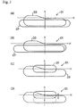
- Fig. 4 to Fig. 7 are views showing a second embodiment and a third embodiment of the head lamp 1 according to the invention, and in the invention, the second elliptic system reflecting surface 4 can be provided at a free position to the first elliptic system reflecting surface 3, as far as the reflecting surface 3 and 4 can not cause the mutual interference to such an extent as to make formation of the light-distribution characteristic impossible.
- a second embodiment shown in Fig. 4 and Fig. 5 has the constitution that the major axis Y of the second elliptic system reflecting surface 4 is set so as to direct toward the lower to the illuminating axis X (refer to Fig. 5), therefore, the parabolic system reflecting surface 7 is arranged on the lower of the first elliptic system reflecting surface 3, and a front shape of the head lamp 1 in this second embodiment has the reversed shape of the first embodiment, in which the projection lens 6 is provided on the upper and the lens 8 is provided on the lower thereof as shown in Fig. 4.
- a third embodiment shown in Fig. 6 and Fig. 7 has the constitution that the major axis Y of the second elliptic system reflecting surface 4 is set so as to direct toward the side to the illuminating axis X (refer to Fig. 7), in which the parabolic system reflecting surface 7 is arranged on the side of the first elliptic system reflecting surface 3, and a front shape of the head lamp 1 in the third embodiment has the shape that the projection lens 6 and the lens 8 are arranged horizontally as shown in Fig. 6.
- a third embodiment it is shown in the example of the case where inclining axis Z of the parabolic system reflecting surface 7 within the horizontal plane.
- the utilization factor of luminous flux to the light source 2 can be improved, and the bright head lamp not only can be realized, but also flexibility is increased, whereby conformability for a vehicle design can be improved in the appearance shape as described above.
- Fig. 8 and Fig. 9 are views showing a fourth embodiment of the head lamp 1 according to the invention, and in this fourth embodiment, the constitution is realized that a revolving axis 7a is provided on the parabolic system reflecting surface 7 to interlock this revolving axis 7a with a steering system or the like, for example, and to revolve as required, utilizing that the direction of the light-distribution characteristic D7 produced by this parabolic system reflecting surface 7 can be set freely by changing the direction of axis Z of the parabolic system reflecting surface 7 as described above in the first embodiment.
- the light-distribution characteristic D7 would illuminate the driving direction thereafter corresponding to the steering operation as shown in the drawings when the vehicle passes through a curved road, whereby the driving direction can be recognize visually easily. Moreover, the light-distribution characteristic D7 is shifted in the up-and-down direction as well as in the right and left direction as shown in Fig. 9 in the vehicle such as a motercycle or the like of which body inclines at turning when the revolving axis 7a is set obliquely in advance as shown by chain lines in Fig.
- the illuminating direction described above also can be changed by unifying the second elliptic system reflecting surface 4 and the parabolic system reflecting surface 7 to revolve these two surfaces of the reflecting surface 4 and 7 taking the light source as the center.
- a head lamp for a vehicle wherein a first elliptic system reflecting surface_having an optical axis in the illuminating direction of the head lamp and arranging a primary focus on the light source; and a second elliptic system reflecting surface arranging the primary focus on the same light source and intersecting the optical axis at approximately right angle to the optical axis of the first elliptic system reflecting surface are provided, the projection lens, corresponding to the secondary focus of the first elliptic system reflecting surface and the shield plate, as required are provided, and a parabolic system reflecting surface approximately taking the secondary focus as a focus, corresponding to the secondary focus of the second elliptic system reflecting surface and the shield plate and taking the optical axis as the approximately illuminating direction is provided, whereby the light shielded by the shield plate and the light from the light source which can not reach the reflecting surface and heretofore, has been invalid to form the light-distribution characteristic can be recovered, the utilization factor of
- the excellent effect extremely improving performances as the head lamp allowing the subsequent direction to illuminate without losing view of the front direction can be performed by revolving a portion of the reflecting surface such as the parabolic system reflecting surface, moreover, flexibility in an establishment of an vehicle's outward appearance form is increased to improve conformability with design of the vehicle and to perform the excellent effect in improvement of the fine view.
Landscapes
- Engineering & Computer Science (AREA)
- General Engineering & Computer Science (AREA)
- Non-Portable Lighting Devices Or Systems Thereof (AREA)
Applications Claiming Priority (2)
| Application Number | Priority Date | Filing Date | Title |
|---|---|---|---|
| JP2000041969 | 2000-02-18 | ||
| JP2000041969A JP3488960B2 (ja) | 2000-02-18 | 2000-02-18 | 車両用前照灯 |
Publications (2)
| Publication Number | Publication Date |
|---|---|
| EP1126210A2 true EP1126210A2 (de) | 2001-08-22 |
| EP1126210A3 EP1126210A3 (de) | 2003-01-02 |
Family
ID=18565107
Family Applications (1)
| Application Number | Title | Priority Date | Filing Date |
|---|---|---|---|
| EP01103492A Withdrawn EP1126210A3 (de) | 2000-02-18 | 2001-02-15 | Fahrzeugscheinwerfer |
Country Status (3)
| Country | Link |
|---|---|
| US (1) | US6454448B2 (de) |
| EP (1) | EP1126210A3 (de) |
| JP (1) | JP3488960B2 (de) |
Cited By (19)
| Publication number | Priority date | Publication date | Assignee | Title |
|---|---|---|---|---|
| US6543910B2 (en) | 2000-12-25 | 2003-04-08 | Stanley Electric Co., Ltd. | Vehicle light capable of changing light distribution pattern between low-beam mode and high-beam mode by movable shade and reflecting surface |
| FR2831944A1 (fr) * | 2001-11-08 | 2003-05-09 | Koito Mfg Co Ltd | Phare de vehicule et unite a lampe pour un tel phare |
| FR2849159A1 (fr) * | 2002-12-24 | 2004-06-25 | Valeo Vision | Projecteur a source lumineuse transversale pour vehicule automobile |
| FR2849158A1 (fr) * | 2002-12-20 | 2004-06-25 | Valeo Vision | Module d'eclairage pour projecteur de vehicule |
| US6796696B2 (en) | 2000-12-05 | 2004-09-28 | Stanley Electric Co., Ltd. | Vehicle light with movable reflector portion and shutter portion for selectively switching an illuminated area of light incident on a predetermined portion of the vehicle light during driving |
| EP1491816A1 (de) * | 2003-06-27 | 2004-12-29 | Valeo Vision | Kfz-Scheinwerfer mit einem Spiegel und einem optischen Umlenkelement |
| FR2856773A1 (fr) * | 2003-06-27 | 2004-12-31 | Valeo Vision | Projecteur pour vehicule automobile comportant un reflecteur et un element de deviation optique |
| EP1528312A1 (de) * | 2003-10-31 | 2005-05-04 | Valeo Vision | Beleuchtungsmodul für Kfz-Scheinwerfer |
| EP1538393A1 (de) * | 2003-12-05 | 2005-06-08 | Valeo Vision | Fahrzeugscheinwerfer mit vertikaler Ausführung |
| US6921188B2 (en) | 2002-05-13 | 2005-07-26 | Stanley Electric Co., Ltd. | Vehicle lamp and method |
| FR2866411A1 (fr) * | 2004-02-13 | 2005-08-19 | Valeo Vision | Projecteur pour vehicule automobile comportant un reflecteur et un element de deviation optique |
| FR2868511A1 (fr) * | 2004-03-31 | 2005-10-07 | Koito Mfg Co Ltd | Phare de vehicule a ampoule decalee |
| EP1544536A3 (de) * | 2003-12-17 | 2006-04-12 | Hella KGaA Hueck & Co. | Scheinwerfer für Fahzeuge |
| DE102004045963B4 (de) * | 2003-09-24 | 2007-12-13 | Koito Manufacturing Co., Ltd. | Fahrzeugscheinwerfer |
| WO2013144005A1 (en) | 2012-03-27 | 2013-10-03 | Fael S.P.A. | Rotational asymmetric para-ellipsoidal and biellipsoidal reflectors for lighting installations. |
| FR3008772A1 (fr) * | 2013-07-19 | 2015-01-23 | Koito Mfg Co Ltd | Lampe pour vehicule |
| EP2998647A4 (de) * | 2013-05-17 | 2017-04-19 | Ichikoh Industries, Ltd. | Fahrzeugscheinwerfer |
| DE102006045446B4 (de) * | 2005-09-26 | 2017-05-24 | Stanley Electric Co. Ltd. | Fahrzeugleuchte |
| WO2018207070A1 (en) * | 2017-05-08 | 2018-11-15 | Hella Saturnus Slovenija Proizvodnja Svetlobne Opreme Za Motorna In Druga Vozila, D.O.O. | Lighting device for a vehicle |
Families Citing this family (52)
| Publication number | Priority date | Publication date | Assignee | Title |
|---|---|---|---|---|
| JP2001283618A (ja) * | 2000-03-31 | 2001-10-12 | Stanley Electric Co Ltd | 車両用灯具 |
| JP4024618B2 (ja) * | 2002-08-09 | 2007-12-19 | 株式会社小糸製作所 | 車両用前照灯 |
| JP3916151B2 (ja) * | 2002-12-04 | 2007-05-16 | スタンレー電気株式会社 | 車両用前照灯 |
| DE10331349B4 (de) * | 2003-07-11 | 2009-05-28 | Daimler Ag | Kraftfahrzeugscheinwerfer |
| US7021804B2 (en) * | 2003-08-13 | 2006-04-04 | Guide Corporation | Lamp assembly with multi-stage reflector |
| EP1515368B1 (de) * | 2003-09-05 | 2019-12-25 | Nichia Corporation | Lichtausstattung |
| ITTO20030801A1 (it) * | 2003-10-14 | 2005-04-15 | Fiat Ricerche | Perfezionamenti negli apparecchi di illuminazione. |
| FR2861832B1 (fr) * | 2003-10-31 | 2006-12-15 | Valeo Vision | Projecteur pour vehicule automobile comportant une source lumineuse formee par une lampe a decharge |
| JP4536479B2 (ja) * | 2003-12-02 | 2010-09-01 | 株式会社小糸製作所 | 車両用前照灯 |
| JP4261452B2 (ja) | 2004-01-23 | 2009-04-30 | 株式会社小糸製作所 | 車両用前照灯 |
| JP4264364B2 (ja) * | 2004-01-27 | 2009-05-13 | 株式会社小糸製作所 | 車両用前照灯 |
| JP4203426B2 (ja) | 2004-02-05 | 2009-01-07 | 株式会社小糸製作所 | 車両用前照灯 |
| JP4405279B2 (ja) * | 2004-02-17 | 2010-01-27 | 市光工業株式会社 | プロジェクタ型車両用灯具 |
| JP4780809B2 (ja) * | 2004-02-27 | 2011-09-28 | スタンレー電気株式会社 | 車両用灯具 |
| JP2005251435A (ja) | 2004-03-01 | 2005-09-15 | Koito Mfg Co Ltd | 車両用前照灯 |
| JP2005251478A (ja) | 2004-03-02 | 2005-09-15 | Ichikoh Ind Ltd | ヘッドランプ |
| JP4308708B2 (ja) * | 2004-05-07 | 2009-08-05 | 株式会社小糸製作所 | 車両用前照灯 |
| JP4261448B2 (ja) | 2004-09-17 | 2009-04-30 | 株式会社小糸製作所 | 車両用前照灯 |
| JP2006156191A (ja) * | 2004-11-30 | 2006-06-15 | Koito Mfg Co Ltd | 車両用前照灯 |
| JP2006216337A (ja) * | 2005-02-02 | 2006-08-17 | Koito Mfg Co Ltd | 車両用前照灯 |
| US7416323B2 (en) * | 2005-03-15 | 2008-08-26 | Koito Manufacturing Co., Ltd. | Vehicle headlamp |
| US20060209556A1 (en) * | 2005-03-15 | 2006-09-21 | Koito Manufacturing Co., Ltd. | Vehicle lamp |
| JP4498977B2 (ja) | 2005-05-18 | 2010-07-07 | 株式会社小糸製作所 | 車両用前照灯 |
| JP2007080606A (ja) * | 2005-09-13 | 2007-03-29 | Koito Mfg Co Ltd | 車両用前照灯の灯具ユニット |
| JP4608645B2 (ja) * | 2005-09-26 | 2011-01-12 | スタンレー電気株式会社 | 車両用灯具 |
| JP4666160B2 (ja) * | 2006-02-06 | 2011-04-06 | スタンレー電気株式会社 | 車両用灯具 |
| JP4587047B2 (ja) * | 2006-04-17 | 2010-11-24 | スタンレー電気株式会社 | 車両用灯具 |
| FR2897142B1 (fr) * | 2006-02-03 | 2008-03-14 | Valeo Vision Sa | Module de projecteur lumineux a coupure pour vehicule automobile. |
| FR2901012B1 (fr) * | 2006-05-12 | 2008-07-18 | Valeo Vision Sa | Module optique de projecteur pour vehicule automobile |
| JP4606390B2 (ja) * | 2006-06-28 | 2011-01-05 | スタンレー電気株式会社 | 車両用前照灯 |
| JP4605118B2 (ja) * | 2006-07-27 | 2011-01-05 | 市光工業株式会社 | 車両用前照灯 |
| JP2008060022A (ja) | 2006-09-04 | 2008-03-13 | Koito Mfg Co Ltd | 車両用前照灯 |
| JP2008060021A (ja) | 2006-09-04 | 2008-03-13 | Koito Mfg Co Ltd | 車両用前照灯 |
| US7434972B2 (en) * | 2006-11-15 | 2008-10-14 | De Bao Technology Ltd. | Reflection module of a lamp of motor vehicle |
| US20080158900A1 (en) * | 2006-12-22 | 2008-07-03 | Johnson Controls Technology Company | Overhead console projector lamp optics |
| JP2008171743A (ja) * | 2007-01-15 | 2008-07-24 | Koito Mfg Co Ltd | 車両用前照灯 |
| FR2915789B1 (fr) * | 2007-05-04 | 2010-09-03 | Valeo Vision | Module optique pour dispositif projecteur elliptique adapte a un volume donne pour vehicule automobile |
| JP4811429B2 (ja) * | 2008-05-07 | 2011-11-09 | 市光工業株式会社 | プロジェクタ型ヘッドランプ |
| JP2009283408A (ja) * | 2008-05-26 | 2009-12-03 | Koito Mfg Co Ltd | 車両用前照灯 |
| JP5169665B2 (ja) * | 2008-09-17 | 2013-03-27 | 市光工業株式会社 | 車両用前照灯 |
| JP5157884B2 (ja) * | 2008-12-25 | 2013-03-06 | 市光工業株式会社 | 車両用前照灯 |
| JP4902675B2 (ja) * | 2009-01-09 | 2012-03-21 | 三菱電機株式会社 | 車両用前照灯 |
| JP5418760B2 (ja) * | 2009-01-28 | 2014-02-19 | スタンレー電気株式会社 | 車両用灯具 |
| JP5544248B2 (ja) * | 2010-08-24 | 2014-07-09 | 富士重工業株式会社 | 車両用前照灯 |
| JP5691514B2 (ja) * | 2010-12-28 | 2015-04-01 | スタンレー電気株式会社 | 自動二輪車用プロジェクタ型ヘッドランプ |
| JP2012185977A (ja) * | 2011-03-04 | 2012-09-27 | Honda Motor Co Ltd | 車両用ヘッドライト構造 |
| KR101460728B1 (ko) * | 2011-10-13 | 2014-11-12 | 현대모비스 주식회사 | 차량용 램프 장치. |
| JP6019644B2 (ja) * | 2012-03-19 | 2016-11-02 | 市光工業株式会社 | 車両用前照灯 |
| US9476556B2 (en) * | 2013-01-04 | 2016-10-25 | Honda Motor Co., Ltd. | Vehicle headlight assembly |
| JP6174337B2 (ja) * | 2013-02-27 | 2017-08-02 | 株式会社小糸製作所 | 車両用灯具 |
| KR101755841B1 (ko) | 2015-09-11 | 2017-07-10 | 현대자동차주식회사 | 차량용 램프 장치 |
| CN105698089B (zh) * | 2016-03-14 | 2018-06-22 | 斯比夫(西安)照明技术有限公司 | 铁路机车室外照明用高聚光型反光镜 |
Family Cites Families (9)
| Publication number | Priority date | Publication date | Assignee | Title |
|---|---|---|---|---|
| DE3525041C2 (de) * | 1985-07-13 | 1994-06-16 | Bosch Gmbh Robert | Abblendlicht-oder Nebellichtscheinwerfer für Kraftfahrzeuge |
| US4956759A (en) * | 1988-12-30 | 1990-09-11 | North American Philips Corporation | Illumination system for non-imaging reflective collector |
| JP2575236Y2 (ja) * | 1992-06-12 | 1998-06-25 | スタンレー電気株式会社 | プロジェクタ型灯具 |
| JP3226391B2 (ja) | 1993-09-08 | 2001-11-05 | 株式会社小糸製作所 | 自動車用ヘッドランプ |
| JPH09219104A (ja) | 1996-02-09 | 1997-08-19 | Stanley Electric Co Ltd | 車両用照明灯具 |
| EP0843126A3 (de) * | 1996-11-14 | 2000-04-26 | Stanley Electric Co., Ltd. | Projektions- Scheinwerfer |
| JP3005687B2 (ja) | 1998-05-28 | 2000-01-31 | スタンレー電気株式会社 | 灯 具 |
| JP2001283618A (ja) * | 2000-03-31 | 2001-10-12 | Stanley Electric Co Ltd | 車両用灯具 |
| EP1219887B1 (de) * | 2000-12-25 | 2006-09-27 | Stanley Electric Co., Ltd. | Fahrzeugscheinwerfer mit einer verstellbaren Blende und einer verstellbaren Reflektorfläche zur Erzeugung eines Abblend- und Fernlichtbündels |
-
2000
- 2000-02-18 JP JP2000041969A patent/JP3488960B2/ja not_active Expired - Fee Related
-
2001
- 2001-02-15 EP EP01103492A patent/EP1126210A3/de not_active Withdrawn
- 2001-02-16 US US09/785,545 patent/US6454448B2/en not_active Expired - Lifetime
Non-Patent Citations (1)
| Title |
|---|
| None |
Cited By (34)
| Publication number | Priority date | Publication date | Assignee | Title |
|---|---|---|---|---|
| US7044624B2 (en) | 2000-12-05 | 2006-05-16 | Stanley Electric Co., Ltd. | Vehicle light with movable reflector portion and shutter portion for selectively switching an illuminated area of light incident on a predetermined portion of the vehicle light during driving |
| US6796696B2 (en) | 2000-12-05 | 2004-09-28 | Stanley Electric Co., Ltd. | Vehicle light with movable reflector portion and shutter portion for selectively switching an illuminated area of light incident on a predetermined portion of the vehicle light during driving |
| US7008094B2 (en) | 2000-12-05 | 2006-03-07 | Stanley Electric Co., Ltd. | Vehicle light with movable reflector portion and shutter portion for selectively switching an illuminated area of light incident on a predetermined portion of the vehicle light during driving |
| US6575609B2 (en) | 2000-12-25 | 2003-06-10 | Stanley Electric Co., Ltd. | Vehicle headlight |
| US6543910B2 (en) | 2000-12-25 | 2003-04-08 | Stanley Electric Co., Ltd. | Vehicle light capable of changing light distribution pattern between low-beam mode and high-beam mode by movable shade and reflecting surface |
| FR2831944A1 (fr) * | 2001-11-08 | 2003-05-09 | Koito Mfg Co Ltd | Phare de vehicule et unite a lampe pour un tel phare |
| US6921188B2 (en) | 2002-05-13 | 2005-07-26 | Stanley Electric Co., Ltd. | Vehicle lamp and method |
| FR2849158A1 (fr) * | 2002-12-20 | 2004-06-25 | Valeo Vision | Module d'eclairage pour projecteur de vehicule |
| EP1434002A1 (de) * | 2002-12-20 | 2004-06-30 | Valeo Vision | Beleuchtungseinheit für Fahrzeugscheinwerfer |
| US6966675B2 (en) | 2002-12-20 | 2005-11-22 | Valeo Vision | Lighting module for a vehicle headlight |
| FR2849159A1 (fr) * | 2002-12-24 | 2004-06-25 | Valeo Vision | Projecteur a source lumineuse transversale pour vehicule automobile |
| EP1433999A1 (de) * | 2002-12-24 | 2004-06-30 | Valeo Vision | Kfz-Scheinwerfer mit einer querliegenden LIchtquelle |
| US7125150B2 (en) | 2002-12-24 | 2006-10-24 | Valeo Vision | Projector with transverse light source for automotive vehicle |
| EP1491816A1 (de) * | 2003-06-27 | 2004-12-29 | Valeo Vision | Kfz-Scheinwerfer mit einem Spiegel und einem optischen Umlenkelement |
| US7121705B2 (en) | 2003-06-27 | 2006-10-17 | Valeo Vision | Headlight for a motor vehicle comprising a reflector and an optical deviation element |
| EP2009347A1 (de) * | 2003-06-27 | 2008-12-31 | Valeo Vision | Kfz-Scheinwerfer mit einem Spiegel und einem optischen Umlenkelement |
| FR2856773A1 (fr) * | 2003-06-27 | 2004-12-31 | Valeo Vision | Projecteur pour vehicule automobile comportant un reflecteur et un element de deviation optique |
| DE102004045963B4 (de) * | 2003-09-24 | 2007-12-13 | Koito Manufacturing Co., Ltd. | Fahrzeugscheinwerfer |
| US7347600B2 (en) | 2003-10-31 | 2008-03-25 | Valeo Vision | Lighting module for a vehicle headlight |
| FR2861831A1 (fr) * | 2003-10-31 | 2005-05-06 | Valeo Vision | Module d'eclairage pour projecteur de vehicule |
| EP1528312A1 (de) * | 2003-10-31 | 2005-05-04 | Valeo Vision | Beleuchtungsmodul für Kfz-Scheinwerfer |
| FR2863342A1 (fr) * | 2003-12-05 | 2005-06-10 | Valeo Vision | Projecteur verticalise pour vehicule automobile |
| EP1538393A1 (de) * | 2003-12-05 | 2005-06-08 | Valeo Vision | Fahrzeugscheinwerfer mit vertikaler Ausführung |
| EP1544536A3 (de) * | 2003-12-17 | 2006-04-12 | Hella KGaA Hueck & Co. | Scheinwerfer für Fahzeuge |
| FR2866411A1 (fr) * | 2004-02-13 | 2005-08-19 | Valeo Vision | Projecteur pour vehicule automobile comportant un reflecteur et un element de deviation optique |
| FR2868511A1 (fr) * | 2004-03-31 | 2005-10-07 | Koito Mfg Co Ltd | Phare de vehicule a ampoule decalee |
| DE102006045446B4 (de) * | 2005-09-26 | 2017-05-24 | Stanley Electric Co. Ltd. | Fahrzeugleuchte |
| WO2013144005A1 (en) | 2012-03-27 | 2013-10-03 | Fael S.P.A. | Rotational asymmetric para-ellipsoidal and biellipsoidal reflectors for lighting installations. |
| EP2998647A4 (de) * | 2013-05-17 | 2017-04-19 | Ichikoh Industries, Ltd. | Fahrzeugscheinwerfer |
| US9939122B2 (en) | 2013-05-17 | 2018-04-10 | Ichikoh Industries, Ltd. | Vehicle headlamp |
| CN105229371B (zh) * | 2013-05-17 | 2018-08-24 | 市光工业株式会社 | 车辆用前照灯 |
| FR3008772A1 (fr) * | 2013-07-19 | 2015-01-23 | Koito Mfg Co Ltd | Lampe pour vehicule |
| US9772082B2 (en) | 2013-07-19 | 2017-09-26 | Koito Manufacturing Co., Ltd. | Vehicular lamp |
| WO2018207070A1 (en) * | 2017-05-08 | 2018-11-15 | Hella Saturnus Slovenija Proizvodnja Svetlobne Opreme Za Motorna In Druga Vozila, D.O.O. | Lighting device for a vehicle |
Also Published As
| Publication number | Publication date |
|---|---|
| JP2001229715A (ja) | 2001-08-24 |
| US6454448B2 (en) | 2002-09-24 |
| EP1126210A3 (de) | 2003-01-02 |
| JP3488960B2 (ja) | 2004-01-19 |
| US20010021112A1 (en) | 2001-09-13 |
Similar Documents
| Publication | Publication Date | Title |
|---|---|---|
| US6454448B2 (en) | Head lamp for vehicle | |
| US10895357B2 (en) | Vehicle lamp | |
| JP5869223B2 (ja) | 車両用前照灯 | |
| US7824086B2 (en) | Lamp unit for vehicle headlamp and vehicle headlamp | |
| CN106969311A (zh) | 车辆用灯具 | |
| US10962188B2 (en) | Vehicle lamp | |
| WO2006033042A1 (en) | Led collimator element with an asymmetrical collimator | |
| US20070064438A1 (en) | Lamp unit for a vehicle headlamp | |
| US6758589B2 (en) | Headlamp for vehicle | |
| US6471383B1 (en) | Headlamp for vehicle | |
| JP2010235108A (ja) | 車両用前照灯装置 | |
| JP3740635B2 (ja) | 車両用照明灯具 | |
| US6742920B2 (en) | Vehicle headlamp having extended illumination on both sides of a horizontal cut-line | |
| JP2023172580A (ja) | 車両用灯具 | |
| JP4382633B2 (ja) | プロジェクタ型灯具 | |
| EP1286106B1 (de) | Fahrzeugscheinwerfer | |
| US6729752B2 (en) | Headlamp | |
| JP5869807B2 (ja) | プロジェクタ型ヘッドランプ | |
| JP4009452B2 (ja) | 横長レンズプロジェクター型ヘッドランプ | |
| US20090316415A1 (en) | Lamp unit | |
| JP5755085B2 (ja) | プロジェクタ型ヘッドランプ | |
| JP2009163922A (ja) | 車両用前照灯 | |
| JP2003132712A (ja) | 車両用前照灯 | |
| JP2009187722A (ja) | 車両用灯具 | |
| JP2013052701A (ja) | プロジェクタ型ヘッドランプ |
Legal Events
| Date | Code | Title | Description |
|---|---|---|---|
| PUAI | Public reference made under article 153(3) epc to a published international application that has entered the european phase |
Free format text: ORIGINAL CODE: 0009012 |
|
| AK | Designated contracting states |
Kind code of ref document: A2 Designated state(s): AT BE CH CY DE DK ES FI FR GB GR IE IT LI LU MC NL PT SE TR |
|
| AX | Request for extension of the european patent |
Free format text: AL;LT;LV;MK;RO;SI |
|
| PUAL | Search report despatched |
Free format text: ORIGINAL CODE: 0009013 |
|
| AK | Designated contracting states |
Kind code of ref document: A3 Designated state(s): AT BE CH CY DE DK ES FI FR GB GR IE IT LI LU MC NL PT SE TR |
|
| AX | Request for extension of the european patent |
Free format text: AL;LT;LV;MK;RO;SI |
|
| AKX | Designation fees paid | ||
| REG | Reference to a national code |
Ref country code: DE Ref legal event code: 8566 |
|
| STAA | Information on the status of an ep patent application or granted ep patent |
Free format text: STATUS: THE APPLICATION IS DEEMED TO BE WITHDRAWN |
|
| 18D | Application deemed to be withdrawn |
Effective date: 20030902 |