EP1126241A2 - Gyroscope à vibration et appareil électronique comportant un tel gyroscope - Google Patents
Gyroscope à vibration et appareil électronique comportant un tel gyroscope Download PDFInfo
- Publication number
- EP1126241A2 EP1126241A2 EP01103086A EP01103086A EP1126241A2 EP 1126241 A2 EP1126241 A2 EP 1126241A2 EP 01103086 A EP01103086 A EP 01103086A EP 01103086 A EP01103086 A EP 01103086A EP 1126241 A2 EP1126241 A2 EP 1126241A2
- Authority
- EP
- European Patent Office
- Prior art keywords
- vibrator
- vibrating gyroscope
- substrate
- portions
- supporting members
- Prior art date
- Legal status (The legal status is an assumption and is not a legal conclusion. Google has not performed a legal analysis and makes no representation as to the accuracy of the status listed.)
- Granted
Links
Images


Classifications
-
- G—PHYSICS
- G01—MEASURING; TESTING
- G01C—MEASURING DISTANCES, LEVELS OR BEARINGS; SURVEYING; NAVIGATION; GYROSCOPIC INSTRUMENTS; PHOTOGRAMMETRY OR VIDEOGRAMMETRY
- G01C19/00—Gyroscopes; Turn-sensitive devices using vibrating masses; Turn-sensitive devices without moving masses; Measuring angular rate using gyroscopic effects
- G01C19/56—Turn-sensitive devices using vibrating masses, e.g. vibratory angular rate sensors based on Coriolis forces
- G01C19/5642—Turn-sensitive devices using vibrating masses, e.g. vibratory angular rate sensors based on Coriolis forces using vibrating bars or beams
- G01C19/5663—Manufacturing; Trimming; Mounting; Housings
Definitions
- the present invention relates to vibrating gyroscopes and electronic apparatuses incorporating the same, and more specifically, it relates to a vibrating gyroscope for use in video cameras with image stabilization capabilities, car navigation systems, pointing devices, etc., and to an electronic apparatus incorporating the same.
- Fig. 10 is a fragmentary perspective view of a conventional vibrating gyroscope.
- the principles of the vibrating gyroscope 80 shown in Fig. 10 are disclosed in Japanese Unexamined Patent Application Publication No. 10-332379.
- the vibrating gyroscope 80 includes a vibrator 100, supporting members 804, 805, 806, and 807, and a frame 810.
- the vibrator 100 includes a first piezoelectric substrate 101 polarized in the thickness direction, a first detecting electrode 101a and a second detecting electrode 101b being formed on a first principal plane thereof, and a second piezoelectric substrate 102 polarized in the thickness direction, a driving electrode (not shown) being formed on a first principal plane thereof.
- a second principal plane of the first piezoelectric substrate 101 and a second principal plane of the second piezoelectric substrate 102 are laminated via an intermediary electrode 103.
- the supporting members 804 and 805 are provided at the positions where node points N1 and N2 of the vibrator 100 are projected on the first principal plane of the first piezoelectric substrate 101, and the supporting members 806 and 807 are provided at the positions where the node points N1 and N2 are projected on the first principal plane of the second piezoelectric substrate 102.
- the first detecting electrode 101a is connected to the supporting member 804, the second detecting electrode 101b is connected to the supporting member 805, and the driving electrode on the first principal plane of the second piezoelectric substrate 102 is connected to the supporting members 806 and 807.
- the supporting members 804, 805, 806, and 807 are composed of the same material, are constructed in the same shape, and have the same stiffness, and support the piezoelectric substrates 101 and 102 while also serving as leads.
- the frame 810 is composed of an insulating material such as resin, and has an upper face 810a on the same plane as the first principal plane of the first piezoelectric substrate 101, a lower face 810b on the same plane as the first principal plane of the second piezoelectric substrate 102, and projections 811 provided on an inner face of the frame 810 with a particular spacing along the width direction of the vibrator 100.
- Ends 804a, 805a, 806a, and 807a of the supporting members 804, 805, 806, and 807 extend in a direction parallel to the first principal plane of the first piezoelectric substrate 101 or the first principal plane of the second piezoelectric substrate 102.
- the ends 804a and 805b are fixed to the upper face 810a of the frame 810, for example, by soldering, and the ends 806a and 807a are fixed to the lower face 810b of the frame 810, for example, by soldering.
- a vibrating gyroscope requires thick supporting members in order to prevent problems such as the vibrator falling off from the supporting members due to an excessive shock exerted on the vibrating gyroscope.
- Use of thick supporting members causes the vibration of the vibrator to leak from the supporting members, reducing the magnitude of the vibration.
- thin supporting members 804 and 806 are provided so as to sandwich the node point N1
- thin supporting members 805 and 807 are provided so as to sandwich the node point N2
- the supporting members 804, 805, 806, and 807 are fixed to the substrate 810 having the same thickness as the piezoelectric substrates 101 and 102.
- the vibrator 100 avoids problems such as falling off from the supporting members 804, 805, 806, and 807.
- the vibrating gyroscope 80 when a driving signal is applied to the driving electrode on the first principal plane of the second piezoelectric substrate 102 via the supporting members 806 and 807, longitudinal-bar flexural oscillation occurs in the thickness direction of the vibrator 100, in which the nodes in the lowest mode are the node points N1 and N2.
- an angular velocity for which the longitudinal direction of the vibrator 100 is the axis, is applied to the vibrating gyroscope 80, the vibrator 100 is flexed in the width direction, and signals output from the first detecting electrode 101a and the second detecting electrode 101b are processed, so that the angular velocity applied to the vibrating gyroscope is determined.
- the projections 811 are provided with a particular spacing along the width direction of the vibrator 100, so that excessive displacement of the vibrator 100 and plastic deformation of the supporting members 804, 805, 806, and 807 are prevented even if an excessive shock in the width direction of the vibrator 100 is exerted on the vibrating gyroscope 80.
- FIG. 11 is a fragmentary exploded perspective view of another conventional vibrating gyroscope.
- components identical to or equivalent to those in the vibrating gyroscope 80 shown in Fig. 10 are indicated by the same reference characters, and description thereof is omitted.
- a vibrating gyroscope 90 includes a frame 820 instead of the frame 810 in the vibrating gyroscope 80, a substrate 830 (not shown in Fig. 10), a lower lid 840, and an upper lid (not shown) having the same construction as the lower lid 840.
- the frame 820 is composed of resin, and includes an upper face 820a on a plane above a first principal plane of a first piezoelectric substrate 101, a lower face 820b on a plane below a first principal plane of a second piezoelectric substrate 102, and in addition, convex portions 812 provided on inner faces of the frame 820, and concave slots 813 provided on the upper face 820a and the lower face 820b of the frame 820.
- Supporting members 804 and 805 are led into the frame 820 from the top faces of the convex portions 812, supporting members 806 and 807 are led into the frame 820 from side faces of the convex portions 812, and ends 805a and 807a and ends 804a and 806a (not shown) of the supporting members 804, 805, 806, and 807 are pulled out from side faces of the convex portions 812.
- the substrate is provided with lands 831, 832, 833, and 834 formed on the top face thereof, and electronic components mounted on the bottom face thereof, necessary for driving a vibrator 100 (not shown) or for determining angular velocity.
- the substrate 830 is fixed to the frame 820 so as to engage with the bottom faces of the convex portions 812 and with the inner faces of the frame 820.
- the ends 804a, 805a, 806a, and 807a of the supporting members 804, 805, 806, and 807 are connected to the lands 831, 832, 833, and 834.
- the upper lid and the lower lid 840 are composed of resin, and are provided with third projections 841.
- the upper lid and the lower lid 840 are fixed to the frame 820 so that the third projections 841 and the concave slots 813 of the frame 820 engage with each other.
- the vibrator 100 is fixed to the frame 820 and the substrate 830 is also fixed to the frame 820, so that the vibrator 100, the frame 820, and the substrate 830 are integrated. Furthermore, the upper lid and the lower lid 840 are provided so as to seal the electronic components mounted on the substrate 830, electrically shielding the electronic components from the outside.
- thin supporting members 804, 805, 806, and 807 are provided so as to sandwich the node points N1 and N2 of the vibrator 100, and are fixed to the frame 810 having the same thickness as the piezoelectric substrates 101 and 102.
- the area of the entire vibrating gyroscope is determined in product specifications, the area of the substrate 830 is restricted and the need arises to mount the vibrator 100 and required electronic components on the top face and the bottom face of the substrate 830, causing a problem in the increased height of the overall vibrating gyroscope.
- the lower lid 840 when the electronic components are mounted on the bottom face of the substrate 130, the lower lid 840 must be provided in order to seal in the electronic components, causing the problems in the further increase height of the overall vibrating gyroscope and an increase in the number of parts.
- the manufacturing process for three-dimensionally constructing the frame 820 and the supporting members 804, 805, 806, and 807 is very complex, causing a problem of laborious production.
- a vibrating gyroscope comprises a substrate, a vibrator, and supporting members fixed in proximity to the node points on both principal planes of the vibrator.
- the supporting members comprise first portions extending in a direction parallel, to the substrate from the principal planes of the vibrator, and second portions extending in a direction orthogonal to the substrate, the second portions being fixed to the substrate.
- the vibrating gyroscope according to the present invention is also characterized in that the second portions are disposed in proximity to the vibrator, and in that the second portions inhibit excessive displacement of the vibrator when the vibrator is excessively displaced.
- the vibrating gyroscope according to the present invention is also characterized in that the second portions comprise projections, which are disposed in proximity to the vibrator and which inhibit excessive displacement of the vibrator when the vibrator is excessively displaced.
- the vibrating gyroscope according to the present invention is also characterized in that the second portions comprise bent portions bent back in a direction orthogonal to the substrate.
- the vibrating gyroscope according to the present invention is also characterized in that the supporting members are composed of a hard elastic material.
- the vibrating gyroscope according to the present invention is also characterized in that it includes driving means for vibrating the vibrator, and detecting means for detecting an output generated by the vibrator.
- the vibrating gyroscope according to the present invention is also characterized in that electronic components are mounted on the substrate only on the face on which the vibrator is mounted, and in that a case is fixed on the substrate so as to cover the vibrator and the electronic components.
- the vibrating gyroscope according to the present invention is also characterized in that the substrate comprises through holes at the ends thereof.
- An electronic apparatus is characterized by comprising the vibrating gyroscope.
- the vibrator is supported by being sandwiched from above and below the node points N1 and N2, so that the vibration of the vibrator is inhibited from leaking from the supporting members, and so that the vibrator is inhibited from falling off from the supporting members even if an excessive shock is exerted thereon.
- the second portions are provided in proximity to the vibrator, so that the supporting members are not susceptible to plastic deformation even if an excessive shock is exerted thereon.
- the vibrating gyroscope according to the present invention has a reduced number of parts because it does not include a frame.
- the vibrating gyroscope according to the present invention allows adjustment of the stiffness of the supporting members through coordination of the length of the bent portions provided in the second portions.
- the stiffness of the supporting members provided on the upper face of the vibrator and the stiffness of the supporting members provided on the lower face of the vibrator can be made equal, so that the vibrator is allowed to vibrate freely, serving to accurately determine angular velocity.
- the vibrating gyroscope according to the present invention allows the vibrator to be fixed on the substrate for integration without using any upper lid, lower lid, or frame. Therefore, because the upper lid, lower lid, and frame are not included, the size of the overall vibrating gyroscope is reduced, the height is decreased, and the number of parts is reduced.
- the vibrating gyroscope according to the present invention in which the bottom face of the substrate is not electrically connected to any electronic component, can be used as a surface-mounted component by affixing a case on the substrate and providing through holes at the ends of the substrate.
- the vibrating gyroscope according to the present invention which has a metallic case, allows it to be smaller and allows shielding of the electronic components from external electromagnetic waves.
- the vibrating gyroscope according to the present invention is smaller because no frame is included, so that the area on the substrate for mounting the components and for lands can be increased.
- the electronic apparatus according to the present invention is of reduced cost and smaller size owing to a reduction in the number of parts and smaller size of the vibrating gyroscope.
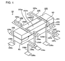
- Fig. 1 is a perspective view of an embodiment of a vibrating gyroscope according to the present invention.
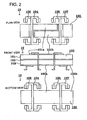
- Fig. 2 shows a plan view, front view, and bottom view of the gyroscope in Fig. 1.
- Fig. 3 is a perspective view of another embodiment of supporting members of the vibrating gyroscope in Fig. 1.
- Fig. 4 shows a plan view, front view, and bottom view of another embodiment of a vibrating gyroscope according to the present invention.
- Fig. 5 is a perspective view of another embodiment of supporting members of the vibrating gyroscope in Fig. 4.
- Fig. 6 is a perspective view of yet another embodiment of a vibrating gyroscope according to the present invention.
- Fig. 7 is a block diagram of the embodiment of a vibrating gyroscope in Fig. 6.
- Fig. 8 is a perspective view of yet another embodiment of a vibrating gyroscope according to the present invention.
- Fig. 9 is a block diagram of an embodiment of an image stabilization circuit incorporated in an electronic apparatus, according to the present invention.
- Fig. 10 is a fragmentary perspective view of a conventional vibrating gyroscope.
- Fig. 11 is a fragmentary exploded perspective view of another conventional vibrating gyroscope.
- Fig. 1 shows a perspective view of an embodiment of a vibrating gyroscope according to the present invention
- Fig. 2 shows a plan view, a front view, and a bottom view thereof.
- components which perform functions similar to those in the vibrating gyroscopes 80 and 90 shown in Figs. 10 and 11 are indicated by the same reference characters, and description thereof is omitted.
- a vibrating gyroscope 10 includes a vibrator 100, a substrate (not shown), and supporting members 104, 105, 106, and 107.
- the supporting members 104, 105, 106, and 107, respectively, are composed of a hard elastic material, such as metal, and include, on the planes where first principal planes of piezoelectric substrates 101 and 102 are formed, first portions 104a, 105a, 106a, and 107a extending in the width direction of the vibrator 100 away from the first principal planes of the piezoelectric substrates 101 and 102, and then are bent towards the vibrator 100, and second portions 104b, 105b, 106b, and 107b extending in the thickness direction of the vibrator 100 from the proximity of vibrator 100.
- the ends 104c, 105c, 106c, and 107c of the second portions 104b, 105b, 106b, and 107b are fixed to the substrate.
- a node point N1 of the vibrator 100 is supported by being sandwiched by the first portions 104a and 106a, and a node point N2 is supported by being sandwiched by the first portions 105a and 107a. Because the vibrator 100 is supported by being sandwiched by the first principal planes of the piezoelectric substrate 101 and the piezoelectric substrates 102, the vibrator 100 is not susceptible to problems such as falling off from the supporting members 104, 105, 106, and 107, without using a frame or thick supporting members, even if an excessive shock is exerted on the vibrating gyroscope 100.
- the first portions 104a, 105a, 106a, and 107a of the vibrating gyroscope 100 extend in the width direction of the vibrator 100 on planes parallel to the first principal planes of the piezoelectric substrates 101 and 102, and are then bent in an L-shape in the longitudinal direction of the vibrator 100, thereby constituting a flexible structure which does not damp the vibration of the vibrator 100 with respect to the width direction. Accordingly, the vibration of the piezoelectric substrates 101 and 102 with respect to the width direction is inhibited from leaking from the supporting members 104, 105, 106, and 107; thus, the vibration of the vibrator 100 is inhibited from being attenuated.
- the first portions 104a and 105b extend in the width direction of the vibrator 100, and then are bent back in a U-shape. If an excessive shock in the width direction of the vibrator 100 is exerted on the vibrating gyroscope 10, the vibrator 100 bumps against the second portions 104b and 105b. Accordingly, excessive displacement of the vibrator 100 and. plastic deformation of the supporting members 104, 105, 106, and 107 are prevented.
- the vibrating gyroscope 10 in which no frame is included, has a reduced number of parts.
- Fig. 3 shows a perspective view of another embodiment of supporting members in the vibrating gyroscope according to the present invention.
- Fig. 3 shows a supporting member 135 and a supporting member 136 corresponding respectively to the supporting member 105 and the supporting member 106 of the vibrating gyroscope shown in Figs. 1 and 2.
- a second portion of the supporting member 135 includes bent portions 135b' and 135b'' bent back in the thickness direction of the vibrator 100, and a supporting member 134 (not shown) corresponding to the supporting member 104 also includes similar bent portions 134b' and 134b''.
- a second portion of the supporting member 136 includes bent portions 136b' and 136b'' bent back in the thickness direction of the vibrator 100, and a supporting member 137 (not shown) corresponding to the supporting member 107 also includes similar bent portions 137b' (not shown) and 137b'' (not shown).
- the stiffness of the vibrator with respect to the thickness direction becomes smaller as the distance between the substrate and the vibrator increases. Therefore, supporting members provided on the upper face of the vibrator have a smaller stiffness than supporting members provided on the lower face of the vibrator.
- the stiffness of the supporting members varies as such depending on the distance from the substrate, the upper face and the lower face of the vibrator are supported in different conditions, inhibiting free vibration of the vibrator with respect to the thickness direction and also inhibiting accurate determination of angular velocity.
- the length of the bent portions 134b' and 134b'' and the length of the bent portions 136b' and 136b'' can be coordinated, and the length of the bent portions 135b' and 135b'' and the length of the bent portions 137b' and 137b'' can be coordinated, so that the stiffness of the vibrator 100 with respect to the thickness direction will be equivalent. Accordingly, by coordinating the bent portions as required, the supporting members 134 and 135 provided on the upper face of the vibrator 100 and the supporting members 136 and 137 provided on the lower face of the vibrator 100 can be made to have an equivalent stiffness with respect to the thickness direction of the vibrator 100.
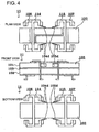
- Fig. 4 shows a plan view, a front view, and a bottom view of another embodiment of a vibrating gyroscope according to the present invention.
- components identical to or equivalent to those in the vibrating gyroscope 10 shown in Figs. 1 and 2 are indicated by the same reference characters, and description thereof is omitted.
- a vibrating gyroscope 11 includes supporting members 114 and 115 instead of the supporting members 104 and 105 of the vibrating gyroscope 10.
- the supporting members 114 and 115 includes projections 104d and 105d on second portions 114b and 115b.
- the projections 104d and 105d are provided toward the vibrator 100 with a slight tilt angle with respect to the longitudinal direction of the vibrator 100.
- the projections 104d and 105d are provided in proximity to the vibrator 100 so that when an excessive shock is exerted on the vibrator 100, the projections 104d and 105d bump against the vibrator 100 so as to inhibit excessive displacement of the vibrator 100. Furthermore, in the vibrating gyroscope 11, the spacing between the vibrator 100 and the supporting members 114 and 115 can be finely controlled by adjusting the tilt angle of the projections 104d and 105d. It is equally advantageous to provide projections only on one of the supporting members 114 and 115.
- FIG. 5 is a perspective view of yet another embodiment of supporting members in the vibrating gyroscope according to the present invention.
- Fig. 5 only shows a supporting member 124 corresponding to the supporting member 104 of the vibrating gyroscope shown in Figs. 1 and 2.
- the supporting member 124 includes projections 124d on second portions 124b away from the proximity of the vibrator 100, and a supporting member 125 (not shown) corresponding to the supporting member 105 also includes similar projections 125d (not shown). Similarly to the projections 104d and 105d, the projections 124d and 125d are provided toward the vibrator 100 with a slight tilt angle with respect to the longitudinal direction of the vibrator 100.
- the supporting member 124 When the supporting member 124 includes such projections 124d, it may be formed so that the second portion 124b is away from the proximity of the vibrator 100 while only the projection 124d is in proximity to the vibrator 100. It is equally advantageous to provide the projections 125d on the supporting member 125.
- FIG. 6 shows a perspective view of yet another embodiment of a vibrating gyroscope according to the present invention.
- components identical to or equivalent to those in the vibrating gyroscope 10 shown in Figs. 1 and 2 are indicated by the same reference characters, and description thereof is omitted.
- a vibrating gyroscope 60 includes a substrate 20 (not shown in Fig. 1), electronic components 30, and a case 40.
- the substrate 20 has through holes 21 at the ends thereof, and a vibrator 100 and the electronic components are mounted only on the top face thereof.
- the electronic components 30 are required for driving the vibrator 100 or for determining angular velocity.
- the case 40 is fixed on the top face of the substrate 20 so as to cover the vibrator 100 and the electronic components 30.
- the supporting members 104, 105, 106, and 107 are used instead of using an upper lid, a lower lid, and a frame, in order to affix the vibrator 100 to the substrate 20 integrally, and the substrate 20 and the case 40 seal the electronic components 30 so as to electrically shield the electronic components 30 from the outside. Furthermore, because no upper lid, lower lid, and frame is included, the overall size of the vibrating gyroscope 60 is reduced, the height is decreased, and the number of parts is reduced.
- the vibrator 100 and the electronic components 30 are mounted only on the top face of the substrate 20, and the bottom face of the substrate 20 is not electrically connected to the electronic components 30.
- the vibrating gyroscope 60 by providing the through holes 21 at the ends of the substrate 20, can be used as a surface-mounted component which is directly mountable on an external circuit pattern.
- the case 40 of the vibrating gyroscope 60 is a metallic case, it is thinner than a resin case; thus, it serves to reduce the overall size of the vibrating gyroscope 60 while also shielding the electronic components 30 from external electromagnetic waves. Furthermore, by making the case 40 thinner, the case occupies a smaller area on the substrate 20, allowing for a larger area for mounting the components and for the lands.
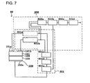
- Fig. 7 shows a block diagram of a vibrating gyroscope according to the present invention.
- Fig. 7 is a block diagram of the vibrating gyroscope 60 shown in Fig. 6, incorporating the electronic components 30, and includes an oscillation circuit 601 as a driving means, and a detection circuit 602 as a detecting means.
- the oscillation circuit 60 includes a first charge amplifier601a, second charge amplifier601b, an adder circuit 601c, an AGC circuit 601d, and a phase compensation circuit 601e
- the detecting circuit 602 includes the first charge amplifier601a, the second charge amplifier601b, a differential circuit 602a, a detector circuit 602b, a smoothing circuit 602c, and an amplifier circuit 602d.
- a first detecting electrode 101a of the vibrator 100 is connected to the first charge amplifier601a, and a second detecting electrode 101b is connected to the second charge amplifier601b.
- the first charge amplifier601a and the second charge amplifier601b are respectively connected to the adder circuit 601c and to the differential circuit 602a.
- the adder circuit 601c is connected to the AGC circuit 601d, the AGC circuit 601d is connected to the phase compensation circuit 601e, and the phase compensation circuit 601e is connected to the detector circuit 602b and to a driving electrode 102a.
- the differential circuit 602a is connected to the detector circuit 602b, the detector circuit 602b is connected to the smoothing circuit 602c, and the smoothing circuit 602c is connected to the amplifier circuit 602d.
- the first charge amplifier601a converts the charge generated at the detecting electrode 101a into a voltage and outputs to the adder circuit 601c and to the differential circuit 602a
- the second charge amplifier601b converts the charge generated at the second detecting electrode 101b into a voltage and outputs to the adder circuit 601c and to the differential circuit 602a.
- the adder circuit 601c takes the sum of the input signals and outputs to the AGC circuit 601d, the AGC circuit 601d amplifies the input signal to a constant amplitude and outputs to the phase compensation circuit 601e, and the phase compensation circuit 601e compensates the phase of the input signal and applies a driving signal to the driving electrode 102a.
- the differential circuit 602a takes the difference of the input signals and outputs to the detector circuit 602b, the detector circuit 602b detects, in accordance with the signals input from the phase compensation circuit 601e, the signal input from the differential circuit 602a, and outputs to the smoothing circuit 602c, and the amplifier circuit 602d DC-amplifies the input signal outputs to the outside.
- the vibrator 100 when the driving signal is applied to the driving electrode 102a, the vibrator 100 causes a longitudinal-bar flexural oscillation in the thickness direction, in which the nodes in the lowest mode are node points N1 and N2.
- an angular velocity for which the longitudinal direction is the axis, is applied to the vibrator 100, a flexural displacement is generated in the width direction due to the Coriolis force, so that the angular velocity is determined based on the difference between the signals from the first detecting electrode 101a and from the second detecting electrode 101b.
- a signal is detected which corresponds to a flexural displacement in the width direction of the vibrator 100, which is not influenced by the Coriolis force.
- the vibrating gyroscope according to the present invention internally having the oscillation circuit 601 and the detection circuit 602 required for determining angular velocity, serves to constitute an integrated vibrating gyroscope unit.
- FIG. 8 shows yet another embodiment of a vibrating gyroscope according to the present invention.
- components identical to or equivalent to those in the vibrating gyroscope 60 shown in Fig. 7 are indicated by the same reference characters, and description thereof is omitted.
- a vibrating gyroscope 61 includes an oscillation circuit 611 and a detection circuit 612 instead of the oscillation circuit 601 and the detection circuit 602 of the vibrating gyroscope 60 shown in Fig. 7.
- the oscillation circuit 611 and the detection circuit 612 only differ from the oscillation circuit 601 and the detection circuit 602 in that resistors 611a and 611b, a first buffer circuit 611c, and a second buffer circuit 611d are included instead of the first charge amplifier601a and the second charge amplifier601b shown in Fig. 8.
- the resistor 611a and the first buffer circuit 611c are connected to a first detecting electrode 101a, and the resistor 611b and the second buffer circuit 611d are connected to a second detecting electrode 101b.
- the first buffer circuit 611c and the second buffer circuit 611d are connected to an adder circuit 601c and a differential circuit 602a.
- the first buffer circuit 611c is provided for outputting a voltage at the first detecting electrode 101a to the adder circuit 601c and the differential circuit 602a
- the second buffer circuit is provided for outputting a voltage at the second detecting electrode 101b to the adder circuit 601c and the differential circuit 602a
- the resistors 611a and 611b are provided for adjusting the impedance of the first detecting electrode 101a and the second detecting electrode 101b.
- the vibrating gyroscope 61 according to the present invention so constructed is equally advantageous as the vibrating gyroscope 60 shown in Fig. 7.
- FIG. 9 shows an embodiment of an electronic apparatus incorporating a vibrating gyroscope according to the present invention.
- Fig. 9 is a block diagram of an image stabilization circuit incorporated in a video camera as the electronic apparatus according to the present invention.
- An image stabilization circuit 70 includes a vibrating gyroscope 10 according to the present invention, an integrator circuit 701, a servo circuit 702, a current driver 703, an actuator 704, and a position sensor 705.
- the vibrating gyroscope 10 the integrator circuit 701, the servo circuit 702, the current driver 703, and the actuator 704 are connected in series, and the output of the actuator 704 is fed back to the servo circuit 702 via the position sensor 705.
- the image stabilization circuit 70 so constructed, with regard to shaking exerted on the video camera, only the angular velocity signal is input from the vibrating gyroscope 10 to the integrator circuit 701, the integrator circuit 701 integrates the angular velocity signal, converts into an angle of deviation of the video camera, and outputs to the servo circuit 702, the servo circuit 702 uses deviation angle signals input from the integrator circuit 701 and from the position sensor 705 to calculate the difference between the current value and the target value, and outputs to the current driver 703, the current driver 703 outputs to the actuator 704 a current in accordance with the input signal, and the actuator 704 mechanically drives an optical system of the video camera.
- the position sensor 705 outputs to the servo circuit 702 the deviation angle due to the movement of the optical system.
- the video camera incorporating the image stabilization circuit 70 so constructed having the vibrating gyroscope which allows accurate determination of angular velocity, accurately compensates for the effects of shaking exerted on the video camera.
Landscapes
- Engineering & Computer Science (AREA)
- Physics & Mathematics (AREA)
- General Physics & Mathematics (AREA)
- Radar, Positioning & Navigation (AREA)
- Remote Sensing (AREA)
- Manufacturing & Machinery (AREA)
- Gyroscopes (AREA)
Applications Claiming Priority (2)
| Application Number | Priority Date | Filing Date | Title |
|---|---|---|---|
| JP2000036886 | 2000-02-15 | ||
| JP2000036886A JP3674440B2 (ja) | 2000-02-15 | 2000-02-15 | 振動ジャイロ |
Publications (3)
| Publication Number | Publication Date |
|---|---|
| EP1126241A2 true EP1126241A2 (fr) | 2001-08-22 |
| EP1126241A3 EP1126241A3 (fr) | 2003-12-17 |
| EP1126241B1 EP1126241B1 (fr) | 2005-10-26 |
Family
ID=18560860
Family Applications (1)
| Application Number | Title | Priority Date | Filing Date |
|---|---|---|---|
| EP01103086A Expired - Lifetime EP1126241B1 (fr) | 2000-02-15 | 2001-02-09 | Gyroscope à vibration et appareil électronique comportant un tel gyroscope |
Country Status (5)
| Country | Link |
|---|---|
| US (1) | US6532816B2 (fr) |
| EP (1) | EP1126241B1 (fr) |
| JP (1) | JP3674440B2 (fr) |
| KR (1) | KR100406126B1 (fr) |
| DE (1) | DE60114261D1 (fr) |
Cited By (1)
| Publication number | Priority date | Publication date | Assignee | Title |
|---|---|---|---|---|
| US6898973B2 (en) | 2001-11-29 | 2005-05-31 | Murata Manufacturing Co., Ltd. | Vibrating gyroscope and electronic device including same |
Families Citing this family (12)
| Publication number | Priority date | Publication date | Assignee | Title |
|---|---|---|---|---|
| JP3613117B2 (ja) * | 2000-02-23 | 2005-01-26 | 株式会社村田製作所 | 振動子及びそれを用いた振動ジャイロ及びそれを用いた電子装置 |
| JP2002228449A (ja) * | 2001-01-29 | 2002-08-14 | Murata Mfg Co Ltd | 振動ジャイロの製造方法 |
| JP2002250630A (ja) * | 2001-02-26 | 2002-09-06 | Murata Mfg Co Ltd | 振動子支持構造およびそれを用いた振動ジャイロおよびそれを用いた電子装置 |
| JP3687609B2 (ja) * | 2001-04-19 | 2005-08-24 | 株式会社村田製作所 | 振動ジャイロおよびそれを用いた電子装置 |
| JP3741041B2 (ja) * | 2001-05-09 | 2006-02-01 | 株式会社村田製作所 | 振動ジャイロおよびそれを用いた電子装置 |
| JP3687619B2 (ja) | 2002-03-25 | 2005-08-24 | 株式会社村田製作所 | 振動ジャイロおよびそれを用いた電子装置 |
| JP4497345B2 (ja) | 2003-02-12 | 2010-07-07 | 株式会社村田製作所 | 振動子の支持構造及び該支持構造の製造方法 |
| JP2005114631A (ja) * | 2003-10-09 | 2005-04-28 | Sony Corp | 角速度センサ |
| JP2006029901A (ja) * | 2004-07-14 | 2006-02-02 | Sony Corp | 振動ジャイロの駆動回路 |
| KR100828184B1 (ko) * | 2006-10-19 | 2008-05-08 | 한국과학기술원 | 기계적 가변 이득 증폭기 |
| JP5845672B2 (ja) | 2011-07-13 | 2016-01-20 | セイコーエプソン株式会社 | センサーデバイスおよび電子機器 |
| WO2019044697A1 (fr) * | 2017-08-29 | 2019-03-07 | 京セラ株式会社 | Élément de capteur et capteur de vitesse angulaire |
Family Cites Families (10)
| Publication number | Priority date | Publication date | Assignee | Title |
|---|---|---|---|---|
| US5874674A (en) * | 1988-08-12 | 1999-02-23 | Murata Manufacturing Co., Ltd. | Vibrator including piezoelectric electrodes or detectors arranged to be non-parallel and non-perpendicular to coriolis force direction and vibratory gyroscope using the same |
| JPH06123634A (ja) * | 1992-08-31 | 1994-05-06 | Murata Mfg Co Ltd | 振動ジャイロ |
| JP3211562B2 (ja) * | 1994-05-12 | 2001-09-25 | 株式会社村田製作所 | 圧電振動子 |
| US5794080A (en) * | 1994-08-31 | 1998-08-11 | Nikon Corporation | Piezoelectric vibration angular velocity meter and camera using the same |
| JPH08178671A (ja) | 1994-12-27 | 1996-07-12 | Tokin Corp | 圧電振動ジャイロ |
| JP3000888B2 (ja) * | 1995-06-07 | 2000-01-17 | 株式会社村田製作所 | 振動ジャイロ |
| JPH09105639A (ja) * | 1995-08-08 | 1997-04-22 | Murata Mfg Co Ltd | 振動ジャイロおよびその製造方法 |
| JPH09159455A (ja) | 1995-12-04 | 1997-06-20 | Akai Electric Co Ltd | 振動子の保護構造 |
| JP3082663B2 (ja) * | 1996-04-04 | 2000-08-28 | 株式会社村田製作所 | 振動ジャイロ |
| JP3286902B2 (ja) | 1997-05-28 | 2002-05-27 | 株式会社村田製作所 | 振動子の支持構造 |
-
2000
- 2000-02-15 JP JP2000036886A patent/JP3674440B2/ja not_active Expired - Lifetime
-
2001
- 2001-02-08 US US09/779,264 patent/US6532816B2/en not_active Expired - Lifetime
- 2001-02-09 DE DE60114261T patent/DE60114261D1/de not_active Expired - Lifetime
- 2001-02-09 EP EP01103086A patent/EP1126241B1/fr not_active Expired - Lifetime
- 2001-02-13 KR KR10-2001-0006961A patent/KR100406126B1/ko not_active Expired - Lifetime
Cited By (2)
| Publication number | Priority date | Publication date | Assignee | Title |
|---|---|---|---|---|
| US6898973B2 (en) | 2001-11-29 | 2005-05-31 | Murata Manufacturing Co., Ltd. | Vibrating gyroscope and electronic device including same |
| DE10255609B4 (de) * | 2001-11-29 | 2006-05-18 | Murata Manufacturing Co., Ltd., Nagaokakyo | Vibrationsgyroskop |
Also Published As
| Publication number | Publication date |
|---|---|
| DE60114261D1 (de) | 2005-12-01 |
| EP1126241B1 (fr) | 2005-10-26 |
| JP2001227953A (ja) | 2001-08-24 |
| JP3674440B2 (ja) | 2005-07-20 |
| US20010013251A1 (en) | 2001-08-16 |
| US6532816B2 (en) | 2003-03-18 |
| KR100406126B1 (ko) | 2003-11-15 |
| KR20010082158A (ko) | 2001-08-29 |
| EP1126241A3 (fr) | 2003-12-17 |
Similar Documents
| Publication | Publication Date | Title |
|---|---|---|
| EP1126241B1 (fr) | Gyroscope à vibration et appareil électronique comportant un tel gyroscope | |
| US6796177B2 (en) | Gyroscopic apparatus and electronic apparatus including same | |
| US6023973A (en) | Vibrating gyroscope and adjusting method therefor | |
| US5668316A (en) | Vibrating gyroscope | |
| CN101308022B (zh) | 检测装置、检测方法和电子装置 | |
| US6194817B1 (en) | Tuning-fork vibratory gyro | |
| JP3698094B2 (ja) | 振動ジャイロおよびそれを用いた電子装置 | |
| JPH08159806A (ja) | 方位センサおよび方位距離センサ | |
| US5349261A (en) | Vibrator | |
| US6668649B2 (en) | Vibrator for a vibrating gyroscope, vibrating gyroscope using the vibrator, and electronic apparatus using the vibrating gyroscope | |
| JP3741041B2 (ja) | 振動ジャイロおよびそれを用いた電子装置 | |
| US6822375B2 (en) | Vibrating gyroscope and electronic device using the same having a driving circuit, a detection circuit and four supporting members with different rigidities, different shapes, different cross sections, different materials and different lengths | |
| JPH05107623A (ja) | 振れ検知装置用取付装置 | |
| US5635641A (en) | Vibratory gyroscope with reduced stress and stable characteristics | |
| JP2006145420A (ja) | 角速度検出装置 | |
| US6369946B1 (en) | Image stabilizing apparatus | |
| JP2003107549A (ja) | 振動検出手段の実装装置及び防振システム | |
| EP1182426A1 (fr) | Gyroscope à vibration | |
| EP0664439A1 (fr) | Gyroscope vibrant | |
| EP1813913A2 (fr) | Système de traitement du signal du capteur et détecteur | |
| JPH08327653A (ja) | 加速度センサ | |
| JPH02163611A (ja) | 角速度計 | |
| JP3228089B2 (ja) | 加速度センサの支持構造 | |
| JP2006208131A (ja) | 振動体及びこれを備えた角速度検出装置 |
Legal Events
| Date | Code | Title | Description |
|---|---|---|---|
| PUAI | Public reference made under article 153(3) epc to a published international application that has entered the european phase |
Free format text: ORIGINAL CODE: 0009012 |
|
| 17P | Request for examination filed |
Effective date: 20010209 |
|
| AK | Designated contracting states |
Kind code of ref document: A2 Designated state(s): AT BE CH CY DE DK ES FI FR GB GR IE IT LI LU MC NL PT SE TR |
|
| AX | Request for extension of the european patent |
Free format text: AL;LT;LV;MK;RO;SI |
|
| PUAL | Search report despatched |
Free format text: ORIGINAL CODE: 0009013 |
|
| AK | Designated contracting states |
Kind code of ref document: A3 Designated state(s): AT BE CH CY DE DK ES FI FR GB GR IE IT LI LU MC NL PT SE TR |
|
| AX | Request for extension of the european patent |
Extension state: AL LT LV MK RO SI |
|
| RIC1 | Information provided on ipc code assigned before grant |
Ipc: 7G 01P 9/04 B Ipc: 7G 01C 19/56 A |
|
| 17Q | First examination report despatched |
Effective date: 20040331 |
|
| AKX | Designation fees paid |
Designated state(s): DE FR GB |
|
| GRAP | Despatch of communication of intention to grant a patent |
Free format text: ORIGINAL CODE: EPIDOSNIGR1 |
|
| GRAS | Grant fee paid |
Free format text: ORIGINAL CODE: EPIDOSNIGR3 |
|
| GRAA | (expected) grant |
Free format text: ORIGINAL CODE: 0009210 |
|
| AK | Designated contracting states |
Kind code of ref document: B1 Designated state(s): DE FR GB |
|
| REG | Reference to a national code |
Ref country code: GB Ref legal event code: FG4D |
|
| REF | Corresponds to: |
Ref document number: 60114261 Country of ref document: DE Date of ref document: 20051201 Kind code of ref document: P |
|
| PG25 | Lapsed in a contracting state [announced via postgrant information from national office to epo] |
Ref country code: DE Free format text: LAPSE BECAUSE OF FAILURE TO SUBMIT A TRANSLATION OF THE DESCRIPTION OR TO PAY THE FEE WITHIN THE PRESCRIBED TIME-LIMIT Effective date: 20060127 |
|
| PLBE | No opposition filed within time limit |
Free format text: ORIGINAL CODE: 0009261 |
|
| STAA | Information on the status of an ep patent application or granted ep patent |
Free format text: STATUS: NO OPPOSITION FILED WITHIN TIME LIMIT |
|
| 26N | No opposition filed |
Effective date: 20060727 |
|
| EN | Fr: translation not filed | ||
| PG25 | Lapsed in a contracting state [announced via postgrant information from national office to epo] |
Ref country code: FR Free format text: LAPSE BECAUSE OF FAILURE TO SUBMIT A TRANSLATION OF THE DESCRIPTION OR TO PAY THE FEE WITHIN THE PRESCRIBED TIME-LIMIT Effective date: 20061215 |
|
| PG25 | Lapsed in a contracting state [announced via postgrant information from national office to epo] |
Ref country code: FR Free format text: LAPSE BECAUSE OF FAILURE TO SUBMIT A TRANSLATION OF THE DESCRIPTION OR TO PAY THE FEE WITHIN THE PRESCRIBED TIME-LIMIT Effective date: 20060228 |
|
| PG25 | Lapsed in a contracting state [announced via postgrant information from national office to epo] |
Ref country code: FR Free format text: LAPSE BECAUSE OF FAILURE TO SUBMIT A TRANSLATION OF THE DESCRIPTION OR TO PAY THE FEE WITHIN THE PRESCRIBED TIME-LIMIT Effective date: 20051026 |
|
| PGFP | Annual fee paid to national office [announced via postgrant information from national office to epo] |
Ref country code: GB Payment date: 20200219 Year of fee payment: 20 |
|
| REG | Reference to a national code |
Ref country code: GB Ref legal event code: PE20 Expiry date: 20210208 |
|
| PG25 | Lapsed in a contracting state [announced via postgrant information from national office to epo] |
Ref country code: GB Free format text: LAPSE BECAUSE OF EXPIRATION OF PROTECTION Effective date: 20210208 |