EP1126257A2 - Vorrichtung zur Selektion und Detektion mindestens eines Spektralbereichs eines spektral aufgefächerten Lichtstrahls - Google Patents
Vorrichtung zur Selektion und Detektion mindestens eines Spektralbereichs eines spektral aufgefächerten Lichtstrahls Download PDFInfo
- Publication number
- EP1126257A2 EP1126257A2 EP01102621A EP01102621A EP1126257A2 EP 1126257 A2 EP1126257 A2 EP 1126257A2 EP 01102621 A EP01102621 A EP 01102621A EP 01102621 A EP01102621 A EP 01102621A EP 1126257 A2 EP1126257 A2 EP 1126257A2
- Authority
- EP
- European Patent Office
- Prior art keywords
- optical component
- focal line
- detector
- light beam
- optical
- Prior art date
- Legal status (The legal status is an assumption and is not a legal conclusion. Google has not performed a legal analysis and makes no representation as to the accuracy of the status listed.)
- Granted
Links
Images


Classifications
-
- G—PHYSICS
- G02—OPTICS
- G02B—OPTICAL ELEMENTS, SYSTEMS OR APPARATUS
- G02B21/00—Microscopes
- G02B21/0004—Microscopes specially adapted for specific applications
- G02B21/002—Scanning microscopes
- G02B21/0024—Confocal scanning microscopes (CSOMs) or confocal "macroscopes"; Accessories which are not restricted to use with CSOMs, e.g. sample holders
- G02B21/0052—Optical details of the image generation
- G02B21/0064—Optical details of the image generation multi-spectral or wavelength-selective arrangements, e.g. wavelength fan-out, chromatic profiling
-
- G—PHYSICS
- G01—MEASURING; TESTING
- G01J—MEASUREMENT OF INTENSITY, VELOCITY, SPECTRAL CONTENT, POLARISATION, PHASE OR PULSE CHARACTERISTICS OF INFRARED, VISIBLE OR ULTRAVIOLET LIGHT; COLORIMETRY; RADIATION PYROMETRY
- G01J3/00—Spectrometry; Spectrophotometry; Monochromators; Measuring colours
- G01J3/28—Investigating the spectrum
- G01J3/30—Measuring the intensity of spectral lines directly on the spectrum itself
- G01J3/32—Investigating bands of a spectrum in sequence by a single detector
Definitions
- the present invention relates at least to a device for selection and detection a spectral range of a spectrally fanned light beam, preferably in the Beam path of a confocal scanning microscope, the fanned out light beam in a focal line is focusable.
- Devices of the generic type are from DE 43 30 347 and DE 199 02 625 known. These devices are preferably confocal in the beam path Laser scanning microscopes are used. In doing so, a detection pinhole is passed Beam of light spectrally fanned out with a dispersive optical component. Part of the spectrally fanned out light beam can then be a first variably arranged Pass mirror aperture arrangement. The corresponding spectral range is then from detected by a detector. The proportion of the fanned light beam that is on the first If the mirror diaphragm arrangement hits, it becomes a further mirror diaphragm arrangement reflected. A part of the original can also be on the other mirror aperture arrangement reflected spectrally fanned light beam pass through with another detector is detected. The remaining part is closed with the further mirror aperture device reflected by a third detector.
- the cascaded Detector arrangement further refocusing the selected Spectral range necessary, otherwise the optical paths of the divergent Light beam can no longer be imaged on a detector with a limited area.
- the fault tolerance is the Positioning of the optical components of the previously known devices their cascaded arrangement extremely small.
- the misalignment affects a first mirror diaphragm arranged in the spectrally fanned out light beam has a negative effect all of its detectors, which reduces their detection efficiency.
- the invention is therefore based on the object of a device for selection and Detection of at least one spectral range of a spectrally fanned light beam, preferably in the beam path of a confocal scanning microscope and to further develop that in the selection of the spectrally fanned light beam selected spectral ranges do not overlap.
- the Fault tolerance regarding the arrangement of the optical components can be increased.
- the device of the generic type according to the invention solves the foregoing Object by the features of claim 1.
- the optically effective area decreases or increases along the surface, so that by aligning the component to the focal line and the resulting overlap the spectral range of the focal line and surface can be defined.
- a cascaded arrangement of the optical components can be done in the manner according to the invention due to the special orientation of a reflective and / or refractive optical Component are waived.
- This optical component becomes spectral relative to the focal line fanned out light beam arranged and aligned so that only the out spectral result of the overlap of the focal line and surface of the optical component Area to the detector is reflected and / or broken.
- Cascading several Optical components arranged one behind the other can thereby be avoided, as a result in an advantageous manner on an additional focusing of the reflected or refracted Light beam can be dispensed with.
- the optical component is designed in such a way that its optically effective area is different reduced or enlarged along its surface. This is the corresponding Alignment of the optical component relative to the focal line of the optical component reflected or refracted portion of the spectrally fanned light can be reduced or expandable.
- the device according to the invention it is possible to carry out the spectral selection with the help of reflective and / or refractive optical components directly in the focal line perform so that the above-mentioned spectral overlap, which is already in the closer Environment around the focal line occurs can be avoided in an advantageous manner.
- the surface of the optical component is in its Area of overlap with the focal line always arranged tangentially to the focal line.
- the focal line of the spectrally fanned out light beam is always on the Surface of the optical component.
- This arrangement of the optical component is one Spectrally sharp detection ensured, as it is always in a range of the spectral fanned out light beam is selected in which the spectral ranges are not overlap.
- the optical component is arranged to be movable allow variable selection of the spectral range.
- the movement of the optical component could take place in one direction, so that the effective area of the optical component relative to the focal line changes, which changes the spectral range reaching the detector is enlarged or reduced.
- This allows in advantageously the starting and ending wavelength are changed, that is, the width of the Spectral range that reaches the detector assigned to the optical component.
- the optical component could be moved in a direction parallel to the focal line, whereby the spectral range reaching the detector can be changed. Through this Movement can change the selected spectral range with the same width become. Ultimately, the start and end wavelength of the spectral range can can be varied, the difference from end wavelength to start wavelength, i.e. the spectral width, remains constant. To optimize the detected signal yield provided that when the optical component moves in a to the focal line parallel direction of the detector assigned to the optical component in the same way is moved.
- the movement of the optical component takes place in a particularly advantageous manner along a direction in which the effective area of the optical component is relative to the Focal line changed, as well as in a direction parallel to the focal line. This is the Width as well as the start and end wavelength of the spectral range to be detected definable, which opens up particularly flexible application options.
- the optical components are arranged such that they are in the place of Touch the focal line. This arrangement enables a complete detection of the spectral fanned out light beam with several detectors.
- the light running in this space would thus not be assigned to a detector, so the corresponding spectral range is not is detected.
- Excitation wavelength of a laser light source is provided because only the fluorescent light is of interest or is detected.
- the light running in a space could be detected by a detector which is assigned to this intermediate space.
- This Measure could above all facilitate the spatial arrangement of several detectors, especially when the optical components used are reflective.
- the detector assigned to an intermediate space could thus go beyond the focal line in Direction of propagation of the spectrally fanned light beam may be arranged, whereas the detectors assigned to the reflected optical components in the direction of the reflected light can be arranged.
- the arrangement of the detectors compared to the extent of the focal line are large, this can result in a large Solid angle range.
- the optical components from both sides of the Fan level can be introduced. This would be a grouping of several juxtaposed optical components conceivable from one side of the Fanning plane are arranged and aligned. Another grouping Accordingly, several optical components arranged side by side could differ from the other side of the fan-out plane, so that the optical components one side of the fanning-out plane cover a possibly continuous spectral range can. In an alternative embodiment, an alternating arrangement of the optical components provided so that along the focal line an optical component from the one side of the fan-out plane is arranged, which is adjacent to an optical component which is arranged from the other side of the fan-out plane.
- the optical component has a flat surface.
- the surface of the optical component has tapered edges. The this would then define a surface shape, for example, a trapezoid correspond.
- the edges of the optical component could be at an edge intersection meet, whereby the surface of the optical component have the shape of a triangle would.
- the optical components can be moved in this way arranged that the edge intersections of several optical arranged side by side
- components essentially meet at one point. From this Basic setting could then be the successive arrangement of the individual optical Components are made relative to the focal line.
- the movement of an optical component can Movement of other optical components due to space constraints.
- a wedge, a pyramid, a tetrahedron or a could be used as the shape of an optical component Obelisk may be provided.
- the use of different optical components Shapes would also be conceivable.
- the optical component could be designed as a prism or as a light collector that on light striking its surface refracts.
- a prism or as a light collector that on light striking its surface refracts.
- the shape of the prism as well as its Refractive index chosen such that the refraction of the incident on its surface Light takes place as efficiently as possible, i.e. has minimal reflection.
- a light collector could serve, for example, a funnel-shaped plexiglass block, in general it can these are light guides.
- the light refracted by the prism or the light collector is due to total internal reflection directed to the detector.
- the detector can directly with the optical component be operatively connected so that the broken light is detected immediately can.
- the optical component has at least partially mirrored outer surfaces.
- the optical component is designed as a mirror that reflects the light hitting its surface.
- the mirror could, for example, from one consist of wedge-shaped component, on the surface of which a mirror layer is applied. If the surface of the mirror is flat, the component moves relative to the focal line always in a direction that lies in the plane of the mirror surface.
- the mirror has a cylindrical surface.
- the optical component could have the shape of an obliquely cut circular cylinder or have a cylinder section.
- the corresponding cylinder jacket section is provided with a reflective surface so that the optically effective area this cylinder jacket section is reduced or enlarged along its surface is trained.
- the cylindrical optical components are guided on an axis that is parallel to the Focal line is arranged.
- This guide axis coincides with the axis of an obliquely cut one Circular cylinder or a cylinder section together.
- the distance one The guide axis of the cylindrical optical components to the focal line corresponds to the radius of the cylindrical optical components. This ensures that the cylindrical Surface of the optical component in its area of overlap with the focal line always are arranged tangentially to the focal line.
- the Spectrum range reaching detector By rotating a cylindrical optical component around its axis, the Spectrum range reaching detector can be enlarged or reduced. If that cylindrical optical components are moved along the direction of its guide axis, can the spectral range reaching the detector with the same spectral width to be changed.
- a superposition of both forms of movement of a cylindrical optical component - i.e. the rotation around its axis and the movement along the Direction of its axis - allows flexible selection of a spectral range, so that in principle, its width and its position along the focal line can be freely adjusted is.
- the Surface normals of the various optical components at the location of the focal line in show different directions. This is especially true when using as Optical components made of mirrors relevant. In this case it is an optical one Component-assigned detector in the direction of the main beam of the reflected light arranged. This makes it possible to arrange a large number of detectors because due to the orientation of the surface normal of the individual optical components the entire solid angle range across the focal line is available.
- the axes When using cylindrical optical components, there are the number of used Guide axes indicate the different directions of the possible surface normals. Conveniently, the axes could be at different distances from the Focal line are arranged, i.e. the cylinder surfaces of the components are different Axes have a different radius of curvature. In addition, could go along the focal line the cylindrical optical components of different guide axes be arranged side by side. In this case, the detectors are immediately adjacent cylindrical optical components arranged in different directions, so that due to clever arrangement of the cylindrical optical components, the use of many is also possible Detectors is possible.
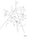
- FIG. 1 shows a device for selection and detection of at least one Spectral range of a spectrally fanned light beam 1 in the beam path of a confocal scanning microscope, the fanned out light beam 1 in a focal line 2 is focusable.
- the light beam to a detector 3 is in the fanned out light beam 1 reflective and / or refractive optical component 4 arranged, the optical effective area 4a decreases or increases along the surface 4b, so that by aligning the component 4 to the focal line 2 and the resulting line Coverage of focal line 2 and surface of the one reaching detector 3 Spectral range 5 is definable. 1 can also be seen that the incident light beam 6 spectrally from a prism 7 arranged in the beam path 6 is disassembled.
- the optical component 4 is arranged such that its surface 4b in the region of the Overlap with the focal line 2 is always tangential to the focal line 2.
- the optical component 4 is movably arranged.
- the movement of the optical component 4 can take place either along a direction 8 or along a direction 9. If that optical component 4 is moved along the direction 8, the effective area changes of the optical component 4 relative to the focal line 2. This makes the detector 3 spectral range 5 is enlarged or reduced. If the optical component 4 in a direction 9 parallel to the focal line 2 can be moved to the detector 3 spectral region 5 that arrives at a constant width with regard to its initial or End point to be changed.
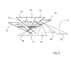
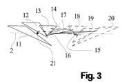
- FIGS. 2 and 3 An alternative embodiment of the device according to the invention is FIGS. 2 and 3 removable.
- a plurality of optical components 12, 13, 14 and 15 are arranged such that they touch each other at the focal line 2.
- the effective area 12a, 13a, 14a, 15a of the optical components 12, 13, 14 and 15 a complete detection of the spectrally fanned light beam 1 possible. They touch in the same way Optical components 16, 17, 18, 19 and 20 shown in dashed lines, so that this too corresponding spectral range of the focal line 2 can be detected without gaps.
- Between the optical component 11 with its effective area 11a and optical component 12 is a Intermediate space 21 is provided which does not reflect or reflect from an optical component is broken.
- the spectrally fanned light beam 1 and the focal line 2 span the Fan-out level 10 on.
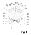
- the schematic side view from FIG. 4 can be seen that the optical components 11 to 15 from one side of the fan-out plane 10 are introduced, the optical components 16 to 20 from the other side of the Fan level 10 are introduced. 4, only the surfaces of the optical components 11 to 20 indicated, thus in the side view as a route are drawn.
- the optical components 11 to 20 from FIGS. 2, 3 and 4 have one flat surface.
- the optical component 4 has a triangular surface 4b.
- FIGS. 5, 6 and 7 show the embodiment of FIGS. 2, 3 and 4 in another Adjustment of the optical components 11 to 20.
- FIGS. 5 and 7 can be seen that the edge intersections of a plurality of optical components 11 arranged next to one another, 12, 13, 14, 15 and 16, 17, 18, 19, 20 are essentially in a basic setting hit a point 25.
- Point 25 lies on the focus line 2, so in this case no part of the spectrally fanned out light beam 1 to one of the optical components 11 to 20 assigned detectors arrives.
- This basic setting is in this Embodiment used for spectral calibration of components 11 to 20.
- the shape of the optical components 11 to 20 is designed as a wedge, in FIGS. 2 to 7 however, only the surfaces of the individual wedge-shaped optical components drawn.
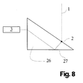
- FIG. 8 An alternative exemplary embodiment is shown in FIG. 8.
- the optical component is here designed as a prism 26.
- the light 1 striking its surface is emitted by the Prism 26 broken.
- the mirrored outer surface 27 By totally internal reflection on the mirrored outer surface 27 the light thus refracted is directed to the detector 3 assigned to the prism 26.
- 9 is a side view of an embodiment with several pyramidal prisms.
- FIG. 10 shows a light collector 26 made of plexiglass, which is directly connected to it associated detector 3 is connected. This also applies to the light collector 26 Light striking the surface is refracted and due to total internal reflection to the detector 3 headed.
- optical components 11 to 20 are designed as mirrors, which light striking its surface to the detectors 28 to 37 assigned to it reflect. This can be seen in FIG. 4.
- FIG. 11 shows a top view of an alternative exemplary embodiment.
- the optical components 38 to 43 designed as a mirror that has a cylindrical surface exhibit.
- the optical components 38 to 43 are cylinder sections, whose cylinder section jacket is provided with a mirrored surface.
- the optical component 38 is in the schematic three-dimensional view of FIG. 12 shown.
- the cylinder section is only an oblique on both sides cut cylinder segment.
- the Cylinder section on two flat surfaces, each at an angle ⁇ of 10 ° to Symmetry surface 44 and run in a common distance, also in the Symmetry surface 44, meet.
- the mirrored surface 45 of the cylinder section 38 has in the symmetry surface 44 on the radius 46.
- a Fastening means 49 is provided, which has a guide bore 50.
- the entire Component 49, 38 is rotatable and not displaceable relative to the guide bore 50 arranged in Fig. 12 axis 47.
- cylindrical optical components 38, 40 and 42 are on the axis 47 are guided.
- the cylindrical optical components 39, 41 and 43 are open the guide axis 48 out.
- the cylindrical optical components can with respect their axes 47 and 48 are rotated in the directions 51, which leads to the detector spectral range can be enlarged or reduced. Beyond that the cylindrical optical components along the direction 9 of their guide axis 47 or 48 or can be moved parallel to the focus line 2, as a result of which the one reaching the detector Spectral range can be changed with the same width.
Landscapes
- Physics & Mathematics (AREA)
- Spectroscopy & Molecular Physics (AREA)
- General Physics & Mathematics (AREA)
- Chemical & Material Sciences (AREA)
- Analytical Chemistry (AREA)
- Optics & Photonics (AREA)
- Microscoopes, Condenser (AREA)
- Spectrometry And Color Measurement (AREA)
- Investigating Or Analysing Materials By Optical Means (AREA)
Abstract
Description
- Fig. 1
- eine schematische dreidimensionale Darstellung einer erfindungsgemäßen Ausführungsform,
- Fig. 2
- eine Draufsicht einer schematischen Darstellung eines alternativen erfindungsgemäßen Ausführungsbeispiels,
- Fig. 3
- eine schematische Seitenansicht des Ausführungsbeispiels aus der Fig. 2,
- Fig. 4
- eine schematische Seitenansicht zu dem Ausführungsbeispiel aus den Fig. 2 und 3,
- Fig. 5
- eine schematische Draufsicht des Ausführungsbeispiels aus der Fig. 2, bei dem die einzelnen optischen Bauteile unterschiedlich angeordnet sind,
- Fig. 6
- eine schematische Seitenansicht des Ausführungsbeispiels aus der Fig. 5,
- Fig. 7
- eine schematische Seitenansicht des Ausführungsbeispiels aus den Fig. 5 und Fig. 6,
- Fig. 8
- eine schematische Darstellung eines alternativen Ausführungsbeispiels der erfindungsgemäßen Vorrichtung,
- Fig. 9
- eine schematische Seitenansicht eines konkreten Ausführungsbeispiels gemäß Fig. 8,
- Fig. 10
- in einer schematischen dreidimensionalen Ansicht ein alternatives Ausführungsbeispiel der erfindungsgemäßen Vorrichtung,
- Fig. 11
- in einer schematischen Darstellung die Draufsicht eines weiteren Ausführungsbeispiels der erfindungsgemäßen Vorrichtung und
- Fig. 12
- eine schematische dreidimensionale Seitenansicht eines optischen Bauteils aus der Fig. 11.
- 1
- spektral aufgefächerter Lichtstrahl
- 2
- Fokallinie
- 3
- Detektor
- 4
- optisches Bauteil
- 4a
- Wirksamer Bereich
- 4b
- Oberfläche
- 5
- Spektralbereich
- 6
- einfallender Lichtstrahl
- 7
- Prisma
- 8
- Bewegungsrichtung quer zu (2)
- 9
- Bewegungsrichtung entlang (2)
- 10
- Auffächerungsebene
- 11-20
- optische Bauteile
- 11a-15a
- wirksame Bereiche
- 21
- Zwischenraum zwischen (11) und (12)
- 22
- Kante von (4)
- 23
- Kante von (4)
- 24
- Kantenschnittpunkt von (22) und (23)
- 25
- Treffpunkt der (24) von (11) bis (20)
- 26
- Prisma, Lichtsammler
- 27
- verspiegelte Fläche von (26)
- 28-37
- Detektoren von (11) bis (20)
- 38-43
- Spiegel mit zylindrischer Oberfläche
- 44
- Symmetriefläche von (38)
- 45
- verspiegelte Oberfläche von (38)
- 46
- Radius von (45) in (44)
- 47
- Achse von (38), (40) und (42)
- 48
- Achse von (39), (41) und (43)
- 49
- Befestigungsmittel von (38)
- 50
- Führungsbohrung
- 51
- Drehrichtung von (40) bis (43)
Claims (15)
- Vorrichtung zur Selektion und Detektion mindestens eines Spektralbereichs eines spektral aufgefächerten Lichtstrahls (1), vorzugsweise im Strahlengang eines konfokalen Rastermikroskops, wobei der aufgefächerte Lichtstrahl (1) in einer Fokallinie (2) fokussierbar ist,
dadurch gekennzeichnet, dass im aufgefächerten Lichtstrahl (1) mindestens ein den Lichtstrahl zu einem Detektor (3) reflektierendes und/oder brechendes optisches Bauteil (4) angeordnet ist, dessen optisch wirksamer Bereich (4a) sich entlang der Oberfläche verkleinert oder vergrößert, so dass durch Ausrichtung des Bauteils (4) zur Fokallinie (2) und die sich daraus ergebende Überdeckung von Fokallinie (2) und Oberfläche (4b) der zum Detektor (3) gelangende Spektralbereich (5) definierbar ist. - Vorrichtung nach Anspruch 1, dadurch gekennzeichnet, dass die Oberfläche (4b) des optischen Bauteils (4) in ihrem Bereich der Überdeckung mit der Fokallinie (2) stets tangential zur Fokallinie (2) angeordnet ist.
- Vorrichtung nach Anspruch 1 oder 2, dadurch gekennzeichnet, dass das optische Bauteil (4) beweglich angeordnet ist.
- Vorrichtung nach Anspruch 3, dadurch gekennzeichnet, dass die Bewegung des optischen Bauteils (4) entlang einer Richtung (8) erfolgt, so dass sich der wirksame Bereich (4a) des optischen Bauteils (4) relativ zur Fokallinie (2) verändert, wodurch sich der zum Detektor (3) gelangende Spektralbereich (5) vergrößert oder verkleinert.
- Vorrichtung nach Anspruch 3 oder 4, dadurch gekennzeichnet, dass das optische Bauteil (4) in einer zur Fokallinie (2) parallelen Richtung (9) bewegbar ist, wodurch der zum Detektor (3) gelangende Spektralbereich (5) veränderbar ist.
- Vorrichtung nach Anspruch 5, dadurch gekennzeichnet, dass bei einer Bewegung des optischen Bauteils (4) in einer zur Fokallinie (2) parallelen Richtung (9) der dem optischen Bauteil (4) zugeordnete Detektor (3) in gleicher Weise bewegt wird.
- Vorrichtung nach einem der Ansprüche 1 bis 6, dadurch gekennzeichnet, dass mehrere optische Bauteile (12, 13, 14, 15) derart angeordnet sind, dass sie sich an der Stelle der Fokallinie (2) berühren, so dass eine lückenlose Detektion des spektral aufgefächerten Lichtstrahls (1) möglich ist.
- Vorrichtung nach einem der Ansprüche 1 bis 6, dadurch gekennzeichnet, dass entlang der Fokallinie (2) zwischen zwei optischen Bauteilen (11, 12) ein Zwischenraum (21) verbleibt.
- Vorrichtung nach einem der Ansprüche 1 bis 8, dadurch gekennzeichnet, dass die Kanten (22, 23) des optischen Bauteils (4) verjüngend ausgebildet sind.
- Vorrichtung nach Anspruch 9, dadurch gekennzeichnet, dass das optische Bauteil (4) eine dreieckige Oberfläche aufweist.
- Vorrichtung nach einem der Ansprüche 1 bis 12, dadurch gekennzeichnet, dass das optische Bauteil (4) als Prisma oder als Lichtsammler ausgeführt ist, das das auf seine Oberfläche auftreffende Licht bricht.
- Vorrichtung nach Anspruch 11, dadurch gekennzeichnet, dass das vom Prisma (26) oder Lichtsammler gebrochene Licht durch total interne Reflexion zu einem Detektor (3) geleitet wird.
- Vorrichtung nach Anspruch 1, dadurch gekennzeichnet, dass das optische Bauteil (4) eine zylindrische Oberfläche aufweist.
- Vorrichtung nach einem der Ansprüche 1 bis 13, dadurch gekennzeichnet, dass die Oberflächennormalen verschiedener optischer Bauteile (11, 12, 13, 14, 15; 16, 17, 18, 19, 20) am Ort der Fokallinie (2) in unterschiedliche Richtungen zeigen.
- Vorrichtung nach einem der Ansprüche 1 bis 14, dadurch gekennzeichnet, dass die Detektion mehrerer Detektoren (28, 29, 30, 31, 32, 33, 34, 35, 36, 37) simultan erfolgt.
Applications Claiming Priority (3)
| Application Number | Priority Date | Filing Date | Title |
|---|---|---|---|
| DE10006800A DE10006800A1 (de) | 2000-02-15 | 2000-02-15 | Vorrichtung zur Selektion und Detektion mindestens eines Spektralbereichs eines spektral aufgefächerten Lichtstrahls |
| DE10006800 | 2000-02-15 | ||
| US09/783,220 US6483103B2 (en) | 2000-02-15 | 2001-02-15 | Apparatus for selecting and detecting at least one spectral region of a spectrally spread light beam |
Publications (3)
| Publication Number | Publication Date |
|---|---|
| EP1126257A2 true EP1126257A2 (de) | 2001-08-22 |
| EP1126257A3 EP1126257A3 (de) | 2003-10-29 |
| EP1126257B1 EP1126257B1 (de) | 2005-11-09 |
Family
ID=26004347
Family Applications (1)
| Application Number | Title | Priority Date | Filing Date |
|---|---|---|---|
| EP01102621A Expired - Lifetime EP1126257B1 (de) | 2000-02-15 | 2001-02-07 | Vorrichtung zur Selektion und Detektion mindestens eines Spektralbereichs eines spektral aufgefächerten Lichtstrahls |
Country Status (4)
| Country | Link |
|---|---|
| US (1) | US6483103B2 (de) |
| EP (1) | EP1126257B1 (de) |
| JP (1) | JP2001272275A (de) |
| DE (1) | DE10006800A1 (de) |
Cited By (1)
| Publication number | Priority date | Publication date | Assignee | Title |
|---|---|---|---|---|
| EP2395380A1 (de) * | 2010-06-09 | 2011-12-14 | Olympus Corporation | Abtastmikroskop |
Families Citing this family (17)
| Publication number | Priority date | Publication date | Assignee | Title |
|---|---|---|---|---|
| DE10038049A1 (de) * | 2000-08-02 | 2002-02-14 | Leica Microsystems | Optische Anordnung zur Selektion und Detektion des Spektalbereichs eines Lichtstrahls |
| DE10156695B4 (de) * | 2001-11-17 | 2004-07-15 | Leica Microsystems Heidelberg Gmbh | Scanmikroskop, Verfahren zur Scanmikroskopie und Bandpassfilter |
| DE10206979A1 (de) * | 2002-02-20 | 2003-08-21 | Leica Microsystems | Verfahren zum Benutzertraining für ein Scanmikroskop, Scanmikroskop und Software zum Benutzertraining für ein Scanmikroskop |
| DE10218706B4 (de) | 2002-04-26 | 2008-02-28 | Leica Microsystems Cms Gmbh | Verfahren zur zeitoptimierten Erfassung von speziellen Spektren mit einem Scanmikroskop |
| DE10227111B4 (de) * | 2002-06-17 | 2007-09-27 | Leica Microsystems Cms Gmbh | Spektralmikroskop und Verfahren zur Datenaufnahme mit einem Spektralmikroskop |
| DE10238100A1 (de) * | 2002-08-21 | 2004-03-04 | Leica Microsystems Heidelberg Gmbh | Vorrichtung zur spektralen Selektion und Detektion eines Lichtstrahls und Scanmikroskop |
| GB0221014D0 (en) * | 2002-09-11 | 2002-10-23 | Medical Res Council | Spectral discrimination apparatus and method |
| DE10317669B4 (de) | 2003-04-17 | 2017-03-09 | Leica Microsystems Cms Gmbh | Verfahren zur Separierung von Detektionskanälen eines mikroskopischen Systems |
| DE10339311B4 (de) | 2003-08-27 | 2006-04-27 | Leica Microsystems Cms Gmbh | System und Verfahren zur Einstellung eines Fluoreszenzspektralmesssystems zur Mikroskopie |
| DE10339312A1 (de) | 2003-08-27 | 2005-03-31 | Leica Microsystems Heidelberg Gmbh | Verfahren zur Trennung von Fluoreszenzspektren von in einer Probe vorhandenen Farbstoffen |
| DE10355150B4 (de) | 2003-11-26 | 2021-01-14 | Leica Microsystems Cms Gmbh | Verfahren und System zur Analyse von Co-Lokalisationen |
| JP4434882B2 (ja) | 2004-08-27 | 2010-03-17 | オリンパス株式会社 | レーザ走査型蛍光観察装置 |
| WO2006078857A2 (en) * | 2005-01-16 | 2006-07-27 | Baer Stephen C | Single wavelength stimulated emission depletion microscopy |
| US7397561B2 (en) * | 2005-11-07 | 2008-07-08 | Wafermasters, Incorporated | Spectroscopy system |
| CN101900656A (zh) * | 2009-05-27 | 2010-12-01 | 鸿富锦精密工业(深圳)有限公司 | 耐磨性能测试装置 |
| JP5583515B2 (ja) * | 2010-08-11 | 2014-09-03 | オリンパス株式会社 | レーザ顕微鏡用照明装置およびレーザ顕微鏡 |
| DE102016120308A1 (de) | 2016-10-25 | 2018-04-26 | Carl Zeiss Microscopy Gmbh | Optische Anordnung, Multispot-Scanning-Mikroskop und Verfahren zum Betreiben eines Mikroskops |
Family Cites Families (9)
| Publication number | Priority date | Publication date | Assignee | Title |
|---|---|---|---|---|
| DE505397C (de) * | 1929-03-13 | 1930-08-18 | Zeiss Carl Fa | Verfahren und Vorrichtung zur Erzeugung von Optimalfarben |
| CA2084923A1 (en) * | 1991-12-20 | 1993-06-21 | Ronald E. Stafford | Slm spectrometer |
| DE4330347C2 (de) * | 1993-09-08 | 1998-04-09 | Leica Lasertechnik | Verwendung einer Vorrichtung zur Selektion und Detektion mindestens zweier Spektralbereiche eines Lichtstrahls |
| US5886784A (en) | 1993-09-08 | 1999-03-23 | Leica Lasertechink Gmbh | Device for the selection and detection of at least two spectral regions in a beam of light |
| JP3137020B2 (ja) * | 1997-02-14 | 2001-02-19 | 日本電気株式会社 | 分光計 |
| DE19902625A1 (de) * | 1998-01-28 | 1999-09-30 | Leica Microsystems | Vorrichtung zur gleichzeitigen Detektion mehrerer Spektralbereiche eines Lichtstrahls |
| DE19842288A1 (de) * | 1998-08-04 | 2000-02-10 | Zeiss Carl Jena Gmbh | Einstellbare Einkopplung und/oder Detektion einer oder mehrerer Wellenlängen in einem Mikroskop |
| DE19835072A1 (de) * | 1998-08-04 | 2000-02-10 | Zeiss Carl Jena Gmbh | Anordnung zur Beleuchtung und/oder Detektion in einem Mikroskop |
| JP2000199855A (ja) * | 1998-11-02 | 2000-07-18 | Olympus Optical Co Ltd | 走査型光学顕微鏡装置 |
-
2000
- 2000-02-15 DE DE10006800A patent/DE10006800A1/de not_active Withdrawn
-
2001
- 2001-02-07 EP EP01102621A patent/EP1126257B1/de not_active Expired - Lifetime
- 2001-02-15 US US09/783,220 patent/US6483103B2/en not_active Expired - Lifetime
- 2001-02-15 JP JP2001039146A patent/JP2001272275A/ja active Pending
Cited By (2)
| Publication number | Priority date | Publication date | Assignee | Title |
|---|---|---|---|---|
| EP2395380A1 (de) * | 2010-06-09 | 2011-12-14 | Olympus Corporation | Abtastmikroskop |
| US8530824B2 (en) | 2010-06-09 | 2013-09-10 | Olympus Corporation | Scanning microscope |
Also Published As
| Publication number | Publication date |
|---|---|
| JP2001272275A (ja) | 2001-10-05 |
| EP1126257B1 (de) | 2005-11-09 |
| EP1126257A3 (de) | 2003-10-29 |
| US20020109079A1 (en) | 2002-08-15 |
| DE10006800A1 (de) | 2001-08-16 |
| US6483103B2 (en) | 2002-11-19 |
Similar Documents
| Publication | Publication Date | Title |
|---|---|---|
| EP1126257B1 (de) | Vorrichtung zur Selektion und Detektion mindestens eines Spektralbereichs eines spektral aufgefächerten Lichtstrahls | |
| EP1053497B1 (de) | Vorrichtung zur gleichzeitigen detektion mehrerer spektralbereiche eines lichtstrahls | |
| EP2948810B1 (de) | Lichtmikroskop und mikroskopieverfahren | |
| EP1006382B1 (de) | Anordnung und Vorrichtung zur optischen Strahltransformation | |
| EP3132299B1 (de) | Lichtrastermikroskop mit vereinfachter optik, insbesondere mit veränderlicher pupillenlage | |
| EP1423746B1 (de) | Mikroskop | |
| EP3218757B1 (de) | Mikroskop mit geringem verzeichnungsfehler | |
| DE10004191A1 (de) | Hochleistungs-Grossfeld-Rastermikroskop | |
| DE102010063938A1 (de) | Optisches System zur Strahlformung eines Laserstrahls sowie Lasersystem mit einem solchen optischen System | |
| EP1359452B1 (de) | Konfokales Mikroskop mit zwei Mikrolinsenarrays und einem Lochblendenarray | |
| EP1591825B2 (de) | Vorrichtung zur Einkopplung von Licht in einen Strahlengang eines Mikroskops | |
| EP2399158B1 (de) | Vorrichtung zur homogenisierung von laserstrahlung | |
| DE102017109645A1 (de) | Lichtmikroskop und Verfahren zum Bereitstellen von strukturiertem Beleuchtungslicht | |
| DE102008041062A1 (de) | Meßvorrichtung und Verfahren zum Vermessen einer Oberfläche | |
| DE102014017002A1 (de) | Laser-Scanning-Mikroskop | |
| DE102014110606A1 (de) | Mikroskop mit einer Strahlteileranordnung | |
| DE102009058244A1 (de) | Vorrichtung für die Untersuchung eines Gegenstands, vorzugsweise eines Wertdokuments, unter Verwendung optischer Strahlung | |
| EP3864446B1 (de) | Bandpassfilter für licht mit variabler unterer und oberer grenzwellenlänge | |
| DE102004034967A1 (de) | Beleuchtungsvorrichtung für ein Lichtrastermikroskop mit punktförmiger Lichtquellenverteilung | |
| DE102017129096B4 (de) | Verfahren zur spektralen Aufspaltung eines Lichtstrahls und Fluoreszenzlichtmikroskop zur Durchführung eines solchen Verfahrens | |
| DE102022117536A1 (de) | Vorrichtung zur chromatisch konfokalen Messung von Abständen | |
| EP2023182A1 (de) | Prismengelenk | |
| EP1189090B1 (de) | Optische Anordnung zum Beleuchten von Objekten | |
| DE102013114748B4 (de) | Pumpoptk mit erhöhter Zahl an Durchgängen | |
| DE102011114754A1 (de) | "Laser-Scanning-Mikroskop" |
Legal Events
| Date | Code | Title | Description |
|---|---|---|---|
| PUAI | Public reference made under article 153(3) epc to a published international application that has entered the european phase |
Free format text: ORIGINAL CODE: 0009012 |
|
| AK | Designated contracting states |
Kind code of ref document: A2 Designated state(s): AT BE CH CY DE DK ES FI FR GB GR IE IT LI LU MC NL PT SE TR |
|
| AX | Request for extension of the european patent |
Free format text: AL;LT;LV;MK;RO;SI |
|
| PUAL | Search report despatched |
Free format text: ORIGINAL CODE: 0009013 |
|
| AK | Designated contracting states |
Kind code of ref document: A3 Designated state(s): AT BE CH CY DE DK ES FI FR GB GR IE IT LI LU MC NL PT SE TR |
|
| AX | Request for extension of the european patent |
Extension state: AL LT LV MK RO SI |
|
| RIC1 | Information provided on ipc code assigned before grant |
Ipc: 7G 01J 3/36 B Ipc: 7G 02B 21/00 B Ipc: 7G 01J 3/32 A Ipc: 7G 01J 3/457 B |
|
| 17P | Request for examination filed |
Effective date: 20040416 |
|
| 17Q | First examination report despatched |
Effective date: 20040528 |
|
| AKX | Designation fees paid |
Designated state(s): DE FR GB |
|
| GRAP | Despatch of communication of intention to grant a patent |
Free format text: ORIGINAL CODE: EPIDOSNIGR1 |
|
| GRAS | Grant fee paid |
Free format text: ORIGINAL CODE: EPIDOSNIGR3 |
|
| GRAA | (expected) grant |
Free format text: ORIGINAL CODE: 0009210 |
|
| RAP1 | Party data changed (applicant data changed or rights of an application transferred) |
Owner name: LEICA MICROSYSTEMS CMS GMBH |
|
| AK | Designated contracting states |
Kind code of ref document: B1 Designated state(s): DE FR GB |
|
| REG | Reference to a national code |
Ref country code: GB Ref legal event code: FG4D Free format text: NOT ENGLISH |
|
| REF | Corresponds to: |
Ref document number: 50107940 Country of ref document: DE Date of ref document: 20051215 Kind code of ref document: P |
|
| RAP2 | Party data changed (patent owner data changed or rights of a patent transferred) |
Owner name: LEICA MICROSYSTEMS CMS GMBH |
|
| GBT | Gb: translation of ep patent filed (gb section 77(6)(a)/1977) |
Effective date: 20060108 |
|
| PLBE | No opposition filed within time limit |
Free format text: ORIGINAL CODE: 0009261 |
|
| STAA | Information on the status of an ep patent application or granted ep patent |
Free format text: STATUS: NO OPPOSITION FILED WITHIN TIME LIMIT |
|
| 26N | No opposition filed |
Effective date: 20060810 |
|
| PG25 | Lapsed in a contracting state [announced via postgrant information from national office to epo] |
Ref country code: FR Free format text: LAPSE BECAUSE OF FAILURE TO SUBMIT A TRANSLATION OF THE DESCRIPTION OR TO PAY THE FEE WITHIN THE PRESCRIBED TIME-LIMIT Effective date: 20061020 |
|
| EN | Fr: translation not filed | ||
| PG25 | Lapsed in a contracting state [announced via postgrant information from national office to epo] |
Ref country code: FR Free format text: LAPSE BECAUSE OF FAILURE TO SUBMIT A TRANSLATION OF THE DESCRIPTION OR TO PAY THE FEE WITHIN THE PRESCRIBED TIME-LIMIT Effective date: 20051109 |
|
| PGFP | Annual fee paid to national office [announced via postgrant information from national office to epo] |
Ref country code: DE Payment date: 20160218 Year of fee payment: 16 |
|
| PGFP | Annual fee paid to national office [announced via postgrant information from national office to epo] |
Ref country code: GB Payment date: 20160217 Year of fee payment: 16 |
|
| REG | Reference to a national code |
Ref country code: DE Ref legal event code: R119 Ref document number: 50107940 Country of ref document: DE |
|
| GBPC | Gb: european patent ceased through non-payment of renewal fee |
Effective date: 20170207 |
|
| PG25 | Lapsed in a contracting state [announced via postgrant information from national office to epo] |
Ref country code: DE Free format text: LAPSE BECAUSE OF NON-PAYMENT OF DUE FEES Effective date: 20170901 |
|
| PG25 | Lapsed in a contracting state [announced via postgrant information from national office to epo] |
Ref country code: GB Free format text: LAPSE BECAUSE OF NON-PAYMENT OF DUE FEES Effective date: 20170207 |