EP1126274A2 - Balayeur avec tête de mesure intérieure et courroie de poussière et de transmission combinée - Google Patents
Balayeur avec tête de mesure intérieure et courroie de poussière et de transmission combinée Download PDFInfo
- Publication number
- EP1126274A2 EP1126274A2 EP01101087A EP01101087A EP1126274A2 EP 1126274 A2 EP1126274 A2 EP 1126274A2 EP 01101087 A EP01101087 A EP 01101087A EP 01101087 A EP01101087 A EP 01101087A EP 1126274 A2 EP1126274 A2 EP 1126274A2
- Authority
- EP
- European Patent Office
- Prior art keywords
- sheet
- scanner
- gauging head
- gauging
- slot
- Prior art date
- Legal status (The legal status is an assumption and is not a legal conclusion. Google has not performed a legal analysis and makes no representation as to the accuracy of the status listed.)
- Withdrawn
Links
- 239000000428 dust Substances 0.000 title claims abstract description 7
- 239000000463 material Substances 0.000 claims abstract description 10
- 238000001816 cooling Methods 0.000 claims description 4
- 238000007789 sealing Methods 0.000 claims description 3
- 238000004891 communication Methods 0.000 claims description 2
- 239000011810 insulating material Substances 0.000 claims description 2
- 239000003570 air Substances 0.000 description 9
- 238000005259 measurement Methods 0.000 description 6
- XLYOFNOQVPJJNP-UHFFFAOYSA-N water Substances O XLYOFNOQVPJJNP-UHFFFAOYSA-N 0.000 description 3
- 238000010276 construction Methods 0.000 description 2
- 239000000498 cooling water Substances 0.000 description 2
- 238000009434 installation Methods 0.000 description 2
- 238000000034 method Methods 0.000 description 2
- 230000005855 radiation Effects 0.000 description 2
- 239000010935 stainless steel Substances 0.000 description 2
- 229910001220 stainless steel Inorganic materials 0.000 description 2
- 229910052773 Promethium Inorganic materials 0.000 description 1
- XAGFODPZIPBFFR-UHFFFAOYSA-N aluminium Chemical compound [Al] XAGFODPZIPBFFR-UHFFFAOYSA-N 0.000 description 1
- 229910052782 aluminium Inorganic materials 0.000 description 1
- 239000012080 ambient air Substances 0.000 description 1
- 230000009286 beneficial effect Effects 0.000 description 1
- 230000005494 condensation Effects 0.000 description 1
- 238000009833 condensation Methods 0.000 description 1
- 238000011109 contamination Methods 0.000 description 1
- 229920002457 flexible plastic Polymers 0.000 description 1
- VQMWBBYLQSCNPO-UHFFFAOYSA-N promethium atom Chemical compound [Pm] VQMWBBYLQSCNPO-UHFFFAOYSA-N 0.000 description 1
- 229910052704 radon Inorganic materials 0.000 description 1
- SYUHGPGVQRZVTB-UHFFFAOYSA-N radon atom Chemical compound [Rn] SYUHGPGVQRZVTB-UHFFFAOYSA-N 0.000 description 1
Images


Classifications
-
- G—PHYSICS
- G01—MEASURING; TESTING
- G01N—INVESTIGATING OR ANALYSING MATERIALS BY DETERMINING THEIR CHEMICAL OR PHYSICAL PROPERTIES
- G01N21/00—Investigating or analysing materials by the use of optical means, i.e. using sub-millimetre waves, infrared, visible or ultraviolet light
- G01N21/01—Arrangements or apparatus for facilitating the optical investigation
- G01N21/15—Preventing contamination of the components of the optical system or obstruction of the light path
-
- G—PHYSICS
- G01—MEASURING; TESTING
- G01N—INVESTIGATING OR ANALYSING MATERIALS BY DETERMINING THEIR CHEMICAL OR PHYSICAL PROPERTIES
- G01N21/00—Investigating or analysing materials by the use of optical means, i.e. using sub-millimetre waves, infrared, visible or ultraviolet light
- G01N21/17—Systems in which incident light is modified in accordance with the properties of the material investigated
- G01N21/25—Colour; Spectral properties, i.e. comparison of effect of material on the light at two or more different wavelengths or wavelength bands
- G01N21/31—Investigating relative effect of material at wavelengths characteristic of specific elements or molecules, e.g. atomic absorption spectrometry
- G01N21/35—Investigating relative effect of material at wavelengths characteristic of specific elements or molecules, e.g. atomic absorption spectrometry using infrared light
- G01N21/3554—Investigating relative effect of material at wavelengths characteristic of specific elements or molecules, e.g. atomic absorption spectrometry using infrared light for determining moisture content
-
- G—PHYSICS
- G01—MEASURING; TESTING
- G01N—INVESTIGATING OR ANALYSING MATERIALS BY DETERMINING THEIR CHEMICAL OR PHYSICAL PROPERTIES
- G01N21/00—Investigating or analysing materials by the use of optical means, i.e. using sub-millimetre waves, infrared, visible or ultraviolet light
- G01N21/84—Systems specially adapted for particular applications
- G01N21/88—Investigating the presence of flaws or contamination
- G01N21/89—Investigating the presence of flaws or contamination in moving material, e.g. running paper or textiles
-
- G—PHYSICS
- G01—MEASURING; TESTING
- G01N—INVESTIGATING OR ANALYSING MATERIALS BY DETERMINING THEIR CHEMICAL OR PHYSICAL PROPERTIES
- G01N21/00—Investigating or analysing materials by the use of optical means, i.e. using sub-millimetre waves, infrared, visible or ultraviolet light
- G01N21/84—Systems specially adapted for particular applications
- G01N21/88—Investigating the presence of flaws or contamination
- G01N21/89—Investigating the presence of flaws or contamination in moving material, e.g. running paper or textiles
- G01N21/8901—Optical details; Scanning details
-
- G—PHYSICS
- G01—MEASURING; TESTING
- G01N—INVESTIGATING OR ANALYSING MATERIALS BY DETERMINING THEIR CHEMICAL OR PHYSICAL PROPERTIES
- G01N21/00—Investigating or analysing materials by the use of optical means, i.e. using sub-millimetre waves, infrared, visible or ultraviolet light
- G01N21/17—Systems in which incident light is modified in accordance with the properties of the material investigated
- G01N21/25—Colour; Spectral properties, i.e. comparison of effect of material on the light at two or more different wavelengths or wavelength bands
- G01N21/31—Investigating relative effect of material at wavelengths characteristic of specific elements or molecules, e.g. atomic absorption spectrometry
- G01N21/35—Investigating relative effect of material at wavelengths characteristic of specific elements or molecules, e.g. atomic absorption spectrometry using infrared light
- G01N21/3554—Investigating relative effect of material at wavelengths characteristic of specific elements or molecules, e.g. atomic absorption spectrometry using infrared light for determining moisture content
- G01N21/3559—Investigating relative effect of material at wavelengths characteristic of specific elements or molecules, e.g. atomic absorption spectrometry using infrared light for determining moisture content in sheets, e.g. in paper
Definitions
- the present invention is directed to a scanner for measuring at least one parameter of a sheet material such as the basis weight or moisture content of paper and, more specifically, to a scanner which has a combined dust and drive belt which protects an interior gauging head.
- a scanner 10 For the measurement of the properties of a moving paper sheet which is moving in a machine direction (MD), a scanner 10, as illustrated in Figure 1 includes a pair of gauging heads 11 and 12 which scan a sheet of material such as paper 13 in a cross direction 16 perpendicular to the machine direction 14. A gap 17 is formed by the upper and lower gauging heads through which the paper 13 passes.
- the gauging heads themselves are mounted on a pair of spaced upper and lower beams 19 and 21 which are supported at both ends by vertical supports 22a and 22b (the latter not being shown). As is apparent from Figure 1 the gauging heads are external to the beams 19 and 21. Internal to the beam are guides for the gauging head and electrical and cooling lines, for example, for water and air.
- Each beam 19 and 21 contains a slot in which the respective gauging heads 11 and 12 are mounted for cross direction scanning.
- a dust belt 23 as illustrated in Figure 2, which is, for example, attached to the gauging head 11 which rides along the top of the slot to partially seal it.
- a separate drive belt (not shown) is also provided for actually moving or scanning the gauging head.
- the scanner has a large cross-section and is mechanically complicated. Since it operates in an extremely hot or moist environments in many situations, cooling water or cooled air must be supplied by a separate so called power track unit which contains tubes supplying both air, cold water and electrical wires for powering the gauging heads and receiving the measurement signals. Another important factor in the measurement procedure is that the upper and lower gauging heads must move in perfect synchronism to reduce measurement errors.
- It is a general object of the present invention is to provide an improved scanner for measuring at least one parameter of a sheet of moving material.
- a scanner for measuring at least one parameter of a sheet of material moving in a machine direction including gauging head means mounted for cross direction (CD) movement across the sheet, and perpendicular to the machine direction, from one edge of the sheet to the other comprising at least one tubular beam suspended over or under the sheet in the cross direction, from one said edge to the other, the beam having a continuous slot in the cross direction in proximity to such sheet to allow the gauging means to measure the parameter.
- Guide means are inside the tubular beam on which the gauging head means is interiorly mounted for cross direction movement within said tubular beam, such gauging head having a face exposed through the slot means to said sheet and interfacing with such sheet without physical interference for measuring a parameter of said sheet.
- Flexible drive belt means are substantially contained within the tubular beam and connected to the gauging head for both driving said gauging head in said cross direction and for sealing the length of the slot in the cross direction to protect the interior of said beam and the gauging head from ambient dust, dirt and air, the drive belt means including an opening at the gauging head to allow direct communication, without interference, between the gauging head face and the moving sheet.
- Figure 1 is a prior art scanner.
- Figure 2 is a cross-sectional view of a portion of Figure 1.
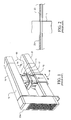
- Figure 3 is a top plan view, partially cut away, of a scanner incorporating the present invention.
- Figure 4 is a side elevational view of Figure 3.
- Figure 5 is a simplified view of one embodiment of an installed scanner of Figures 3 and 4.
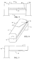
- Figure 6 is a perspective view of an alternative embodiment.
- Figure 7 is a side view of an alternative embodiment.
- Figure 8 is a cross-sectional view taken along the lines 8-8 of Figure 4.
- Figure 5 illustrates a typical embodiment of scanner 30 where there are a pair of spaced upper and lower beams 31 and 32 which are supported by left and right vertical supports 33a and 33b, the vertical supports being located at the left and right edges of a moving sheet of material 34 such as paper.
- the width of such paper might be from 6 to 10 feet. Because of the unique construction of the beams 31 and 32 and their associated gauging heads which scan across the paper 34 in the cross direction, the gap 36, between the beams 31 and 32, is relatively small.
- FIG. 8 where the cross-section of beam 31 is radon, its bottom-portion faces the moving sheet 34.
- insulated outer layer 40 is provided for condensation and thermal control insulated outer layer 40.
- a slot 38 in the bottom portion is, of course, in proximity to sheet 34 to allow an upper gauging head 39 to have its face 41 exposed through the slot to the sheet and interface with the sheet without physical interference for measuring a parameter of the sheet 34.
- a second beam 32 would normally be on the other side of sheet 34 so that, for example, for the measurement of basis weight, a promethium source 42 contained in the upper gauging head 39 transmits radiation through the sheet and the attenuation of that radiation determines basis weight.
- a pair of infrared wavelength beams are used for moisture, of course.
- Gauging head 39 is mounted for slidable cross-direction movement within the beam on a pair of rods 43a, 43b.
- a power track unit 46 in the form of cable with flexible links supplies the necessary electrical power, the signal line return path for measured parameters and any necessary cooling water or air to the gauging head 39.
- the tubular beam entirely contains and protects the gauging head 39 in its interior, and has as its only substantial opening, the slot 38.
- flexible drive belt means substantially contained within the tubular beam is connected to the gauging head 39 to both drive the gauging head in the cross direction and for sealing the length of the slot in the cross direction (by covering it), to protect the interior of the beam from ambient dust, dirt and air.
- Figure 4 illustrates this flexible plastic drive belt 51 which is temperature resistant, and which is connected to gauging head 39 at a pair of leading and lagging points 52 and 53. Thus its face 41 is thereby exposed.
- One fastening plate 52 is better illustrated in Figure 8.
- Belt 51 is driven by an appropriate motor 56 along with various pulleys 57, 58, 59, 61 and 62.
- Motor 56 as illustrated in Figure 3 also drives the power track unit 46.
- Belt 51 is a high precision timing belt available from BRECOFLEX CO. of EATONTOWN, N.J.
- the drive belt 51 is journaled in a pair of interior recesses 66 and 67 which are parallel to the slot 38.
- These recesses as illustrated in Figure 8 are preferably constructed of aluminum material or stainless steel which is located below slot 38 in the insulating material 40, but still fastened to the stainless steel tubular beam 37.
- the recesses could be a part of beam 37 or located in the interior of the beam in the same manner as shown on the exterior.
- the recesses provide an effective bearing for the belt 51, as well as an effective seal.
- air intake 71 is provided with an associated blower 72.
- the blower air inlet 71, 72 provides a positive pressure inside the beam greater than the ambient air pressure to prevent contamination inside the beam.
- the interior of beam forms an air plenum for cooling the interior gauging heads.
- FIG. 6 illustrates another embodiment where a single beam 77 is cantilevered from a vertical support 78 over the paper 74 or the moving sheet material 34.
Landscapes
- Physics & Mathematics (AREA)
- General Health & Medical Sciences (AREA)
- Pathology (AREA)
- Health & Medical Sciences (AREA)
- Life Sciences & Earth Sciences (AREA)
- Chemical & Material Sciences (AREA)
- Analytical Chemistry (AREA)
- Immunology (AREA)
- General Physics & Mathematics (AREA)
- Biochemistry (AREA)
- Textile Engineering (AREA)
- Engineering & Computer Science (AREA)
- Spectroscopy & Molecular Physics (AREA)
- Length Measuring Devices By Optical Means (AREA)
- Facsimile Scanning Arrangements (AREA)
- Optical Recording Or Reproduction (AREA)
Applications Claiming Priority (2)
| Application Number | Priority Date | Filing Date | Title |
|---|---|---|---|
| US487058 | 1983-04-21 | ||
| US09/487,058 US6253604B1 (en) | 2000-01-19 | 2000-01-19 | Scanner with interior gauging head and combined dust and drive belt |
Publications (2)
| Publication Number | Publication Date |
|---|---|
| EP1126274A2 true EP1126274A2 (fr) | 2001-08-22 |
| EP1126274A3 EP1126274A3 (fr) | 2002-09-11 |
Family
ID=23934230
Family Applications (1)
| Application Number | Title | Priority Date | Filing Date |
|---|---|---|---|
| EP01101087A Withdrawn EP1126274A3 (fr) | 2000-01-19 | 2001-01-18 | Balayeur avec tête de mesure intérieure et courroie de poussière et de transmission combinée |
Country Status (2)
| Country | Link |
|---|---|
| US (2) | US6253604B1 (fr) |
| EP (1) | EP1126274A3 (fr) |
Cited By (2)
| Publication number | Priority date | Publication date | Assignee | Title |
|---|---|---|---|---|
| EP1271130A1 (fr) * | 2001-06-20 | 2003-01-02 | Voith Paper Patent GmbH | Scanner |
| US6536270B1 (en) | 2000-01-19 | 2003-03-25 | Voith Paper Automation, Inc. | Scanner with interior gauging head and dust belt |
Families Citing this family (3)
| Publication number | Priority date | Publication date | Assignee | Title |
|---|---|---|---|---|
| CA2398867A1 (fr) * | 2002-08-20 | 2004-02-20 | Ivan Muchalov | Plaque tournante pour applications de chaines de production |
| US7301164B2 (en) * | 2004-01-30 | 2007-11-27 | Abb Inc. | Measuring apparatus |
| US8561468B2 (en) * | 2011-06-27 | 2013-10-22 | Honeywell Asca Inc. | Scanner diagnostics utilizing three axis accelerometers |
Citations (2)
| Publication number | Priority date | Publication date | Assignee | Title |
|---|---|---|---|---|
| US3621259A (en) * | 1969-01-17 | 1971-11-16 | Measurex Corp | Sheet-gauging apparatus |
| US5343296A (en) * | 1993-02-04 | 1994-08-30 | Abb Process Automation Inc. | Optical scanner with self contained standardization means |
Family Cites Families (15)
| Publication number | Priority date | Publication date | Assignee | Title |
|---|---|---|---|---|
| BE571375A (fr) * | 1958-04-11 | |||
| US3662174A (en) * | 1969-12-15 | 1972-05-09 | Industrial Nucleonics Corp | Nucleonic gauges having source window protector plates with compressed air wipe arrangements for use in oil spray environments |
| US3793524A (en) * | 1972-09-05 | 1974-02-19 | Measurex Corp | Apparatus for measuring a characteristic of sheet materials |
| US4766315A (en) * | 1986-07-14 | 1988-08-23 | Accuray Corporation | Apparatus and process for measuring physical parameters of sheet material |
| US4791353A (en) * | 1987-08-14 | 1988-12-13 | Impact Systems, Inc. | Scanning combination thickness and moisture gauge for moving sheet material |
| DE3827084C1 (fr) * | 1988-08-10 | 1989-11-16 | Sulzer-Escher Wyss Gmbh, 7980 Ravensburg, De | |
| US5164048A (en) * | 1990-08-29 | 1992-11-17 | Measurex Corporation | Cooling structure for stabilizing the temperature of beams in a sheet-making apparatus |
| US5165277A (en) * | 1990-08-29 | 1992-11-24 | Measurex Corporation | System and process for determining properties of a moving sheet of material |
| US5658432A (en) * | 1995-08-24 | 1997-08-19 | Measurex Devron Inc. | Apparatus and method of determining sheet shrinkage or expansion characteristics |
| SE504747C2 (sv) * | 1995-09-13 | 1997-04-14 | Valmet Karlstad Ab | Avsökningsanordning för avsökning av en fysikalisk egenskap hos en fiberbana |
| US5928475A (en) * | 1996-12-13 | 1999-07-27 | Honeywell-Measurex, Corporation | High resolution system and method for measurement of traveling web |
| US5773714A (en) * | 1997-02-19 | 1998-06-30 | Honeywell-Measurex Corporation | Scanner beam dynamic deflection measurement system and method |
| US6080278A (en) * | 1998-01-27 | 2000-06-27 | Honeywell-Measurex Corporation | Fast CD and MD control in a sheetmaking machine |
| US6168687B1 (en) * | 1998-04-24 | 2001-01-02 | Honeywell-Measurex Corporation | System and method for sheet measurement and control in papermaking machine |
| US6253604B1 (en) | 2000-01-19 | 2001-07-03 | Impact Systems, Inc. | Scanner with interior gauging head and combined dust and drive belt |
-
2000
- 2000-01-19 US US09/487,058 patent/US6253604B1/en not_active Expired - Fee Related
-
2001
- 2001-01-18 EP EP01101087A patent/EP1126274A3/fr not_active Withdrawn
- 2001-06-20 US US09/885,941 patent/US6536270B1/en not_active Expired - Fee Related
Patent Citations (2)
| Publication number | Priority date | Publication date | Assignee | Title |
|---|---|---|---|---|
| US3621259A (en) * | 1969-01-17 | 1971-11-16 | Measurex Corp | Sheet-gauging apparatus |
| US5343296A (en) * | 1993-02-04 | 1994-08-30 | Abb Process Automation Inc. | Optical scanner with self contained standardization means |
Cited By (2)
| Publication number | Priority date | Publication date | Assignee | Title |
|---|---|---|---|---|
| US6536270B1 (en) | 2000-01-19 | 2003-03-25 | Voith Paper Automation, Inc. | Scanner with interior gauging head and dust belt |
| EP1271130A1 (fr) * | 2001-06-20 | 2003-01-02 | Voith Paper Patent GmbH | Scanner |
Also Published As
| Publication number | Publication date |
|---|---|
| US6253604B1 (en) | 2001-07-03 |
| EP1126274A3 (fr) | 2002-09-11 |
| US20030056582A1 (en) | 2003-03-27 |
| US6536270B1 (en) | 2003-03-25 |
Similar Documents
| Publication | Publication Date | Title |
|---|---|---|
| FI94176C (fi) | Menetelmä ja laite liikkuvan radan reunan seurannassa | |
| US6749723B2 (en) | Measuring arrangements in a shortened dry end of a tissue machine | |
| CA2721583C (fr) | Stabilisation de feuille a l'aide de doubles dispositifs de serrage pneumatiques a direction croisee opposee | |
| US6253604B1 (en) | Scanner with interior gauging head and combined dust and drive belt | |
| EP1039262A3 (fr) | Procédé et appareil pour la mesure de l' épaisseur ed du gonflement des feuilles | |
| EP2201333B1 (fr) | Reduction du nombre de cables dans un porte-cables d'un scanner a papier | |
| WO2013044358A1 (fr) | Procédé de mesure de l'épaisseur d'une bande en mouvement | |
| US5343296A (en) | Optical scanner with self contained standardization means | |
| US6133578A (en) | Nuclear gauge for measuring a characteristic of moving sheet material and alignment compensation | |
| EP0347331A3 (fr) | Dispositif de mesure de la tension d'une bande | |
| US5587051A (en) | Simplified laser apparatus and method for measuring stock thickness on papermaking machines | |
| EP1271130A1 (fr) | Scanner | |
| CA2229499A1 (fr) | Dispositif de balayage servant a mesurer les proprietes physiques d'une bande fibreuse | |
| US7678233B2 (en) | Machine direction sensor system with cross direction averaging | |
| CN103608685B (zh) | 使用三轴加速度计的扫描器诊断 | |
| US7390379B2 (en) | Method and apparatus for determining the lateral position of a web or fabric edge in a former | |
| FI841959A0 (fi) | Foerfarande och anordning foer detektering och avvaerjning av massautloppsoeppningen i en pappersmaskins tryckbox. | |
| US7396437B2 (en) | Method and system for controlling the web formation | |
| US20250305965A1 (en) | Compact-cross direction c-frame scanner | |
| CN220040249U (zh) | 一种烟草物料水分检测设备 | |
| FI20216133A1 (en) | A device for measuring the temperature of the moving metal belt of a fiber handling device | |
| CA1265940A (fr) | Methode et m oyen pour mesurer la repartition transversale de la tension dans un materiau en bande | |
| JP3119391B2 (ja) | オンライン検出装置 | |
| JPS57158511A (en) | Coating thickness measuring method of synthetic resin coating steel pipe | |
| JPH08213673A (ja) | 光学装置の支持構造 |
Legal Events
| Date | Code | Title | Description |
|---|---|---|---|
| PUAI | Public reference made under article 153(3) epc to a published international application that has entered the european phase |
Free format text: ORIGINAL CODE: 0009012 |
|
| AK | Designated contracting states |
Kind code of ref document: A2 Designated state(s): AT BE CH CY DE DK ES FI FR GB GR IE IT LI LU MC NL PT SE TR |
|
| AX | Request for extension of the european patent |
Free format text: AL;LT;LV;MK;RO;SI |
|
| PUAL | Search report despatched |
Free format text: ORIGINAL CODE: 0009013 |
|
| AK | Designated contracting states |
Kind code of ref document: A3 Designated state(s): AT BE CH CY DE DK ES FI FR GB GR IE IT LI LU MC NL PT SE TR |
|
| AX | Request for extension of the european patent |
Free format text: AL;LT;LV;MK;RO;SI |
|
| 17P | Request for examination filed |
Effective date: 20021010 |
|
| AKX | Designation fees paid |
Designated state(s): AT DE FI SE |
|
| 17Q | First examination report despatched |
Effective date: 20040408 |
|
| STAA | Information on the status of an ep patent application or granted ep patent |
Free format text: STATUS: THE APPLICATION IS DEEMED TO BE WITHDRAWN |
|
| 18D | Application deemed to be withdrawn |
Effective date: 20041019 |