EP1126293A2 - Optischer Multiplex-/Demultiplex-Schaltkreis - Google Patents
Optischer Multiplex-/Demultiplex-Schaltkreis Download PDFInfo
- Publication number
- EP1126293A2 EP1126293A2 EP00310572A EP00310572A EP1126293A2 EP 1126293 A2 EP1126293 A2 EP 1126293A2 EP 00310572 A EP00310572 A EP 00310572A EP 00310572 A EP00310572 A EP 00310572A EP 1126293 A2 EP1126293 A2 EP 1126293A2
- Authority
- EP
- European Patent Office
- Prior art keywords
- interleaver
- filters
- circuit
- interleavers
- etalon
- Prior art date
- Legal status (The legal status is an assumption and is not a legal conclusion. Google has not performed a legal analysis and makes no representation as to the accuracy of the status listed.)
- Withdrawn
Links
Images


Classifications
-
- G—PHYSICS
- G02—OPTICS
- G02B—OPTICAL ELEMENTS, SYSTEMS OR APPARATUS
- G02B6/00—Light guides; Structural details of arrangements comprising light guides and other optical elements, e.g. couplings
- G02B6/24—Coupling light guides
- G02B6/26—Optical coupling means
- G02B6/28—Optical coupling means having data bus means, i.e. plural waveguides interconnected and providing an inherently bidirectional system by mixing and splitting signals
- G02B6/293—Optical coupling means having data bus means, i.e. plural waveguides interconnected and providing an inherently bidirectional system by mixing and splitting signals with wavelength selective means
- G02B6/29331—Optical coupling means having data bus means, i.e. plural waveguides interconnected and providing an inherently bidirectional system by mixing and splitting signals with wavelength selective means operating by evanescent wave coupling
- G02B6/29335—Evanescent coupling to a resonator cavity, i.e. between a waveguide mode and a resonant mode of the cavity
- G02B6/29338—Loop resonators
-
- G—PHYSICS
- G02—OPTICS
- G02B—OPTICAL ELEMENTS, SYSTEMS OR APPARATUS
- G02B6/00—Light guides; Structural details of arrangements comprising light guides and other optical elements, e.g. couplings
- G02B6/24—Coupling light guides
- G02B6/26—Optical coupling means
- G02B6/28—Optical coupling means having data bus means, i.e. plural waveguides interconnected and providing an inherently bidirectional system by mixing and splitting signals
- G02B6/293—Optical coupling means having data bus means, i.e. plural waveguides interconnected and providing an inherently bidirectional system by mixing and splitting signals with wavelength selective means
- G02B6/29346—Optical coupling means having data bus means, i.e. plural waveguides interconnected and providing an inherently bidirectional system by mixing and splitting signals with wavelength selective means operating by wave or beam interference
- G02B6/29358—Multiple beam interferometer external to a light guide, e.g. Fabry-Pérot, etalon, VIPA plate, OTDL plate, continuous interferometer, parallel plate resonator
-
- G—PHYSICS
- G02—OPTICS
- G02B—OPTICAL ELEMENTS, SYSTEMS OR APPARATUS
- G02B6/00—Light guides; Structural details of arrangements comprising light guides and other optical elements, e.g. couplings
- G02B6/24—Coupling light guides
- G02B6/26—Optical coupling means
- G02B6/28—Optical coupling means having data bus means, i.e. plural waveguides interconnected and providing an inherently bidirectional system by mixing and splitting signals
- G02B6/293—Optical coupling means having data bus means, i.e. plural waveguides interconnected and providing an inherently bidirectional system by mixing and splitting signals with wavelength selective means
- G02B6/29379—Optical coupling means having data bus means, i.e. plural waveguides interconnected and providing an inherently bidirectional system by mixing and splitting signals with wavelength selective means characterised by the function or use of the complete device
- G02B6/2938—Optical coupling means having data bus means, i.e. plural waveguides interconnected and providing an inherently bidirectional system by mixing and splitting signals with wavelength selective means characterised by the function or use of the complete device for multiplexing or demultiplexing, i.e. combining or separating wavelengths, e.g. 1xN, NxM
- G02B6/29386—Interleaving or deinterleaving, i.e. separating or mixing subsets of optical signals, e.g. combining even and odd channels into a single optical signal
-
- G—PHYSICS
- G02—OPTICS
- G02B—OPTICAL ELEMENTS, SYSTEMS OR APPARATUS
- G02B6/00—Light guides; Structural details of arrangements comprising light guides and other optical elements, e.g. couplings
- G02B6/24—Coupling light guides
- G02B6/26—Optical coupling means
- G02B6/28—Optical coupling means having data bus means, i.e. plural waveguides interconnected and providing an inherently bidirectional system by mixing and splitting signals
- G02B6/293—Optical coupling means having data bus means, i.e. plural waveguides interconnected and providing an inherently bidirectional system by mixing and splitting signals with wavelength selective means
- G02B6/29331—Optical coupling means having data bus means, i.e. plural waveguides interconnected and providing an inherently bidirectional system by mixing and splitting signals with wavelength selective means operating by evanescent wave coupling
- G02B6/29332—Wavelength selective couplers, i.e. based on evanescent coupling between light guides, e.g. fused fibre couplers with transverse coupling between fibres having different propagation constant wavelength dependency
Definitions
- This invention relates to a multiplexor/demultiplexor for multiplexing and demultiplexing optical signals. More particularly, the invention relates to a method and system for filtering or separating closely spaced signal channels that would otherwise not be suitably filtered by conventional optical filters.
- optical signals as a means of carrying channeled information at high speeds through an optical path such as an optical waveguide i.e. optical fibres, is preferable over other schemes such as those using microwave links, coaxial cables, and twisted copper wires, since in the former, propagation loss is lower.
- Optical systems are immune to Electro-Magnetic Interference (EMI), and have higher channel capacities. High-speed optical systems have signaling rates of several mega-bits per second to several tens of giga-bits per second.
- EMI Electro-Magnetic Interference
- Optical communication systems are nearly ubiquitous in communication networks.
- the expression herein "Optical communication system” relates to any system that uses optical signals at any wavelength to convey information between two points through any optical path.
- Optical communication systems are described for example, in Gower, Ed. Optical communication Systems, (Prentice Hall, NY) 1993, and by P.E. Green, Jr. in “Fiber optic networks” (Prentice Hall New Jersey) 1993, which are incorporated herein by reference.
- High speed data signals are plural signals that are formed by the aggregation (or multiplexing) of several data streams to share a transmission medium for transmitting data to a distant location.
- Wavelength Division Multiplexing is commonly used in optical communications systems as means to more efficiently use available resources.
- WDM Wavelength Division Multiplexing
- each high-speed data channel transmits its information at a pre-allocated wavelength on a single optical waveguide.
- channels of different wavelengths are generally separated by narrow band filters and then detected or used for further processing.
- the number of channels that can be carried by a single optical waveguide in a WDM system is limited by crosstalk, narrow operating bandwidth of optical amplifiers and/or optical fiber nonlinearities.
- such systems require an accurate band selection, stable tunable lasers or filters, and spectral purity that increase the cost of WDM systems and add to their complexity.
- the GT device provides some of the functionality provided by the instant invention.
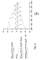
- the GT device as exemplified in Fig. 1 serves as a narrow band wavelength demultiplexor; this device relies on interfering a reflected E-field with an E-field reflected by a plane mirror 16.
- the etalon 10 used has a 99.9% reflective back reflector 12r and a front reflector 12f having a reflectivity of about 10%; hence an output signal from only the front reflector 12f is utilized.
- a beam splitting prism (BSP) 18 is disposed to receive an incident beam and to direct the incident beam to the etalon 10.
- the BSP 18 further receives light returning from the etalon and provides a portion of that light to the plane mirror 16 and a remaining portion to an output port.
- Fig. 1a shows a graph with a linear plot of the phase difference between the two reflected E-fields from the GT and a mirror with an optical path difference. Further, the graph shows a linear plot of phase variation of reflected light from the GT. A reflection profile is also shown in a logarithmic plot, and a straight sloped dotted line is a linear plot of a GT with a finite optical path difference.
- FSR free-spectral range
- an interleaver/de-interleaver optical circuit for interleaving or deinterleaving an input optical signal having a plurality of channels of predetermined inter-channel frequency spacing, comprising a plurality of sub- interleaver/de-interleavers, each sub-interleaver/de-interleaver being optically coupled to at least one other sub- interleaver/de-interleaver for providing an output signal thereto, or for receiving an output signal therefrom, each of the sub-interleaver/de-interleavers having a substantially same free-spectral range and a shifted spectral response relative to the other sub-interleavers/de-interleavers, each of the sub- interleaver/de-interleavers for interleaving or de-interleaving a substantially different group of periodic channels having different centre wavelengths.
- a method of de-interleaving a multi-channel optical signal comprising the steps of: passing an input signal having a plurality of channels of a predetermined spacing through a plurality of sequentially coupled periodic de-interleaving filters having each a substantially same period, and wherein peak centre passbands of the filters are offset from one another, the filters being arranged such that one of the filters is optically coupled to receive or provide a signal to another of the filters, and wherein the period of the filters is greater than two adjacent inter-channel frequency spacings of said input signal.
- An aspect of this invention provides a system for de-interleaving a multi-channel optical signal, comprising: a plurality filters having a periodic output response each having a period T, wherein peak centre passbands of the filters are offset from one another by a predetermined amount, the filters being arranged such that each of the filters is optically coupled to receive or provide a signal to another of the filters, the filters having a substantially symmetric output response.
- interleavers with n ⁇ T (n>2) output channel spacing can be used to interleave channels separated by a spacing of ⁇ T.
- This device is less bulky than using a serial approach of feeding the output of a first de-interleaving stage to two subsequent stages and feeding the outputs of the second two stages to four further de-interleaving stages and so on.
- each next stage has twice the free spectral range (FSR) than the previous stage (i.e. when starting with input signal channel spacing of 50 GHz, the first interleaver spacing would be 100 GHz, the next spacing would be 200 GHz, then 400 GHz etc.).
- FSR free spectral range
- Another advantage is that plural similar devices can be used for all interleaving stages.
- Another advantage is that the de-interleaved channels' pass band can be very wide.
- system in accordance with an embodiment of the invention can be used to de-interleave irregular spaced channels which may be employed to suppress four wave mixing in a WDM transmission system when the adjacent channel spacing is less than 100 GHz.
- This invention allows a same etalon based device to be used repeatedly by interconnecting these same etalons and angle tuning them to provide different output responses from each etalon based interleaver. This has significant cost and reliability advantages. Furthermore stocking different etalons with significantly different free-spectral ranges is not required.
- the spectral characteristics of an etalon filter are determined by the reflectivity and gap spacing of the mirrors or reflective surfaces.
- the Fabry-Perôt principle allows a wideband optical beam to be filtered whereby only periodic spectral passbands are substantially transmitted out of the filter. Conversely, if the reflectivity of the mirrors or reflective surfaces are selected appropriately, periodic spectral passbands shifted by d nanometers are substantially reflected backwards from the input mirror surface.
- adjustable Fabry-Perôt devices such as one disclosed in United States Patent number 5,283,845 in the name of Ip, assigned to JDS Fitel Inc, tuning of the center wavelength of the spectral passband is achieved typically by varying the effective cavity length (spacing).
- an optical circuit for demultiplexing a channeled optical signal, that is, a signal comprising multiplexed closely spaced channels, into a plurality of less-dense channeled signals each comprising a plurality of multiplexed less closely spaced channels.
- a channeled optical signal that is, a signal comprising multiplexed closely spaced channels
- the circuit operates in a first direction wherein the circuit performs a multiplexing function on a plurality of channels launched into an end of the circuit, it is an interleaver circuit, and in an opposite direction wherein the circuit performs a demultiplexing function on a composite signal launched therein at an opposite end to provide a plurality of demultiplexed channels it serves as a de-interleaver circuit.
- interleaver circuit shall be used hereafter to denote this interleaver/de-interleaver circuit.
- One such interleaver circuit is disclosed as a comb splitting. filter in U.S. Patent No. 5,680,490 in the name of Cohen.
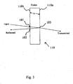
- an optical interleaver circuit including a 3-port optical cavity in the form of a Fabry-Perôt etalon filter 110 (shown in more detail in Fig. 3) having a first partially reflective end face 110a and a second partially reflective end face 110b.
- the Fabry-Perôt etalon has an input port 101 at end face 110b, a second port 102 at the Fabry-Perôt etalon filter reflection end face 110, and a third port 103 coupled to a transmission end face 110a serving as an output port.
- the Fabry-Perôt etalon filter 110 has two partially reflective mirrors, or surfaces, facing each other and separated by a certain fixed gap which forms a cavity.
- a phase shifter for controllably delaying an optical signal passing therethrough is optically coupled with the third port 103 at an end of the Fabry-Perôt etalon 110.
- a 50/50 splitter 119 is disposed between and optically coupled with an output end of the phase shifter 117 and the second port 102 of the Fabry-Perôt etalon 110.
- waveguides for example, optical fibres for directing signals from the etalon to the phase shifter 117 and splitter 119
- less preferable free space implementations using mirrors or reflectors are within the capability of one skilled in the art.
- coupling lenses such as GRIN lenses are preferred for coupling light from and or to optical fibres from particular components.
- phase difference between the reflected and transmitted E-field phase from an etalon remains constant under certain circumstances.
- the phase difference between a resulting signal exiting the end face 103 and a resulting signal exiting the end face 102 is either 0 or ⁇ radians, and changes on every spectral transmission resonance. This is illustrated in Fig. 2a, where phase is plotted versus wavelength. The locking of the phase difference between transmitted and reflected E-fields occurs due to multiple interference effects within the etalon.
- An embodiment of this invention utilizes this feature by interfering the two resulting signals, by way of example, so that a flat spectral passband filter can be realized.
- a flat spectral passband filter can be realized.
- various desired output responses can be realized.
- additional control can be added to either attenuate or amplify one of or both of the two signals.
- phase shifter 117 ensures a means of adjusting for unwanted or desired phase differences due to path length differences.
- the outputs from the interferometer now have a ⁇ phase shift, which indicates that useful or a desired interferometric action between the two signals can exist.
- channel selection can be realized.
- the circuit can operate as a de-interleaver filter, providing the separation of odd channels at one output of the splitter and even channels at a second output of the splitter.
- the interleaving function disappears and the circuit operates to provide a linearized output.
- a linearized output signal is useful in such applications as wavelength locking, where a linear ramped signal is desired.
- the two output signals are subtracted from one another, the effect is further enhanced since no loss of the signal will be induced.
- FIGs, 4a through 4c an optical device is shown in accordance with the invention embodying a free-space device wherein unguided collimated light propagates within the device.
- the interleaver/de-interleaver shown has two glass interferometric end plates 42 having a spacer disposed therebetween.
- the spacer region between the two interferometric end plates 42 has a 50/50 coating (shown) except for where a dotted line is shown.
- This dotted line represents the region between the plates 42 where the etalon is formed (not shown in detail) of two at least partially reflecting surfaces having an air gap there between having a predetermined dimension of >5 ⁇ defining the free spectral range of the etalon.
- Graded index (GRIN) lenses 40a, through 40c in Figs. 4a and 4b serve to provide collimated light through and between the end plates 42, and serve as focusing lenses at output ports.
- Mirrors 41a and 41b, are disposed at ends of the plates 42 to direct the beam toward a particular port.
- light launched into an input port at lens 40a is directed at the etalon between the plates. About 50% of the light is transmitted through the front end of the etalon and follows a path wherein the light is incident upon the mirror 41a and it is subsequently directed to the lens 41b; the remaining light is transmitted through the back side of the etalon and impinges upon the mirror 41b where it is subsequently directed to the port at lens 40c.
- channels having centre wavelengths ⁇ 1, ⁇ 2, ⁇ 3, ⁇ 4, Vietnamese ⁇ n are launched into the port at lens 40a, the channels are de-interleaved at the ports at lenses 40b and 40c into channel groups ⁇ 1, ⁇ 3, ⁇ 5 and ⁇ 2, ⁇ 4, ⁇ 6...
- Fig. 4b illustrates how the same circuit of Fig. 4a can be used backwards to interleave de-interleaved channels.
- Fig. 4c illustrates that an extra input port at GRIN lens 40d can be added and the circuit can be used to switch input channels to either output port by appropriately adjusting and controlling the phase.
- an optical device embodying a free-space device wherein unguided collimated light propagates within the device.
- the interleaver/deinterleaver shown has two glass interferometric end plates 42 having a spacer disposed therebetween. The end plates and the spacer are joined by optical contacting. These contacting surfaces are polished simultaneously and in the same orientation in order to keep their surfaces parallel within 10 arc seconds when assembled.
- the axis of the through hole of the interferometric combiner and the axis of the coating B on each of the interferometric endplates are concentric within 0.1 mm.
- the interferometric combiner is conveniently embodied by a 50/50 coating. The etalon is absent this coating.
- Temperature sensors 52 are shown at ends of the plates 52 to determine the relative temperature difference between the two interferometric end plates 42. Heaters 42a and 42b which are conveniently wrapped around the end plates 42 are used with the temperature sensors 52 to control the phase relationship between the transmitted and reflected optical signals passing through opposite ends of the etalon.
- an odd-integer number multi-cavity etalon is used in a same manner as was the single etalon described heretofore.
- light is captured and combined from outermost opposite ports of the multi-cavity etalon structure.
- multi-cavities i.e. three etalons
- the profile shown in Fig. 6a is acquired wherein there is an increase in the phase at certain portions 62 of the graph which result in a steeper sharper output response.
- more etalon surfaces i.e. at least four reflective surfaces in the instance of a three cavity etalon, more control is afforded by being able to change the reflectivites of each surface.
- FIG. 6b illustrates two plots, one in dotted outline, which represents a portion of an output spectrum for a single cavity etalon and a solid line which represents the same portion of the output spectrum for a three cavity etalon device, in accordance with the invention.
- Fig. 6c illustrates the circuit in accordance with this invention having a multi-cavity etalon coupled to a combiner.
- the phase shifter has ensured an effective phase difference of ⁇ /2, so that the phase shift incurred through the 50/50 splitter has been compensated. This, then, has allowed complete constructive and destructive interference to occur in the interferometer outputs.
- a different phase difference is used, then with a certain combination of reflectivities for the two facets of the etalon, a linearized intensity variation with wavelength as shown in the graph of Fig. 7 can be achieved.
- the reflection coefficients are 0.01 and 0.6 and the phase difference is 0.
- Fig. 8 illustrates an alternative embodiment whereby a flat filter pass band is provided by using the correct phase difference and reflectivities.
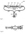
- FIG. 9 an alternative embodiment is provided which is functionally similar to the embodiment shown in Fig. 2.
- An interleaver circuit 900 is shown that can be conveniently made using planar waveguide technology.
- the waveguides can, for example, be disposed in glass.
- the waveguide regions can be doped, ion implanted, or grafted.
- the core light guide regions can be a light transmissive polymer.
- a first MMI 50/50 coupler 910 having an input port 1 and an output port 2 at a first end is optically coupled to a second, same MMI 50/50 coupler 920 by way of waveguides 912 and 914 disposed therebetween.
- Two thin partially reflecting plates E and E' are disposed in grooves cut into the waveguides 912 and 914.
- Plate E, waveguide 912 disposed therebetween, and plate E' form a first Fabry-Perôt etalon.
- plate E, waveguide 914 disposed therebetween, and plate E' form a second Fabry-Perôt etalon.
- An output port 2 of the first MMI coupler 910 and an output port 2 of the second MMI coupler 920 are coupled to input ports 1 and 2 of a third MMI 50/50 coupler 930 having output ports 3 and 4 for carrying signals a out1 and a out2 respectively.
- Fig. 10 is used as a means of describing the functionality of a four-port 3 dB coupler, similar to the ones shown in Fig. 9.
- An input signal a 1 provided to port 1 of the coupler 940 is divided equally between ports 2 and 3. After the signals are reflected backwards by the mirror, shown, they are combined into port 4 of the coupler not port 1. In this manner, the reflected signal is separated from the input signal without the requirement of an optical circulator.
- the MMI couplers shown in Fig. 9 could be replaced with 3 dB couplers.
- Fig. 9 The operation of the circuit of Fig. 9 is similar to the operation of the de-interleaver/interleaver shown in Fig. 2.
- an input signal a in is launched into port 1 and is divided equally into two de-interleaved signals on waveguides 912 and 914 at ports 3 and 4 respectively of the coupler 910.
- the transmission signal a t and reflection signal a r transmitted through and reflected from the etalon between the couplers 910 and 920 are input into port 1 and 2 of the MMI coupler 930 and are provided as two de-interleaved output signals.
- each de-interleaved output stream can be provided to yet another similar de-interleaving circuit for further de-interleaving the channelized signals.
- channels 1, 3, 5, 7, ... are output on a out1 and channels 2, 4, 6, 8, ... are output on a out1 .
- channels 1, 3, 5, 7, 9, can be fed to a similar circuit to circuit 900 wherein the etalon has a greater FSR so that two other data streams 1, 5, 9 and, 3, 7, 11 can further be demultiplexed.
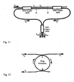
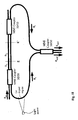
- Fig. 11 Another similar embodiment to that of Fig. 9 is shown in Fig. 11 wherein an etalon 111 is formed between the two MMI couplers 910 and 920 by way of providing a region in each waveguide 912 and 914 wherein the refractive index is different from the refractive index of the waveguides coupled to and adjacent to this region.
- the etalon region can be a polymer having a suitable refractive index.
- the length of the etalon, and refractive index difference between the etalon region and adjacent regions must be sufficient such as to provide a desired reflectivity at the interface between different index regions.
- Fig. 12 depicts a functionally similar embodiment to a Fabry-Perôt etalon.
- the circuit shown in Fig. 12 utilizes a ring resonator.
- An equivalent transfer function of a Fabry-Perôt resonator can be obtained by combining a waveguide ring resonator and two directional couplers as is shown. This is a 3-port device with one input port and two output ports. The signals a r and a t at the output ports of the device are equivalent to the reflected and transmitted signals of a Fabry-Perôt resonator.
- the coupling coefficients of the directional couplers control the finesse of the cavity.
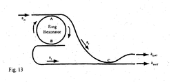
- FIG. 13 An embodiment in accordance with this invention is shown in Fig. 13.
- the two outputs of the ring resonator are routed to a 3 dB coupler to obtain two interleaved signals, a out1 and a out2 ..
- An interleaving function can be realized if the optical length AC is equal to the optical length BC, wherein the optical length is the physical length x the refractive index. Of course the physical length is somewhat restricted by the amount of bending that can be tolerated.
- the coupler is a 50/50 coupler.
- the coupler at C can be a directional coupler or an MMI coupler. It is preferred that the couplers at A and B are 17.1% / 82:9% couplers, such that 82.9% of the light is coupled into the ring, and 17.1% of the light passes through the waveguides adjacent the ring.
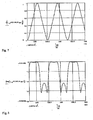
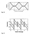
- Figs. 14 and 15 show the spectral amplitude and the phase responses of the two outputs, a r and a t , of the ring resonator.
- Figure 16 shows the phase difference between the two outputs, a r and a t , of the ring resonator. The phase difference alternates between - ⁇ /2 and + ⁇ /2 over consecutive wavelength channels equivalent to the FSR of the ring resonator.
- Figure 17 shows the spectral transmissions of the two de-interleaved signals, a out1 and a out2 , at the outputs of the waveguide coupler interferometer.
- the monolithic waveguide devices described in accordance with this invention can be fabricated in such a way as to make them relatively temperature stable by permanently tuning the device.
- one of the arms, a r or a t can be doped, for example with germanium and subsequently exposed to UV light, in order to vary the refractive index of a particular section of the doped arm.
- exposing one arm to light of a suitable intensity and duration can in some instances yield a required refractive index change to permanently tune the device. This is a convenient method shown in Fig. 18 of permanently adjusting the phase relationship between the two arms a r and a t thereby yielding very temperature tolerant devices.
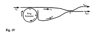
- FIG. 19 An alternative embodiment is shown in Fig. 19 wherein a de-interleaver/interleaver is shown.
- the locations A and B are shown to be 90 degrees apart.
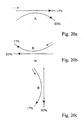
- Figs. 20a, 20b, and 20c illustrate approximate power coupling ratios in couplers A, B, and C.
- interleaver circuits which can de-interleave a stream of input channels into two de-interleaved streams, or conversely, which can interleave two input streams of channels into a single multiplexed interleaved stream.
- Group 1 and group 2 can then individually be fed into de-interleavers having a larger (200 Ghz) spacing, to yield: group 1a consisting of channels 1 and 5, and group 1b consisting of channels 3 and 7; simultaneously in another de-interleaver, group 2 can be divided into group 2a: consisting of channels 2 and 6 and group 2b consisting of channels 4 and 8. It is evident that interleaver/de-interleaver circuits to de-interleave group 1(2) must have a substantially different FSR than to de-interleave group 1a (2a).
- the first interleaver must have an FSR of 100 Ghz and the second interleaver must have an FSR of 200 GHz, and if a third (and fourth) stage is required, the interleaver would be require to have an FSR of approximately 400 and 800 Ghz respectively.
- FSR FSR
- This invention provides a solution where a single periodic filter can be used to obviate the use of filters having 100 GHz, 200 GHz and 400 GHz channel spacing.
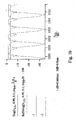
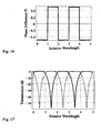
- Fig. 21 an amplitude-wavelength (A/ ⁇ ) graph of the transmission/ reflection spectrum from an etalon in accordance with this invention is shown.
- the transmission spectrum is indicated with T, and the reflection spectrum with R.
- the etalon is designed such that the reflection band (width) L 2 is triple the transmission pass band L 1 ; the centre wavelengths can be tuned with a very small change in FSR resulting.
- a de-interleaving/interleaving system wherein four interleavers/de-interleavers 201a, 201b, 201c and 201d are provided having etalons of substantially the same FSR.
- the four interleavers are identical and any required tuning to vary the relative responses of the etalons is provided by active tuning.
- This form of active tuning can be in the form of temperature tuning as shown in Fig. 23 with the provision of a heater 208 on the etalon 210, or by varying the angle ⁇ of the input signal a small amount to change the optical path length traversed by the incoming signal.
- active tuning can be in the form of temperature tuning as shown in Fig. 23 with the provision of a heater 208 on the etalon 210, or by varying the angle ⁇ of the input signal a small amount to change the optical path length traversed by the incoming signal.
- active tuning can be in the form of temperature tuning as shown in Fig. 23 with the provision of a
- all of the etalons can be tunable having piezoelectric transducers (not illustrated) for slightly varying the gap within the cavity.
- the output response of etalon 201c is shifted from the output response of interleaver 201a to provide a shift of 50 GHz; the output response of interleaver 201b is shifted form the output response of interleaver 201a by 100 Ghz; and, the output response of interleaver 201d is shifted by 150 Ghz from the output response of interleaver 201a.
- de-interleaving of eight channels into four streams of two channels can be achieved by using four interleavers with etalons having substantially the same FSR.
- the two output streams from the de-interleaver, the reflected stream and the transmitted stream, are divided such that the transmitted stream 204 (ch1, ch5...) is passed for further processing if necessary, while the reflected stream 206 is passed to the second interleaver 201b for further de-interleaving.
- the second de-interleaver 201b with its spectral response being shifted by 100 Ghz relative to the first de-interleaver 210a, produces a transmitted stream with channels ch3 and ch7.
- the third interleaver produces a transmitted stream with channels ch2 and ch6 and a reflected stream with channels ch4 and ch8. It will be noted that if the 200 Ghz spacing thus produced in the output streams is sufficient, the fourth interleaver is not necessary. It can however be used to "clean up" a stream produced by the other filters, if desired.
- the factor of four (200 GHz compared to 50 GHz) applied in the example is not mandatory. The principle applies if the factor is three, five or greater. It appears however that the deinterleaving of every fourth channel provides a conveniently and sufficiently large channel spacing in the output signal for further processing.
- Fig. 23 shows how the temperature of the etalons or the angles of their input signals can be varied to provide a small shift in the output response of the etalons.
- Fig. 23 illustrates a Fabry- Perôt etalon based interleaver having an etalon 210 with a heating element 208 for tuning purposes.
- the input signal 209 is shown passing through the etalon 210 at an angle ⁇ .
- the reflected beam 211 and the transmitted beam 213 are combined at a mixing region 215 to produce two "arms" or groups 217, 219 of de-interleaved signals.
- the interleaver circuit is a so-called symmetrical circuit. If the channel spacings are different (but not random), the circuit can easily be adapted. For instance, if the channel spacing between channels 1 and 2, 2 and 3, 3 and 4, 5 and 6, 6 and 7... is 50 GHz, and the channel spacing between channels 4 and 5, 8 and 9... is 60 GHz, then the interleavers according to the invention would be designed for 210 GHz (3x50 + 60). It can be seen that the circuit of the invention can be adapted to various signals with irregularly spaced channels.
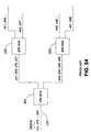
- FIG. 24 shows schematically a prior art circuit for processing an input signal 225 with eight channels ch1...ch8 of 50 GHz spacing therebetween.
- Three interleavers 221, 222 and 223 are coupled in an arrangement in which the first interleaver 221 is a 100 GHz periodic interleaver but the two next interleavers 222,223 are 200 GHz interleavers/de-interleavers. It is obvious that if another interleaving step is desired, the next four interleavers would be necessary, each being a 400 GHz interleaver/de-interleaver.
- the drawback of a plurality of different de-interleavers being necessary in the prior art circuit is eliminated by the present invention wherein all the interleavers/de-interleavers are substantially identical.
- interleavers based on other types of resonating cavities than etalons.
- the interleaving function may be provided for example by a ring resonator.
- a symmetric interleaver/de-interleaver has an input port and two output ports.
- the pass band bandwidth is equal to the stop band bandwidth.
- interleavers 300a, 300b, and 300c are coupled together such that interleaver 300b has its output ports coupled to input ports of interleavers 300a and 300c.
- Each of the interleavers are formed of substantially identical etalons that inherently have a substantially same FSR but are angle tuned to provide a periodic output response having a centre wavelength that is shifted by 50 GHz. It should be understood, that the shift is conveniently selected to be 50 GHz however could be a different arbitrary value.
- the output response of the interleaver 300b is shown in dotted outline for each of its two output ports. This corresponds with the output response for the interleaver shown in Fig. 25.
- an output port of the interleaver 300b is fed to the interleaver 300c. Since the output response of interleaver 300c is shifted by 50 GHz, the input signal present at port 3 is filtered in such a manner as to pass only half of it to be output.
- interleaver 300c effectively slices the input signal into two sub-signals, a first on port 3 comprising channels 3, 7, and 11, and a second on port 4 comprising 4, 8, and 12.
- channels having a bandwidth of 50 GHz are shown, however this is arbitrary.
- the channel bandwidth could be adjusted to be smaller or larger.
- One important advantage of this invention is that same etalons can be used for interleavers 300a, 300b and 300c, wherein during fabrication, angle tuning is employed to provide a required channel offset.
- the very small variation in FSR due to providing different optical path lengths through the etalons is negligible; notwithstanding, this variation provides a required channel offset required.
- Using substantially same etalons interconnected as shown provides increased reliability and greatly lessens the cost of manufacturing the device.
- Another advantage of this embodiment is that wide channel spacing can be provided.
- a stream of closely spaced 50 GHz input channels are demultiplexed into four 200 GHz spaced channel streams wherein channels 1, 5, and 9 are output on port 1; channels 2, 6, and 10 are output on port 2; channels 3, 7, and 11 are output on port 3, and channels 4, 8, and 12 are output on port 4.
- an interleaver having a 50:50 wavelength independent power splitter 402 having output ports connected to input ports of de-interleavers 400a and 400b.
- the output ports of 400a and 400b are fed to substantially same interleavers 400c, 400d, 400e, and 400g, having shifted output responses from one another.
- the power splitter provides two same streams having equal power output and consisting of all channels provided to its input port.
- the bandwidth can be adjusted and the output can be adjusted to being symmetrical or asymmetrical.
- the output channel width can be adjusted to any width less than the narrowest single coupler's bandwidth. This design advantageously offers flexibility with regard to the output signal bandwidth, and the channel shape between different output ports need not be the same.
- By having an asymmetrical scheme a different port can be used for a signal having a different modulation rate.
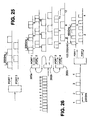
- Fig. 28 illustrates an asymmetric interleaver in accordance with the embodiment described in Fig. 27 wherein two 100Ghz spaced output signal streams are provided having different bandwidths.
Landscapes
- Physics & Mathematics (AREA)
- General Physics & Mathematics (AREA)
- Optics & Photonics (AREA)
- Optical Communication System (AREA)
Applications Claiming Priority (4)
| Application Number | Priority Date | Filing Date | Title |
|---|---|---|---|
| US452877 | 1989-12-19 | ||
| US45287799A | 1999-12-02 | 1999-12-02 | |
| US56639200A | 2000-05-08 | 2000-05-08 | |
| US566392 | 2000-05-08 |
Publications (2)
| Publication Number | Publication Date |
|---|---|
| EP1126293A2 true EP1126293A2 (de) | 2001-08-22 |
| EP1126293A3 EP1126293A3 (de) | 2004-02-25 |
Family
ID=27036918
Family Applications (1)
| Application Number | Title | Priority Date | Filing Date |
|---|---|---|---|
| EP00310572A Withdrawn EP1126293A3 (de) | 1999-12-02 | 2000-11-29 | Optischer Multiplex-/Demultiplex-Schaltkreis |
Country Status (3)
| Country | Link |
|---|---|
| EP (1) | EP1126293A3 (de) |
| CN (1) | CN1308432A (de) |
| CA (1) | CA2326990A1 (de) |
Cited By (4)
| Publication number | Priority date | Publication date | Assignee | Title |
|---|---|---|---|---|
| EP1463224A3 (de) * | 2003-03-26 | 2009-01-07 | Fujitsu Limited | Wellenlängenmultiplexübertragungssystem |
| EP2239874A1 (de) * | 2009-04-08 | 2010-10-13 | Alcatel Lucent | Vorrichtung zum Empfang von Kämmen mit Zwischenkanalfrequenzabstand |
| US8873963B2 (en) | 2012-07-25 | 2014-10-28 | Doron Handelman | Apparatus and methods for generating and receiving optical signals at substantially 100Gb/s and beyond |
| US11063665B2 (en) | 2017-11-30 | 2021-07-13 | Purelifi Limited | Tuneable filter grating for OWC |
Families Citing this family (2)
| Publication number | Priority date | Publication date | Assignee | Title |
|---|---|---|---|---|
| US6901175B2 (en) | 2002-02-28 | 2005-05-31 | Engana Ltd. | Tunable wavelength multiplexer |
| CN107966698B (zh) * | 2017-10-30 | 2021-12-28 | 四川九洲电器集团有限责任公司 | 二次雷达设备及信号处理方法 |
Family Cites Families (3)
| Publication number | Priority date | Publication date | Assignee | Title |
|---|---|---|---|---|
| JPH02193111A (ja) * | 1989-01-23 | 1990-07-30 | Nippon Telegr & Teleph Corp <Ntt> | ファブリ・ペロー形光フィルタ |
| US5835517A (en) * | 1996-10-04 | 1998-11-10 | W. L. Gore & Associates, Inc. | WDM multiplexer-demultiplexer using Fabry-Perot filter array |
| EP0874489A3 (de) * | 1997-04-25 | 2002-05-29 | Jds Fitel Inc. | Verfahren und Vorrichtung für das Demultiplexen optischer Signale |
-
2000
- 2000-11-28 CA CA002326990A patent/CA2326990A1/en not_active Abandoned
- 2000-11-29 EP EP00310572A patent/EP1126293A3/de not_active Withdrawn
- 2000-12-01 CN CN00134467.6A patent/CN1308432A/zh active Pending
Cited By (6)
| Publication number | Priority date | Publication date | Assignee | Title |
|---|---|---|---|---|
| EP1463224A3 (de) * | 2003-03-26 | 2009-01-07 | Fujitsu Limited | Wellenlängenmultiplexübertragungssystem |
| EP2239874A1 (de) * | 2009-04-08 | 2010-10-13 | Alcatel Lucent | Vorrichtung zum Empfang von Kämmen mit Zwischenkanalfrequenzabstand |
| FR2944360A1 (fr) * | 2009-04-08 | 2010-10-15 | Alcatel Lucent | Dispositif optique de reception de peignes a separation frequentielle inter-canaux non conventionnelle |
| US8873963B2 (en) | 2012-07-25 | 2014-10-28 | Doron Handelman | Apparatus and methods for generating and receiving optical signals at substantially 100Gb/s and beyond |
| US9628188B2 (en) | 2012-07-25 | 2017-04-18 | Doron Handelman | Apparatus and methods for generating and receiving optical signals having standard and shifted wavelengths |
| US11063665B2 (en) | 2017-11-30 | 2021-07-13 | Purelifi Limited | Tuneable filter grating for OWC |
Also Published As
| Publication number | Publication date |
|---|---|
| EP1126293A3 (de) | 2004-02-25 |
| CN1308432A (zh) | 2001-08-15 |
| CA2326990A1 (en) | 2001-06-02 |
Similar Documents
| Publication | Publication Date | Title |
|---|---|---|
| US6339474B2 (en) | Interferometric optical device including an optical resonator | |
| US6125220A (en) | Interferometric optical device including a resonant optical cavity | |
| US6275322B1 (en) | Michelson phase shifter interleaver/deinterleavers | |
| US6130971A (en) | Fiber optic dense wavelength division multiplexer with a phase differential method of wavelength separation utilizing a polarization beam splitter and a nonlinear interferometer | |
| US6169626B1 (en) | Optical signal interleaver | |
| US6222958B1 (en) | Optical interleaver/de-interleaver | |
| US6252716B1 (en) | Bulk optic interleaver | |
| EP1024378A2 (de) | Wählerschaltung für optische Kanäle | |
| US6907167B2 (en) | Optical interleaving with enhanced spectral response and reduced polarization sensitivity | |
| CN100430766C (zh) | 光交织器、光去交织器、交织光信号和去交织光信号的方法 | |
| CA2364783A1 (en) | Bidirectional multiplexer and demultiplexer based on a single echelle waveguide grating | |
| US20020126291A1 (en) | Spectrum division multiplexing for high channel count optical networks | |
| EP1016884A2 (de) | Interferometrische optische Vorrichtung mit einem optischen Resonator | |
| WO2000048055A9 (en) | Fiber optic dense wavelength division multiplexer having glass blocks and nonlinear interferometer for separating wavelengths | |
| EP1030480A2 (de) | Konfigurierbare optische Schaltung | |
| EP1126293A2 (de) | Optischer Multiplex-/Demultiplex-Schaltkreis | |
| US6571034B2 (en) | Spectrally-shaped optical components using a wavelength-dispersive element and a reflective array | |
| CN102356340B (zh) | 光学交错器及解交错器 | |
| US20030234935A1 (en) | Bulk optical interferometer | |
| US7418168B2 (en) | Optical add/drop module | |
| US20020094157A1 (en) | Polarization dependent filtering device utilizing a fabry-perot cavity | |
| CA2278358A1 (en) | Asymmetric interleaver/de-interleaver circuit | |
| US6907160B2 (en) | Apparatus for filtering optical signals | |
| JP3358947B2 (ja) | 光合分波装置および光伝送システム | |
| US7924505B1 (en) | Free-space hitlessly switchable optical interleaver |
Legal Events
| Date | Code | Title | Description |
|---|---|---|---|
| PUAI | Public reference made under article 153(3) epc to a published international application that has entered the european phase |
Free format text: ORIGINAL CODE: 0009012 |
|
| AK | Designated contracting states |
Kind code of ref document: A2 Designated state(s): AT BE CH CY DE DK ES FI FR GB GR IE IT LI LU MC NL PT SE TR |
|
| AX | Request for extension of the european patent |
Free format text: AL;LT;LV;MK;RO;SI |
|
| PUAL | Search report despatched |
Free format text: ORIGINAL CODE: 0009013 |
|
| AK | Designated contracting states |
Kind code of ref document: A3 Designated state(s): AT BE CH CY DE DK ES FI FR GB GR IE IT LI LU MC NL PT SE TR |
|
| AX | Request for extension of the european patent |
Extension state: AL LT LV MK RO SI |
|
| RIC1 | Information provided on ipc code assigned before grant |
Ipc: 7G 02B 6/34 B Ipc: 7G 02B 6/293 A |
|
| AKX | Designation fees paid | ||
| REG | Reference to a national code |
Ref country code: DE Ref legal event code: 8566 |
|
| STAA | Information on the status of an ep patent application or granted ep patent |
Free format text: STATUS: THE APPLICATION IS DEEMED TO BE WITHDRAWN |
|
| 18D | Application deemed to be withdrawn |
Effective date: 20040826 |