EP1126310A2 - Lentille de contact multifocale en segments - Google Patents
Lentille de contact multifocale en segments Download PDFInfo
- Publication number
- EP1126310A2 EP1126310A2 EP01201918A EP01201918A EP1126310A2 EP 1126310 A2 EP1126310 A2 EP 1126310A2 EP 01201918 A EP01201918 A EP 01201918A EP 01201918 A EP01201918 A EP 01201918A EP 1126310 A2 EP1126310 A2 EP 1126310A2
- Authority
- EP
- European Patent Office
- Prior art keywords
- lens
- segments
- segment
- distant
- vision
- Prior art date
- Legal status (The legal status is an assumption and is not a legal conclusion. Google has not performed a legal analysis and makes no representation as to the accuracy of the status listed.)
- Withdrawn
Links
Images


Classifications
-
- G—PHYSICS
- G02—OPTICS
- G02C—SPECTACLES; SUNGLASSES OR GOGGLES INSOFAR AS THEY HAVE THE SAME FEATURES AS SPECTACLES; CONTACT LENSES
- G02C7/00—Optical parts
- G02C7/02—Lenses; Lens systems ; Methods of designing lenses
- G02C7/04—Contact lenses for the eyes
-
- G—PHYSICS
- G02—OPTICS
- G02C—SPECTACLES; SUNGLASSES OR GOGGLES INSOFAR AS THEY HAVE THE SAME FEATURES AS SPECTACLES; CONTACT LENSES
- G02C7/00—Optical parts
- G02C7/02—Lenses; Lens systems ; Methods of designing lenses
- G02C7/04—Contact lenses for the eyes
- G02C7/041—Contact lenses for the eyes bifocal; multifocal
- G02C7/042—Simultaneous type
-
- G—PHYSICS
- G02—OPTICS
- G02C—SPECTACLES; SUNGLASSES OR GOGGLES INSOFAR AS THEY HAVE THE SAME FEATURES AS SPECTACLES; CONTACT LENSES
- G02C7/00—Optical parts
- G02C7/02—Lenses; Lens systems ; Methods of designing lenses
- G02C7/04—Contact lenses for the eyes
- G02C7/041—Contact lenses for the eyes bifocal; multifocal
- G02C7/045—Sectorial configuration
-
- Y—GENERAL TAGGING OF NEW TECHNOLOGICAL DEVELOPMENTS; GENERAL TAGGING OF CROSS-SECTIONAL TECHNOLOGIES SPANNING OVER SEVERAL SECTIONS OF THE IPC; TECHNICAL SUBJECTS COVERED BY FORMER USPC CROSS-REFERENCE ART COLLECTIONS [XRACs] AND DIGESTS
- Y10—TECHNICAL SUBJECTS COVERED BY FORMER USPC
- Y10S—TECHNICAL SUBJECTS COVERED BY FORMER USPC CROSS-REFERENCE ART COLLECTIONS [XRACs] AND DIGESTS
- Y10S425/00—Plastic article or earthenware shaping or treating: apparatus
- Y10S425/808—Lens mold
Definitions
- presbyopia and presbyopes have in the past relied upon spectacles or other lenses having a number of different zones with different optical powers to which the wearer can shift his vision in order to find the appropriate optical power for the object or objects upon which the observer wishes to focus.
- the contact lens working in conjunction with the natural lens, forms an image on the retina of the eye by focusing light incident on each part of the cornea from different field angles onto each part of the retina in order to form the image. For instance, as the pupil contracts in response to brighter light, the image on the retina does not shrink but rather light coming through a smaller portion of the lens is used to construct the entire image.
- Prior art lenses using zones of a different refractive focal lengths were typically theoretical designs and not manufactured. This failure to realize an actual product is due to the inability to manufacture the type of lenses conceived.
- the production of contact lenses as well as intraocular lenses is performed by spin casting or precision lathe cutting. These processes produce radially symmetric lenses upon which it is extremely difficult to effect areas having different focal lengths because machining different curvatures around the lens is impossible.
- One attempt known in the art to provide a method of compensating for presbyopia without complex lens manufacture is known as "monovision".
- monovision a patient is fitted with one contact lens for distant vision in one eye and a second contact lens for near vision in the other eye.
- Another approach to producing a multifocal corrective eye lens involves the use of diffractive optics.
- One of the shortcomings of this approach as with previously described types of multifocal lenses using radially symmetric, concentric near and far distance zones has been a deficiency in near vision, particularly at low light levels.
- a diffractive design only about 40% of the light incident on the lens is used for near vision with another 40% being used for far vision. The remaining 20% is not used for either near or far vision, but rather is lost to higher orders of diffraction and scatter effect. This represents the best theoretical case and in manufacturing reality even less light is available due to manufacturing difficulties.
- Difficulty of manufacture in general represents another shortcoming of diffractive lenses since the diffractive surface must be to tolerances on the order of the wavelength of light.
- the lens surface molds are separated into interchangeable segments which can be assembled to provide a segmented multifocal lens which is then used to mold a lens using the lens mold surface.
- a non-oriented, multifocal refractive lens made of a plurality of segments having at least two different optical powers to effectively focus light on the retina of the eye and provide near and distant vision.
- a first optical power is provided on a first set of segments to provide distance vision while a second set of segments provides a second optical power to provide near vision.
- the optical powers may be provided by a variation in thickness or curvature of the refractive lens material. These segments can be arranged so that the ratio of the areas of each optical power remain constant despite the changing diameter of the pupil.
- the boundaries may either be line segments or curved arcuate paths.
- each focal length effectively exists about the entire lens so that orientation of the lens is not critical.
- At least one set of segments with a common optical power has an aspherical surface curvature.
- This aspherical lens surface allows the curvatures of the segments to be matched along their boundaries so as to be smooth and essentially continuous.
- a further aspect of the invention is a method of producing a multifocal lens with a plurality of segments as described above.
- This type of lens may be made by taking lens surface molds for different optical powers and separating these lens surfaces into segments along a path from the center of the surface mold to the circumferential edge so that the segments are similarly sized and interchangeable.
- a multifocal lens mold can then be assembled from the segments of the first and second lens surface molds fitted together from that composite lens surface mold.
- a segmented multifocal lens can then be molded and subsequent to the molding the lens segments separated for later reuse.
- Another aspect of the invention is the use of a particular arcuate path to divide the segments, such that the step height between segments is minimized.
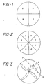
- Figure 1 is a plan view of an embodiment of the invention.
- Figure 2 is a plan view of another version of this embodiment.
- Figure 3 is a plan view of another embodiment of the invention.
- Figure 4 is a plan view of another version of the embodiment of Fig. 3.
- Figure 5 is an alternate embodiment of the present invention.
- Figure 6 is a graph showing a comparison between the lens surface height position of the optical power segments of a bifocal contact lens, one an aspheric and the other spherical for a contact lens made according to the present invention.
- Figure 7 is a graph showing the magnified difference between the two groups of Fig. 6.
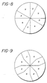
- Figure 8 is a plan view of an alternate embodiment of the invention where the ratio of the surface area between the near and distant vision is unequal and of a consistent ratio concentricly from the center to the circumference of the lens.
- Figure 9 is a plan view of an alternate embodiment of a lens having substantially equal areas of near and distant focal lengths near the center of the lens and an unequal ratio of areas of near and distant focal length toward the periphery of the lens.
- the invention is shown in its simplest form, consisting of alternating near and distant portions.
- a fundamental advantage of this invention is that the lens shown has no weighting, ballasting or prism used to orient the lens in a particular orientation.
- Another aspect of this embodiment is that the area of near and distant focal lengths are equal and independent of pupil size. This pupil size independence can be realized by recognizing that the ratio of areas for near and distant vision remains the same for any circle within the lens concentric with the lens.
- a lens is shown similar to the lens Figure 1 having equal areas of near and distant focal length. Again, there is no weighting, prisming or ballasting of the lens, but a larger number of segments which is potentially more difficult to manufacture, yields improved vision because of a more uniform distribution of near and far focal points over the entire lens.
- the wearer of the lens according to the present invention can not only have acceptable vision at both distant and near focal lengths, but also attains a fair degree of steroscopic vision wherein depth perception is achieved.
- the lens of the present invention has the advantage that the ratio between the distant and near portion of the lens can either be set at each radius or can be a controlled function of the pupil size.
- the advantage of using an aspheric surface of either near or distant portion, or on both, is that the aspheric shapes allow a design to be fabricated which has a uniform and equal lenticular junction and edge thickness. This is not possible with spherical sections. Although it is possible to design a lens according to the present invention with spherical sections that would meet optical requirements, the use of the aspheric surfaces on either one or both of the focal lengths areas minimizes step height difference between the surfaces and irritation to the eye.
- placing the optical surface on the front of the lens eliminates cornea insult, injury and debris entrapment.
- spherical surfaces is totally acceptable from the optical standpoint and can be utilized in certain embodiments, particularly with placement of the optical surface on the front of the lens against the eyelid rather than against the cornea.
- Using an arcuate boundary between the segments decreases the step height by defining a path that is at an angle to the gradient between the two segment heights.
- the arc is drawn with one end of the arc at the lens center and the other at the edge of the optic zone with the center of curvature placed along the perpendicular FG of the line connecting the two end points of the arc chord, CB.
- Arc chord, CB is a portion of a circle having a center point along line segment FG and radius r as shown in figure 3.
- a typical arc segment would be one where the radius is longer than the arc chord, for example, a ratio of two to one between the arc radius and the chord bisector. Ratios of two to one or greater would be expected to yield good results, although a ratio of less than two to one may be used, with the limiting case being a semicircle having its midpoint along line segment CB.
- Figure 4 shows another embodiment utilizing arcuate boundaries in this embodiment with the advantage of having additional near and distant segments.
- an embodiment of the invention is shown maintaining a substantially constant ratio of distant and near lens areas independent of pupil size. Rather than using segments with boundaries from the center to the circumference, the lens is divided into line segment chords across the lens.
- Figure 6 showing a comparison between the segment surface position for the distant focal portion of the lens and the near focal portion for a segmented aspheric bifocal lens made according to the embodiment shown in Fig. 1.
- a lens is shown having a distant prescription of -5.25 diopters with a near vision portion add of +1.50 diopters, yielding a near portion vision having an absolute optical power of -3.75.
- the step height difference between the segments is less for the aspheric surface than for the spherical lens surfaces. Given are the height of the far focal surface, the near focal surface and the difference between these two at the boundary for both aspherical and the spherical lens design as a function of position from the center of the lens.
- the constant K associated with a particular lens surface curvature is an important selection process.
- the ⁇ value used for establishing the aspherical curve for the near and distant vision surfaces in the aspheric lens design are different.
- the ⁇ value for the distant portion is -0.2 and the ⁇ value for the near portion is -1.06.
- FIG. 7 there is shown in graphic form the step height difference between segments using aspherical lens surfaces.
- the step height is small in any case.
- halfway between the center and the edge about 3
- halfway between the center and the edge about 3 millimeters from the center of the lens, there is a step of about .008 millimeters, for an improvement of about .011mm.
- the improvement is .034mm.
- the decreased step differential and decreased center thickness allows increased local oxygenation of the cornea.
- the arcuate boundary between segments of a multifocal lens reduce the step height between segments by traversing a path at a substantial angle to the gradient formed by the two different heights of lens material rather than having a boundary that substantially follows the gradient between the two heights of the lens segments.
- a lens of the above type is preferably manufactured by molding.
- the molding process preferred is that described in U.S. Patents 4,495,313 and 4,889,664.
- the lens surface mold to be made is not made on the surface that will immediately mold the lens but is made one step removed on a metal surface which is used to make a plastic styrene mold which is then used to make the lens.
- the word "mold” is used to refer to any previous generation of mold used in making the lens, that is not only the surfaces used to make lens itself, but the surfaces used to make the molds that ultimately make the lens.
- the metal molds containing the multifocal segmented surfaces are made by selecting the appropriate lens powers from conventional spherical or aspherical molds. In the above example, these would be the surfaces corresponding to the -5.25 diopters and the surface corresponding to a -3.75 diopters.
- Molds produced in this way can be fitted together to produce a segmented multifocal lens and bonded to produce a surface that can be used to make a mold that ultimately makes the contact lens. These segments may be bonded together in making the contact lens mold and then separated for later reuse.
- the ratio between the area of near and distant focal length can be made to be a function of pupil diameter.
- the pupil diameter is small, there is an equal area of near and distant focal lengths.
- the ratio of near to distant focal length increase as can be readily seen and appreciated by one skilled in the art. It is easy to tailor not only the ratio of areas between near and distant focal length but also the point at which a transition is made and any of these configurations are easily manufactured by molding after the first lens mold is constructed as described above.
- a lens designed according to Fig. 1 was constructed for a presbyopic patient with the distant segment powers corresponding to his distance prescription and with an add power of +2.00 diopters.
- the actual lens construction was -5.50 diopters/minus -3.50 diopters of alternating spherical segments.
- Stereopsis was measured to a small as 40 arc seconds. This number represent a clinically normal level of stereopsis found in emmetropes as well corrected ametropes, including presbyopes wearing corrective spectacles.
Landscapes
- Health & Medical Sciences (AREA)
- Ophthalmology & Optometry (AREA)
- Physics & Mathematics (AREA)
- General Health & Medical Sciences (AREA)
- General Physics & Mathematics (AREA)
- Optics & Photonics (AREA)
- Eyeglasses (AREA)
- Prostheses (AREA)
- Casting Or Compression Moulding Of Plastics Or The Like (AREA)
- Lenses (AREA)
- Moulds For Moulding Plastics Or The Like (AREA)
Applications Claiming Priority (4)
| Application Number | Priority Date | Filing Date | Title |
|---|---|---|---|
| US07/728,903 US5198844A (en) | 1991-07-10 | 1991-07-10 | Segmented multifocal contact lens |
| US728903 | 1991-07-10 | ||
| EP92306303A EP0522852A1 (fr) | 1991-07-10 | 1992-07-09 | Lentille de contact multifocale en segments et méthode de fabrication |
| EP96203351A EP0764870B1 (fr) | 1991-07-10 | 1992-07-09 | Lentille de contact en segments |
Related Parent Applications (1)
| Application Number | Title | Priority Date | Filing Date |
|---|---|---|---|
| EP96203351A Division EP0764870B1 (fr) | 1991-07-10 | 1992-07-09 | Lentille de contact en segments |
Publications (2)
| Publication Number | Publication Date |
|---|---|
| EP1126310A2 true EP1126310A2 (fr) | 2001-08-22 |
| EP1126310A3 EP1126310A3 (fr) | 2001-09-05 |
Family
ID=24928736
Family Applications (3)
| Application Number | Title | Priority Date | Filing Date |
|---|---|---|---|
| EP96203351A Expired - Lifetime EP0764870B1 (fr) | 1991-07-10 | 1992-07-09 | Lentille de contact en segments |
| EP01201918A Withdrawn EP1126310A3 (fr) | 1991-07-10 | 1992-07-09 | Lentille de contact multifocale en segments |
| EP92306303A Ceased EP0522852A1 (fr) | 1991-07-10 | 1992-07-09 | Lentille de contact multifocale en segments et méthode de fabrication |
Family Applications Before (1)
| Application Number | Title | Priority Date | Filing Date |
|---|---|---|---|
| EP96203351A Expired - Lifetime EP0764870B1 (fr) | 1991-07-10 | 1992-07-09 | Lentille de contact en segments |
Family Applications After (1)
| Application Number | Title | Priority Date | Filing Date |
|---|---|---|---|
| EP92306303A Ceased EP0522852A1 (fr) | 1991-07-10 | 1992-07-09 | Lentille de contact multifocale en segments et méthode de fabrication |
Country Status (27)
| Country | Link |
|---|---|
| US (2) | US5198844A (fr) |
| EP (3) | EP0764870B1 (fr) |
| JP (1) | JP3274713B2 (fr) |
| KR (1) | KR930002850A (fr) |
| CN (1) | CN1030480C (fr) |
| AT (1) | ATE233411T1 (fr) |
| AU (1) | AU650550B2 (fr) |
| BR (1) | BR9202524A (fr) |
| CA (1) | CA2073536C (fr) |
| DE (1) | DE69232936T2 (fr) |
| FI (1) | FI923173A7 (fr) |
| GR (1) | GR1002024B (fr) |
| GT (1) | GT199200040A (fr) |
| HN (1) | HN1992004968A (fr) |
| HU (1) | HUT63007A (fr) |
| IE (2) | IE922242A1 (fr) |
| IL (1) | IL102029A (fr) |
| MX (1) | MX9204025A (fr) |
| NO (1) | NO922691L (fr) |
| NZ (1) | NZ242910A (fr) |
| RO (1) | RO111631B (fr) |
| RU (1) | RU2099760C1 (fr) |
| SG (1) | SG48722A1 (fr) |
| TW (1) | TW226975B (fr) |
| UY (1) | UY23444A1 (fr) |
| YU (1) | YU59992A (fr) |
| ZA (1) | ZA925141B (fr) |
Cited By (3)
| Publication number | Priority date | Publication date | Assignee | Title |
|---|---|---|---|---|
| WO2003054616A3 (fr) * | 2001-12-20 | 2003-12-18 | Johnson & Johnson Vision Care | Lentilles ophtalmologiques a foyer progressif |
| US7044597B2 (en) | 2003-12-16 | 2006-05-16 | Bausch & Lomb Incorporated | Multifocal contact lens and method of manufacture thereof |
| WO2023073339A1 (fr) * | 2021-10-27 | 2023-05-04 | Coopervision International Limited | Lentilles ophtalmiques |
Families Citing this family (64)
| Publication number | Priority date | Publication date | Assignee | Title |
|---|---|---|---|---|
| CZ282423B6 (cs) * | 1992-01-28 | 1997-07-16 | Johnson & Johnson Vision Products, Inc. | Multifokální refrakční čočka a způsob její výroby |
| US5748282A (en) * | 1993-01-27 | 1998-05-05 | Pilkington Barnes Hind, Inc. | Multifocal contact lens |
| GB9306424D0 (en) * | 1993-03-27 | 1993-05-19 | Pilkington Visioncare Inc | Contact lens designed to accommodate and correct for the effects of presbyopia |
| US5408281A (en) * | 1993-04-26 | 1995-04-18 | Ciba-Geigy | Multifocal contact lens |
| US5502518A (en) * | 1993-09-09 | 1996-03-26 | Scient Optics Inc | Asymmetric aspheric contact lens |
| US5517260A (en) * | 1994-03-28 | 1996-05-14 | Vari-Site, Inc. | Ophthalmic lens having a progressive multifocal zone and method of manufacturing same |
| CN1048447C (zh) * | 1994-04-14 | 2000-01-19 | 陈钦仁 | 单镜片双焦距镜片的模具制造方法 |
| HUP9601126A3 (en) * | 1995-05-04 | 1999-10-28 | Johnson & Johnson Vision Prod | Concentric, aspheric, multifocal lens |
| US5929969A (en) * | 1995-05-04 | 1999-07-27 | Johnson & Johnson Vision Products, Inc. | Multifocal ophthalmic lens |
| WO1996039106A1 (fr) * | 1995-06-06 | 1996-12-12 | Scientific Optics, Inc. | Cristallin artificiel bifocal et asymetrique |
| US5724258A (en) * | 1996-05-09 | 1998-03-03 | Johnson & Johnson Vision Products, Inc. | Neural network analysis for multifocal contact lens design |
| US5835187A (en) * | 1996-11-22 | 1998-11-10 | Wilmington Partners L.P. | Aspheric multifocal contact lens having concentric front surface |
| US5980040A (en) * | 1997-06-30 | 1999-11-09 | Wesley Jessen Corporation | Pinhole lens and contact lens |
| CA2306864C (fr) * | 1998-03-04 | 2012-05-15 | Visx, Incorporated | Systeme de traitement laser de la presbytie en utilisant une image decentree |
| US6457826B1 (en) | 1998-08-06 | 2002-10-01 | John B. W. Lett | Multifocal aspheric lens |
| AU2365300A (en) * | 1998-12-16 | 2000-07-03 | Wesley-Jessen Corporation | Multifocal contact lens with aspheric surface |
| US6619799B1 (en) * | 1999-07-02 | 2003-09-16 | E-Vision, Llc | Optical lens system with electro-active lens having alterably different focal lengths |
| RU2186417C2 (ru) * | 2000-02-22 | 2002-07-27 | Институт автоматики и электрометрии СО РАН | Дифракционная интраокулярная линза |
| GB2364136B (en) * | 2000-06-29 | 2004-11-17 | Brian David Cantor | Multifocal contact lenses |
| US7293871B2 (en) * | 2000-11-27 | 2007-11-13 | Ophthonix, Inc. | Apparatus and method of correcting higher-order aberrations of the human eye |
| US6813082B2 (en) | 2000-11-27 | 2004-11-02 | Ophthonix, Inc. | Wavefront aberrator and method of manufacturing |
| US7217375B2 (en) * | 2001-06-04 | 2007-05-15 | Ophthonix, Inc. | Apparatus and method of fabricating a compensating element for wavefront correction using spatially localized curing of resin mixtures |
| US7434931B2 (en) | 2001-10-25 | 2008-10-14 | Ophthonix | Custom eyeglass manufacturing method |
| US6682195B2 (en) * | 2001-10-25 | 2004-01-27 | Ophthonix, Inc. | Custom eyeglass manufacturing method |
| US6712466B2 (en) * | 2001-10-25 | 2004-03-30 | Ophthonix, Inc. | Eyeglass manufacturing method using variable index layer |
| US6986578B2 (en) * | 2003-01-30 | 2006-01-17 | Johnson & Johnson Vision Care, Inc. | Multifocal ophthalmic lenses |
| KR100478281B1 (ko) * | 2003-03-20 | 2005-03-25 | 조현수 | 근용 단초점 이중렌즈 |
| US7063422B2 (en) * | 2003-04-16 | 2006-06-20 | Novartis Ag | Multifocal ophthalmic lens |
| US6951391B2 (en) * | 2003-06-16 | 2005-10-04 | Apollo Optical Systems Llc | Bifocal multiorder diffractive lenses for vision correction |
| US6899425B2 (en) * | 2003-10-28 | 2005-05-31 | Johnson & Johnson Vision Care, Inc. | Multifocal ophthalmic lenses |
| US20050260388A1 (en) * | 2004-05-21 | 2005-11-24 | Lai Shui T | Apparatus and method of fabricating an ophthalmic lens for wavefront correction using spatially localized curing of photo-polymerization materials |
| US7156516B2 (en) * | 2004-08-20 | 2007-01-02 | Apollo Optical Systems Llc | Diffractive lenses for vision correction |
| US7025456B2 (en) * | 2004-08-20 | 2006-04-11 | Apollo Optical Systems, Llc | Diffractive lenses for vision correction |
| US7503652B2 (en) * | 2006-06-29 | 2009-03-17 | Johnson & Johnson Vision Care, Inc. | Translating multifocal ophthalmic lenses |
| AR062067A1 (es) * | 2006-07-17 | 2008-10-15 | Novartis Ag | Lentes de contacto toricas con perfil de potencia optica controlado |
| US7572007B2 (en) * | 2006-08-02 | 2009-08-11 | Alcon, Inc. | Apodized diffractive IOL with frustrated diffractive region |
| US20090157179A1 (en) * | 2007-12-11 | 2009-06-18 | Pinto Candido D | Ophthalmic Lenses Providing an Extended Depth of Field |
| US7753521B2 (en) * | 2008-03-31 | 2010-07-13 | Johnson & Johnson Vision Care, Inc. | Lenses for the correction of presbyopia and methods of designing the lenses |
| US8331048B1 (en) | 2009-12-18 | 2012-12-11 | Bausch & Lomb Incorporated | Methods of designing lenses having selected depths of field |
| US8531783B2 (en) | 2010-02-09 | 2013-09-10 | Xceed Imaging Ltd. | Imaging method and system for imaging with extended depth of focus |
| JP5984263B2 (ja) | 2010-03-03 | 2016-09-06 | ブライアン・ホールデン・ビジョン・インスティチュートBrien Holden Vision Institute | 近視の眼のためのコンタクトレンズおよび近視を処置する方法 |
| CN104181701B (zh) * | 2013-05-24 | 2016-04-13 | 亨泰光学股份有限公司 | 镜片装置及视力控制方法 |
| TWI493241B (zh) | 2013-05-24 | 2015-07-21 | Hiline Optical Co Ltd | 鏡片裝置及視力控制方法 |
| RU2554220C2 (ru) * | 2013-10-23 | 2015-06-27 | Леонтьева Галина Дмитриевна | Имплантат для введения в роговичный карман человеческого глаза с целью коррекции аномалий рефракции |
| US9995946B2 (en) | 2014-06-13 | 2018-06-12 | Pegavision Corporation | Toric lens |
| US12127934B2 (en) | 2014-09-09 | 2024-10-29 | Staar Surgical Company | Method of Providing Modified Monovision to a Subject with a First Lens and a Second Lens |
| KR102249250B1 (ko) | 2014-09-09 | 2021-05-07 | 스타 서지컬 컴퍼니 | 확장된 피사계 심도 및 향상된 원거리 시력의 안과용 임플란트 |
| JP6500484B2 (ja) * | 2015-02-19 | 2019-04-17 | 株式会社ニデック | 多焦点眼内レンズ |
| KR101578327B1 (ko) * | 2015-06-04 | 2015-12-16 | 구오섭 | 노안용 콘택트렌즈 |
| CN105589215B (zh) * | 2016-03-08 | 2018-09-14 | 李国荣 | 热塑性内渐进镜片及其加工方法 |
| ES2912080T3 (es) | 2016-03-09 | 2022-05-24 | Staar Surgical Co | Implantes oftálmicos con mayor profundidad de campo y agudeza visual mejorada a distancia |
| KR101870142B1 (ko) * | 2016-08-12 | 2018-06-25 | 이성준 | 노안용 콘택트렌즈 |
| EP3713529B1 (fr) * | 2017-11-24 | 2025-01-08 | Université de Montréal | Méthode de fabrication d'une lentille corrective pour la gestion de croissance de la longueur axiale oculaire dans le contexte d'une évolution d'une erreur de réfraction |
| CN108346737B (zh) * | 2018-02-08 | 2021-08-06 | 嘉兴晶控电子有限公司 | 压电石英基片生产工艺 |
| KR102560250B1 (ko) | 2018-08-17 | 2023-07-27 | 스타 서지컬 컴퍼니 | 나노 구배의 굴절률을 나타내는 중합체 조성물 |
| CN109031696B (zh) * | 2018-08-20 | 2020-06-05 | 赵佩韬 | 基于周边微透镜的视力控制镜片及眼镜 |
| CN110142899B (zh) * | 2019-06-11 | 2021-12-14 | 丹阳市正阳光学有限公司 | 一线双光棱镜片模具的制造工艺 |
| FR3097980B1 (fr) | 2019-06-28 | 2022-08-19 | Laurent Galinier | Lentille multifocale à aberration de coma |
| CN110509117B (zh) * | 2019-09-04 | 2024-07-23 | 比耐思健康科技(浙江)有限公司 | 镜片磨制方法及镜片 |
| US11754858B2 (en) | 2020-04-30 | 2023-09-12 | Coopervision International Limited | Multifocal ophthalmic lens and related methods |
| US11762220B2 (en) | 2020-04-30 | 2023-09-19 | Coopervision International Limited | Multifocal ophthalmic lenses and related methods |
| CA3234381A1 (fr) | 2021-10-04 | 2023-04-13 | Staar Surgical Company | Implants ophtalmiques de correction de la vision avec une optique accordable, et procedes de fabrication et d'utilisation associes |
| US12422696B2 (en) | 2022-10-31 | 2025-09-23 | Coopervision International Limited | Ophthalmic lenses and methods relating thereto |
| WO2026021664A1 (fr) | 2024-07-23 | 2026-01-29 | Rayner Intraocular Lenses Limited | Lentille intraoculaire à multiples zones en spirale |
Family Cites Families (23)
| Publication number | Priority date | Publication date | Assignee | Title |
|---|---|---|---|---|
| US1955047A (en) * | 1931-12-03 | 1934-04-17 | Howard D Beach | Spectacle lens |
| US2254440A (en) * | 1939-08-18 | 1941-09-02 | American Optical Corp | Multifocal lens and method of making same |
| US3109696A (en) * | 1962-05-15 | 1963-11-05 | American Optical Corp | Method of making plastic lenses |
| US3455668A (en) * | 1966-05-25 | 1969-07-15 | American Optical Corp | Method of making optical coupling devices |
| US3555126A (en) * | 1967-12-19 | 1971-01-12 | Abraham Gitson | Method of making a mold and molding a bifocal lens |
| US3594075A (en) * | 1968-10-14 | 1971-07-20 | David Jean Smith | Bifocal ophthalmic lens |
| US3829536A (en) * | 1971-04-05 | 1974-08-13 | Humphrey Res Ass | Method of forming an optical element of reduced thickness |
| CA964908A (en) * | 1971-06-11 | 1975-03-25 | E. I. Du Pont De Nemours And Company | Low refractive index contact lenses |
| US3931373A (en) * | 1971-12-21 | 1976-01-06 | J. O. Beattie Research Company | Replication processes for producing plastic optical components |
| US4279401A (en) * | 1980-05-30 | 1981-07-21 | American Optical Corporation | Apparatus and method for making cast ophthalmic lenses |
| US4495313A (en) | 1981-04-30 | 1985-01-22 | Mia Lens Production A/S | Preparation of hydrogel for soft contact lens with water displaceable boric acid ester |
| EP0107444B1 (fr) * | 1982-10-13 | 1990-06-27 | N.G. Trustees And Nominees Limited | Lentilles de contact bifocaux |
| DE3246306A1 (de) * | 1982-12-14 | 1984-06-14 | Titmus Eurocon Kontaktlinsen Gmbh & Co Kg, 8750 Aschaffenburg | Bifokallinse vom bivisuellen typ |
| FR2573876A1 (fr) * | 1984-11-26 | 1986-05-30 | Vinzia Francis | Lentille multifocale, procede de preparation de cette lentille et utilisation comme lentille de contact ou comme implant intra-oculaire pour remplacer le cristallin |
| DE3617363A1 (de) * | 1986-05-23 | 1987-11-26 | Schott Glaswerke | Verfahren zur herstellung von zylindersymmetrischen koerpern mit vorgegebenem radialem gefaelle physikalischer materialeigenschaften und anwendungen |
| US4798609A (en) * | 1987-08-24 | 1989-01-17 | Grendahl Dennis T | Radially segmented zone of focus artificial lens |
| US4923296A (en) * | 1988-07-14 | 1990-05-08 | Erickson Paul M | Oriented simultaneous vision bifocal contact lenses or the like utilizing introaocular suppression of blur |
| US4889664A (en) | 1988-11-25 | 1989-12-26 | Vistakon, Inc. | Method of forming shaped hydrogel articles including contact lenses |
| AU7130391A (en) * | 1990-03-08 | 1991-09-12 | Breger, Joseph Laurence | Multifocal simultaneous vision lenses |
| US5096285A (en) * | 1990-05-14 | 1992-03-17 | Iolab Corporation | Multifocal multizone diffractive ophthalmic lenses |
| US5050981A (en) | 1990-07-24 | 1991-09-24 | Johnson & Johnson Vision Products, Inc. | Lens design method and resulting aspheric lens |
| US5173723A (en) * | 1990-10-02 | 1992-12-22 | Volk Donald A | Aspheric ophthalmic accommodating lens design for intraocular lens and contact lens |
| US5141678A (en) * | 1990-10-10 | 1992-08-25 | Blum Ronald D | Method for forming disposable molds for producing optical quality lenses |
-
1991
- 1991-07-10 US US07/728,903 patent/US5198844A/en not_active Expired - Lifetime
-
1992
- 1992-01-04 TW TW081104397A patent/TW226975B/zh not_active IP Right Cessation
- 1992-05-26 NZ NZ242910A patent/NZ242910A/en unknown
- 1992-05-26 GR GR920100213A patent/GR1002024B/el unknown
- 1992-05-27 IL IL10202992A patent/IL102029A/en not_active IP Right Cessation
- 1992-06-10 YU YU59992A patent/YU59992A/sh unknown
- 1992-07-01 AU AU19411/92A patent/AU650550B2/en not_active Expired
- 1992-07-06 HN HN1992004968A patent/HN1992004968A/es unknown
- 1992-07-07 JP JP20181492A patent/JP3274713B2/ja not_active Expired - Lifetime
- 1992-07-08 BR BR929202524A patent/BR9202524A/pt not_active Application Discontinuation
- 1992-07-08 NO NO92922691A patent/NO922691L/no unknown
- 1992-07-09 RO RO92-0943A patent/RO111631B/ro unknown
- 1992-07-09 EP EP96203351A patent/EP0764870B1/fr not_active Expired - Lifetime
- 1992-07-09 RU SU925052351A patent/RU2099760C1/ru active
- 1992-07-09 IE IE224292A patent/IE922242A1/en not_active IP Right Cessation
- 1992-07-09 MX MX9204025A patent/MX9204025A/es not_active IP Right Cessation
- 1992-07-09 KR KR1019920012204A patent/KR930002850A/ko not_active Abandoned
- 1992-07-09 CA CA002073536A patent/CA2073536C/fr not_active Expired - Lifetime
- 1992-07-09 FI FI923173A patent/FI923173A7/fi not_active Application Discontinuation
- 1992-07-09 EP EP01201918A patent/EP1126310A3/fr not_active Withdrawn
- 1992-07-09 ZA ZA925141A patent/ZA925141B/xx unknown
- 1992-07-09 UY UY23444A patent/UY23444A1/es not_active IP Right Cessation
- 1992-07-09 SG SG1996000618A patent/SG48722A1/en unknown
- 1992-07-09 AT AT96203351T patent/ATE233411T1/de not_active IP Right Cessation
- 1992-07-09 IE IE20030912A patent/IE20030912A1/en not_active IP Right Cessation
- 1992-07-09 EP EP92306303A patent/EP0522852A1/fr not_active Ceased
- 1992-07-09 DE DE69232936T patent/DE69232936T2/de not_active Expired - Lifetime
- 1992-07-10 HU HU9202287A patent/HUT63007A/hu unknown
- 1992-07-10 CN CN92105881A patent/CN1030480C/zh not_active Expired - Lifetime
- 1992-07-16 GT GT199200040A patent/GT199200040A/es unknown
-
1994
- 1994-08-01 US US08/283,654 patent/US5507979A/en not_active Expired - Lifetime
Cited By (5)
| Publication number | Priority date | Publication date | Assignee | Title |
|---|---|---|---|---|
| WO2003054616A3 (fr) * | 2001-12-20 | 2003-12-18 | Johnson & Johnson Vision Care | Lentilles ophtalmologiques a foyer progressif |
| US7044597B2 (en) | 2003-12-16 | 2006-05-16 | Bausch & Lomb Incorporated | Multifocal contact lens and method of manufacture thereof |
| WO2023073339A1 (fr) * | 2021-10-27 | 2023-05-04 | Coopervision International Limited | Lentilles ophtalmiques |
| CN118159898A (zh) * | 2021-10-27 | 2024-06-07 | 库博光学国际有限公司 | 眼用镜片 |
| EP4528362A1 (fr) * | 2021-10-27 | 2025-03-26 | CooperVision International Limited | Lentilles ophtalmiques |
Also Published As
Similar Documents
| Publication | Publication Date | Title |
|---|---|---|
| EP0764870B1 (fr) | Lentille de contact en segments | |
| EP0553959B1 (fr) | Lentille de contact multifocale segmentée à région centrale non divisée | |
| US5512220A (en) | Method of making a clear axis, segmented multifocal ophthalmic lens | |
| IE84161B1 (en) | Segmented multifocal contact lens | |
| EP1212652B1 (fr) | Lentilles bifocales | |
| CA2175632C (fr) | Verres toriques multifocaux combines | |
| US5106180A (en) | Multifocal ophthalmic lens | |
| US4890913A (en) | Zoned multi-focal contact lens | |
| US6511178B1 (en) | Multifocal ophthalmic lenses and processes for their production | |
| US7025455B2 (en) | Multifocal contact lenses having a pinhole | |
| JPH0947463A (ja) | 中間光学的屈折力を備えた多焦点レンズ | |
| EP0741315A2 (fr) | Lentilles à des anneaux concentriques avec des angles entre des segments annulaires adjacentes minimalisés | |
| HK1002597B (en) | Segmented multifocal contact lens | |
| JPH06214198A (ja) | 多焦点コンタクトレンズおよびその製造方法 | |
| GB1569766A (en) | Multifocal ophthalmic lens |
Legal Events
| Date | Code | Title | Description |
|---|---|---|---|
| PUAI | Public reference made under article 153(3) epc to a published international application that has entered the european phase |
Free format text: ORIGINAL CODE: 0009012 |
|
| PUAL | Search report despatched |
Free format text: ORIGINAL CODE: 0009013 |
|
| AC | Divisional application: reference to earlier application |
Ref document number: 764870 Country of ref document: EP Ref document number: 522852 Country of ref document: EP |
|
| AK | Designated contracting states |
Kind code of ref document: A2 Designated state(s): AT BE CH DE DK ES FR GB IT LI LU NL PT SE Kind code of ref document: A2 Designated state(s): DE FR GB IT |
|
| AK | Designated contracting states |
Kind code of ref document: A3 Designated state(s): AT BE CH DE DK ES FR GB IT LI LU NL PT SE |
|
| RIN1 | Information on inventor provided before grant (corrected) |
Inventor name: SCRIVENER, JOHN Inventor name: MENEZES, EDGAR Inventor name: ROFFMAN, JEFFREY H. |
|
| 17P | Request for examination filed |
Effective date: 20020226 |
|
| AKX | Designation fees paid |
Free format text: DE FR GB IT |
|
| GRAP | Despatch of communication of intention to grant a patent |
Free format text: ORIGINAL CODE: EPIDOSNIGR1 |
|
| STAA | Information on the status of an ep patent application or granted ep patent |
Free format text: STATUS: THE APPLICATION IS DEEMED TO BE WITHDRAWN |
|
| 18D | Application deemed to be withdrawn |
Effective date: 20040202 |