EP1126486A1 - Mehrpoliger Schalter - Google Patents
Mehrpoliger Schalter Download PDFInfo
- Publication number
- EP1126486A1 EP1126486A1 EP01400347A EP01400347A EP1126486A1 EP 1126486 A1 EP1126486 A1 EP 1126486A1 EP 01400347 A EP01400347 A EP 01400347A EP 01400347 A EP01400347 A EP 01400347A EP 1126486 A1 EP1126486 A1 EP 1126486A1
- Authority
- EP
- European Patent Office
- Prior art keywords
- contacts
- contact
- movable
- positionable
- switch
- Prior art date
- Legal status (The legal status is an assumption and is not a legal conclusion. Google has not performed a legal analysis and makes no representation as to the accuracy of the status listed.)
- Withdrawn
Links
- 230000000295 complement effect Effects 0.000 claims description 8
- 230000005405 multipole Effects 0.000 description 17
- 230000007935 neutral effect Effects 0.000 description 9
- 150000001875 compounds Chemical class 0.000 description 3
- 238000004519 manufacturing process Methods 0.000 description 3
- 230000015572 biosynthetic process Effects 0.000 description 1
- 238000009434 installation Methods 0.000 description 1
Images


Classifications
-
- H—ELECTRICITY
- H01—ELECTRIC ELEMENTS
- H01H—ELECTRIC SWITCHES; RELAYS; SELECTORS; EMERGENCY PROTECTIVE DEVICES
- H01H1/00—Contacts
- H01H1/12—Contacts characterised by the manner in which co-operating contacts engage
- H01H1/14—Contacts characterised by the manner in which co-operating contacts engage by abutting
- H01H1/34—Contacts characterised by the manner in which co-operating contacts engage by abutting with provision for adjusting position of contact relative to its co-operating contact
-
- H—ELECTRICITY
- H01—ELECTRIC ELEMENTS
- H01H—ELECTRIC SWITCHES; RELAYS; SELECTORS; EMERGENCY PROTECTIVE DEVICES
- H01H71/00—Details of the protective switches or relays covered by groups H01H73/00 - H01H83/00
- H01H71/002—Details of the protective switches or relays covered by groups H01H73/00 - H01H83/00 with provision for switching the neutral conductor
-
- H—ELECTRICITY
- H01—ELECTRIC ELEMENTS
- H01H—ELECTRIC SWITCHES; RELAYS; SELECTORS; EMERGENCY PROTECTIVE DEVICES
- H01H1/00—Contacts
- H01H1/12—Contacts characterised by the manner in which co-operating contacts engage
- H01H1/14—Contacts characterised by the manner in which co-operating contacts engage by abutting
- H01H1/22—Contacts characterised by the manner in which co-operating contacts engage by abutting with rigid pivoted member carrying the moving contact
- H01H1/221—Contacts characterised by the manner in which co-operating contacts engage by abutting with rigid pivoted member carrying the moving contact and a contact pressure spring acting between the pivoted member and a supporting member
- H01H1/225—Contacts characterised by the manner in which co-operating contacts engage by abutting with rigid pivoted member carrying the moving contact and a contact pressure spring acting between the pivoted member and a supporting member the supporting member being pivotable
-
- H—ELECTRICITY
- H01—ELECTRIC ELEMENTS
- H01H—ELECTRIC SWITCHES; RELAYS; SELECTORS; EMERGENCY PROTECTIVE DEVICES
- H01H71/00—Details of the protective switches or relays covered by groups H01H73/00 - H01H83/00
- H01H71/10—Operating or release mechanisms
- H01H71/1009—Interconnected mechanisms
- H01H2071/1036—Interconnected mechanisms having provisions for four or more poles
-
- H—ELECTRICITY
- H01—ELECTRIC ELEMENTS
- H01H—ELECTRIC SWITCHES; RELAYS; SELECTORS; EMERGENCY PROTECTIVE DEVICES
- H01H9/00—Details of switching devices, not covered by groups H01H1/00 - H01H7/00
- H01H9/54—Circuit arrangements not adapted to a particular application of the switching device and for which no provision exists elsewhere
- H01H9/56—Circuit arrangements not adapted to a particular application of the switching device and for which no provision exists elsewhere for ensuring operation of the switch at a predetermined point in the AC cycle
- H01H9/563—Circuit arrangements not adapted to a particular application of the switching device and for which no provision exists elsewhere for ensuring operation of the switch at a predetermined point in the AC cycle for multipolar switches, e.g. different timing for different phases, selecting phase with first zero-crossing
Definitions
- the present invention relates to a multipole switch.
- Such a switch comprises several electrical poles, each pole consisting of a movable contact, mounted on a switching rod, and a corresponding fixed contact.
- a control mechanism is adapted, in this type of switch, to activate the switching rod carrying the movable contacts, so as to open and close the switch contacts.
- current multipole switches are generally designed so that the contact corresponding to neutral closes before the contacts corresponding to the phases and opens after these.
- a relatively simple way to achieve this is to perform a multi-pole switch in which the gap in the open position between the movable and fixed contacts which correspond to neutral is smaller than the deviation existing between the mobile and fixed contacts corresponding to the phases.
- the location of the pole corresponding to the neutral may not be identical installation to another, depending in particular on the regulations and practices of each country.
- the pole corresponding to the neutral is located the left end of the switch, while in other countries the pole corresponding to neutral is located at the right end of the switch.
- the object of the present invention is to propose a multi-pole switch flexible to manufacture and assemble whatever its future use.
- the multipole switch targeted by the invention comprises several contacts arranged on a contact support respectively facing contacts correspondents.
- the switch comprises at least one contact positionable suitable for positioning on the contact support in a position chosen from a close position and a position distant from the corresponding contact.
- the multipole switch includes at least two positionable contacts, which in particular allows to alternate the position of the neutral pole according to the standards of the electrical circuit on which the switch is mounted.
- the switch in a particularly good embodiment suitable for conventional four-pole switches, includes two positionable contacts arranged at the ends of the contact support.
- the contacts positionable are movable switch contacts mounted on a bar of commutation.
- the positionable contacts are fixed switch contacts arranged on a support plate.
- this switch multipolar is a four-pole switch comprising four movable contacts arranged opposite respectively four fixed contacts.
- the multipole switch 10 is a four-pole switch, that is to say comprising four poles formed each of two electrical contacts arranged opposite one another.
- such a four-pole switch 10 is housed in a housing (not shown) provided with four input terminals connected for example to the fixed contacts 12 a , 12 b , 12 c , 12 d and four output terminals connected to the movable contacts 11 a , 11 b , 11 c , 11 d .
- the movable contacts 11 a , 11 b , 11 c , 11 d and the fixed contacts 12 a , 12 b , 12 c , 12 d are mounted on a contact support.
- the movable contacts 11 a , 11 b , 11 c , 11 d are fixed on a switching rod 13 while the fixed contacts 12 a , 12 b , 12 c , 12 d are fixed on a support plate 14.
- the switching bar 13 is rotatable about its axis 15 which is coupled to a control mechanism known per se and which will not be described more details here.
- the four-pole switch 10 is here illustrated in FIG. 1 and in FIG. 2 in an open position.
- each movable contact 11 a , 11 b , 11 c , 11 d and each corresponding fixed contact 12 a , 12 b , 12 c , 12 d is not identical with one pole to the other of the four-pole switch 10.
- the end poles made up of the two pairs of contacts 11 a , 12 a and 11 d , 12 d located at the ends of the switch 10 have a smaller difference than the two poles located in the middle of the switch 10.
- the four-pole switch as illustrated in Figure 2 allows, in a usual configuration in which the neutral is located at one or the other of the ends of the switch, to guarantee a closing sequence of the contacts of the neutral-phase-phase-phase type or possibly phase-neutral-phase-phase.
- Such a four-pole switch thus avoids the formation of compound voltages when the switch is opened or closed.
- the contacts can be positioned between a close position and a position distant from the contact corresponding.
- the positionable contacts are the movable contacts 11 a , 11 b , 11 c , 11 d of the switch 10, that is to say the contacts mounted on the switching rod 13.
- the switching bar 13 comprises a set of identical housings such as 16 b in FIG. 3 and 16 d in FIG. 4 adapted to accommodate the movable contacts 11 a , 11 b , 11 c , 11 d respectively .
- the movable contact 11 b extending inside the housing 16 b is held in abutment against a wall 17 b of the housing 16 b by a push spring 18 b .
- This movable contact 11b has substantially a bar shape having an end 19b projecting from the housing 16b .
- This end 19 b is adapted to establish proper electrical contact with the corresponding fixed contact 12 b.
- the movable contact 11b in the form of a bar comprises positioning means 20b , 21b adapted to cooperate with complementary positioning means 22b secured to the wall 17b of the housing 16b .
- the movable contact 11 b has two notches 20 b , 21 b which are offset along the longitudinal axis of the movable contact 11 b in the form of a bar.
- These notches 20 b , 21 b have different depths according to the direction of thrust of the spring 18 b .
- the notch 20b closer to the contact end 19b of the movable contact 11b has a depth greater than that of the other notch 21b .
- the wall 17 b of the housing 16 b has a complementary lug 22 b adapted to cooperate with one of the two notches 20 b , 21 b under the action of the thrust spring 18 b maintaining the movable contact 11 b against this wall 17 b .
- this movable contact 11b can take two positions inside the housing 16b .
- the lug 22 b of the wall 17 b cooperates with the deepest notch 20 b so that the movable contact 11 b is positioned in a position remote from its corresponding fixed contact 12 b .
- the right-hand movable contact 11 d is positioned in a position close to the corresponding fixed contact 12 d .
- the lug 22 d of the wall 17 d of the housing 16 d in which the right-end movable contact 11 d is mounted cooperates with the shallow notch 21 d of the movable contact 11 d .
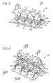
- all the movable contacts 11 a , 11 b , 11 c , 11 d are positionable.
- the multipole switch 30 is also a four-pole switch.
- the movable contacts 31 a , 31 b , 31 c , 31 d are fixed on a switching rod 33 while the fixed contacts 32 a , 32 b , 32 c , 32 d are fixed on a plate support 34.
- the switching rod 33 is, as before, rotatable around of its axis 35.
- each movable contact 31 a , 31 b , 31 c , 31 d and each corresponding fixed contact 32 a , 32 b , 32 c , 32 d is not identical from one pole to the other of the four-pole switch 30.
- the end poles made up of the two contact pairs 31 a , 32 a and 31 d , 32 d located at the ends of the switch 30 have a smaller difference than the two middle poles made up of the two pairs of contacts 31 b , 32 b and 31 c , 32 c located in the center of switch 30.
- the positionable contacts are the fixed contacts 32 a , 32 b , 32 c , 32 d of the switch 30, that is to say the mounted contacts on the support plate 34.
- the movable contacts 31 a , 31 b , 31 c , 31 d of the switch 30 are all positioned in an identical manner on the switching bar 33.
- the movable contact 31 b extends inside a housing 36 b formed on the switching rod 33. It is held in abutment against a wall 37 b of the housing 36 b by a thrust spring 38 b .
- Said movable contact 31b has substantially a bar shape having one end 39 b projecting from the housing 36 b.
- This end 39 b is adapted to establish electrical contact itself with the corresponding fixed contact 32 b.
- this movable contact 31 b has a notch 40 b adapted to cooperate with a lug 41 b of the wall 37 b of the housing 36 b .
- the fixed contacts 32 a , 32 b , 32 c , 32 d can occupy two distinct positions on the contact support 34.
- the fixed contacts 32 a , 32 b , 32 c , 32 d respectively comprise a fixing lug 42 a , 42 b , 42 c , 42 d extending a projecting portion 43 a , 43 b , 43 c , 43 d on the support plate 34, this projecting portion being adapted to come into actual contact with the corresponding movable contact 31 a , 31 b , 31 c , 31 d .
- the bracket 42 b comprises positioning means adapted to cooperate with complementary positioning means integral with the support plate 34.
- the fixing lug 42 b comprises two pairs of notches, 44 b , 45 b , offset along a longitudinal axis of the fixing lug 42 b .
- the fixing lug 42 b is slidably mounted between two rails 47 b each carrying a lug 46 b adapted to be housed in one or the other of the notches 44 b , 45 b of the lug fixing 42 b .
- Each fixed contact 32 a , 32 b , 32 c , 32 d can thus occupy two distinct positions on the contact support 34 so that the distance separating each fixed contact from the corresponding movable contact can be adjusted.
- Each fixed contact 32 a, 32 b, 32 c, 32 d is an associated flexible conductive member 48 a, 48b, 48 c, 48 d.
- Each element 48 a , 48 b , 48 c , 48 d has one end connected to an electrical connection integral with the support plate 34 and another end connected to the fixing lug 42 a , 42 b , 42 c , 42 d , of each fixed contact 32 a , 32 b , 32 c , 32 d , positionable.
- all the fixed contacts 32 a , 32 b , 32 c , 32 d are positionable.
Landscapes
- Push-Button Switches (AREA)
- Breakers (AREA)
Applications Claiming Priority (2)
| Application Number | Priority Date | Filing Date | Title |
|---|---|---|---|
| FR0001796A FR2805078B1 (fr) | 2000-02-14 | 2000-02-14 | Interrupteur multipolaire |
| FR0001796 | 2000-02-14 |
Publications (1)
| Publication Number | Publication Date |
|---|---|
| EP1126486A1 true EP1126486A1 (de) | 2001-08-22 |
Family
ID=8846968
Family Applications (1)
| Application Number | Title | Priority Date | Filing Date |
|---|---|---|---|
| EP01400347A Withdrawn EP1126486A1 (de) | 2000-02-14 | 2001-02-09 | Mehrpoliger Schalter |
Country Status (3)
| Country | Link |
|---|---|
| EP (1) | EP1126486A1 (de) |
| FR (1) | FR2805078B1 (de) |
| PL (1) | PL198444B1 (de) |
Cited By (4)
| Publication number | Priority date | Publication date | Assignee | Title |
|---|---|---|---|---|
| EP2743947A1 (de) * | 2012-12-14 | 2014-06-18 | Schneider Electric Industries SAS | Kontaktarme tragende Schaltwelle in einem Schaltgerät, und damit versehenes Schaltgerät, insbesondere ein Abzweigschalter |
| WO2018006770A1 (zh) * | 2016-07-06 | 2018-01-11 | 上海电科电器科技有限公司 | 断路器的导电回路 |
| WO2018006768A1 (zh) * | 2016-07-06 | 2018-01-11 | 上海电科电器科技有限公司 | 断路器的导电回路 |
| CN110428985A (zh) * | 2019-08-20 | 2019-11-08 | 国网福建省电力有限公司检修分公司 | 易更换式gw16/17型隔离开关动触片 |
Citations (2)
| Publication number | Priority date | Publication date | Assignee | Title |
|---|---|---|---|---|
| GB671999A (en) * | 1950-11-04 | 1952-05-14 | Wilfrid Brooke | Improvements in three phase electric switches or contactors |
| EP0639845A1 (de) * | 1993-08-17 | 1995-02-22 | Schneider Electric Sa | Vierpoliger Differentialschutzschalter |
-
2000
- 2000-02-14 FR FR0001796A patent/FR2805078B1/fr not_active Expired - Fee Related
-
2001
- 2001-02-09 EP EP01400347A patent/EP1126486A1/de not_active Withdrawn
- 2001-02-14 PL PL345841A patent/PL198444B1/pl not_active IP Right Cessation
Patent Citations (2)
| Publication number | Priority date | Publication date | Assignee | Title |
|---|---|---|---|---|
| GB671999A (en) * | 1950-11-04 | 1952-05-14 | Wilfrid Brooke | Improvements in three phase electric switches or contactors |
| EP0639845A1 (de) * | 1993-08-17 | 1995-02-22 | Schneider Electric Sa | Vierpoliger Differentialschutzschalter |
Cited By (4)
| Publication number | Priority date | Publication date | Assignee | Title |
|---|---|---|---|---|
| EP2743947A1 (de) * | 2012-12-14 | 2014-06-18 | Schneider Electric Industries SAS | Kontaktarme tragende Schaltwelle in einem Schaltgerät, und damit versehenes Schaltgerät, insbesondere ein Abzweigschalter |
| WO2018006770A1 (zh) * | 2016-07-06 | 2018-01-11 | 上海电科电器科技有限公司 | 断路器的导电回路 |
| WO2018006768A1 (zh) * | 2016-07-06 | 2018-01-11 | 上海电科电器科技有限公司 | 断路器的导电回路 |
| CN110428985A (zh) * | 2019-08-20 | 2019-11-08 | 国网福建省电力有限公司检修分公司 | 易更换式gw16/17型隔离开关动触片 |
Also Published As
| Publication number | Publication date |
|---|---|
| FR2805078B1 (fr) | 2004-09-17 |
| PL345841A1 (en) | 2001-08-27 |
| PL198444B1 (pl) | 2008-06-30 |
| FR2805078A1 (fr) | 2001-08-17 |
Similar Documents
| Publication | Publication Date | Title |
|---|---|---|
| FR2484344A1 (fr) | Unite d'entrainement electrique, notamment pour essuie-glace d'un vehicule automobile | |
| FR2870492A1 (fr) | Lampe d'eclairage interieure pour vehicule | |
| WO2010043604A1 (fr) | Appareil de commutation electrique muni de deux interrupteurs, tels qu'un sectionneur de barre et un sectionneur de terre et comprenant des moyens d'entrainement communs aux contacts mobiles des interrupteurs | |
| EP0863523B1 (de) | Multipolare elektrische Schalter | |
| EP2456021B1 (de) | Stromsteckdose mit seitlichen verschiebbaren Balken | |
| EP0693763A1 (de) | Mittelspannung elektrischer Schalter | |
| EP1126486A1 (de) | Mehrpoliger Schalter | |
| WO2016012699A1 (fr) | Ensemble de finition pour interrupteur electrique et interrupteur electrique avec un tel ensemble de finition | |
| EP0554171A1 (de) | Bürstenhalter für einen elektrischen Motor mit drehbarem Kollektor | |
| BE1004594A3 (fr) | Dispositif de condamnation mecanique et electrique pour contacteurs. | |
| EP4078641B1 (de) | Mechanismus für einen elektrischen schalter, elektrische baugruppe und elektrischer schalter dafür | |
| EP0891627B1 (de) | Modulare elektrische schalteranordung | |
| EP0639845B1 (de) | Vierpoliger Differentialschutzschalter | |
| EP1278224A1 (de) | Elektrische Verbindungsvorrichtung für zwei nebeneinander auf einer Schiene montierte elecktrische Geräte | |
| EP3840154A1 (de) | Wasserdichtes elektrogerät | |
| FR2576141A1 (fr) | Disjoncteur basse tension, avec verrou de maintien agence dans une chambre separee | |
| EP0921547A1 (de) | Elektrischer Schalter | |
| FR2778789A1 (fr) | Appareil de coupure electrique pour installation electrique a basse tension alternative | |
| EP0827162A1 (de) | Elektromagnet mit eingetauchtem Kern für zum Beispiel einen ferngesteuerten Schalter | |
| FR2726401A1 (fr) | Dispositif de raccordement electrique pour un accessoire amovible de vehicule automobile | |
| WO2007031681A1 (fr) | Contacteur de demarreur de moteur thermique comportant des moyens perfectionnes de raccordement electrique de son bobinage | |
| EP2442337B1 (de) | Schlüsselkontaktvorrichtung | |
| EP0818795A1 (de) | Schalter mit zwei beweglichen Kontakten wie Umschalter oder Schalter für Rolladen | |
| FR2727786A1 (fr) | Interrupteur a bascule a boitier modulaire | |
| FR3001082A3 (fr) | Contacteur electromagnetique |
Legal Events
| Date | Code | Title | Description |
|---|---|---|---|
| PUAI | Public reference made under article 153(3) epc to a published international application that has entered the european phase |
Free format text: ORIGINAL CODE: 0009012 |
|
| AK | Designated contracting states |
Kind code of ref document: A1 Designated state(s): AT BE CH CY DE DK ES FI FR GB GR IE IT LI LU MC NL PT SE TR |
|
| AX | Request for extension of the european patent |
Free format text: AL;LT;LV;MK;RO;SI |
|
| 17P | Request for examination filed |
Effective date: 20011026 |
|
| AKX | Designation fees paid |
Free format text: AT BE CH CY DE DK ES FI FR GB GR IE IT LI LU MC NL PT SE TR |
|
| 17Q | First examination report despatched |
Effective date: 20080924 |
|
| GRAJ | Information related to disapproval of communication of intention to grant by the applicant or resumption of examination proceedings by the epo deleted |
Free format text: ORIGINAL CODE: EPIDOSDIGR1 |
|
| GRAP | Despatch of communication of intention to grant a patent |
Free format text: ORIGINAL CODE: EPIDOSNIGR1 |
|
| GRAP | Despatch of communication of intention to grant a patent |
Free format text: ORIGINAL CODE: EPIDOSNIGR1 |
|
| STAA | Information on the status of an ep patent application or granted ep patent |
Free format text: STATUS: THE APPLICATION IS DEEMED TO BE WITHDRAWN |
|
| 18D | Application deemed to be withdrawn |
Effective date: 20091208 |