EP1126492B1 - Disjoncteur avec déclenchement instantané fourni par le conducteur principal passant par le circuit magnétique d'un circuit électronique de déclenchement - Google Patents
Disjoncteur avec déclenchement instantané fourni par le conducteur principal passant par le circuit magnétique d'un circuit électronique de déclenchement Download PDFInfo
- Publication number
- EP1126492B1 EP1126492B1 EP01103832A EP01103832A EP1126492B1 EP 1126492 B1 EP1126492 B1 EP 1126492B1 EP 01103832 A EP01103832 A EP 01103832A EP 01103832 A EP01103832 A EP 01103832A EP 1126492 B1 EP1126492 B1 EP 1126492B1
- Authority
- EP
- European Patent Office
- Prior art keywords
- circuit
- trip
- circuit breaker
- magnetic
- conductor
- Prior art date
- Legal status (The legal status is an assumption and is not a legal conclusion. Google has not performed a legal analysis and makes no representation as to the accuracy of the status listed.)
- Expired - Lifetime
Links
- 239000004020 conductor Substances 0.000 title claims description 26
- 230000007246 mechanism Effects 0.000 claims description 21
- 230000004907 flux Effects 0.000 claims description 14
- 230000004044 response Effects 0.000 claims description 6
- 210000003127 knee Anatomy 0.000 description 9
- 230000006835 compression Effects 0.000 description 2
- 238000007906 compression Methods 0.000 description 2
- 230000008878 coupling Effects 0.000 description 2
- 238000010168 coupling process Methods 0.000 description 2
- 238000005859 coupling reaction Methods 0.000 description 2
- 238000010438 heat treatment Methods 0.000 description 2
- 230000014759 maintenance of location Effects 0.000 description 2
- 230000013011 mating Effects 0.000 description 2
- 239000002184 metal Substances 0.000 description 2
- 230000002085 persistent effect Effects 0.000 description 2
- 230000000881 depressing effect Effects 0.000 description 1
- 230000000694 effects Effects 0.000 description 1
- 230000036039 immunity Effects 0.000 description 1
- 230000004048 modification Effects 0.000 description 1
- 238000012986 modification Methods 0.000 description 1
- 230000002035 prolonged effect Effects 0.000 description 1
- 230000001681 protective effect Effects 0.000 description 1
- 239000011347 resin Substances 0.000 description 1
- 229920005989 resin Polymers 0.000 description 1
- 230000035939 shock Effects 0.000 description 1
- 230000001960 triggered effect Effects 0.000 description 1
- 238000003466 welding Methods 0.000 description 1
Images


Classifications
-
- H—ELECTRICITY
- H01—ELECTRIC ELEMENTS
- H01H—ELECTRIC SWITCHES; RELAYS; SELECTORS; EMERGENCY PROTECTIVE DEVICES
- H01H83/00—Protective switches, e.g. circuit-breaking switches, or protective relays operated by abnormal electrical conditions otherwise than solely by excess current
- H01H83/20—Protective switches, e.g. circuit-breaking switches, or protective relays operated by abnormal electrical conditions otherwise than solely by excess current operated by excess current as well as by some other abnormal electrical condition
- H01H2083/201—Protective switches, e.g. circuit-breaking switches, or protective relays operated by abnormal electrical conditions otherwise than solely by excess current operated by excess current as well as by some other abnormal electrical condition the other abnormal electrical condition being an arc fault
Definitions
- This invention relates to circuit breakers of the type having a trip motor energized by a trip circuit responsive to selected fault conditions producing overcurrents smaller in magnitude than short circuit currents.
- it relates to a circuit breaker that couples the magnetic flux generated by short circuit currents into the magnetic circuit of the trip motor to trip the circuit breaker open independently of energization of the trip motor coil by the trip circuit.
- Such an arrangement is particularly advantageous in providing an instantaneous trip function for subminiature circuit breakers, but can also be applied to larger circuit breakers.
- subminiature circuit breakers are used in aircraft electrical systems where they not only provide overcurrent protection but also serve as switches for turning equipment on and off. As such, they are subjected to heavy use and therefore must be capable of performing reliably over many operating cycles. They also must be small to accommodate the high density layout of circuit breaker panels which make circuit breakers for numerous circuits accessible to a user. Subminiature circuit breakers can be used in an environment where they are subject to vibration. The circuit breaker must trip consistently within tolerance yet not be tripped out by vibration or shock loading.
- subminiature circuit breakers have only provided protection against persistent overcurrents implemented by a latch triggered by a bimetal responsive to I 2 R heating resulting from the overcurrent.
- Some aircraft systems have also provided ground fault protection, but through the use of additional devices, namely current transformers which in some cases are remotely located from the protective relay.
- additional protection and most importantly arc fault protection.
- arc faults which are typically high impedance faults and can be intermittent. Nevertheless, such arc faults can result in a fire.
- Opening of the contacts is also caused by a ground fault which excites coil 127.
- the contacts are latched in the open condition following a fault by the attraction of permanent magnet 113.
- the present invention is directed to a circuit breaker which can be miniaturized yet provides multiple protection functions.
- the circuit breaker has a main current conductor connected in series with the separable contacts and routed to induce magnetic flux in a trip motor which can be separately energized by an electronic trip circuit to actuate the latch member of a latchable operating mechanism to trip the separable contacts of the circuit breaker open.
- the circuit breaker comprises a housing, separable contacts mounted in the housing, a latchable operating mechanism including a latch member which when actuated unlatches to open the separable contacts, and a trip motor which actuates the latch member when energized.
- the circuit breaker further has an overcurrent assembly which includes a main current conductor connected in series with the separable contacts and routed to induce magnetic flux in the magnetic circuit of the trip motor to actuate the latch member in response to an overcurrent through the main current conductor of at least a predetermined magnitude.
- the circuit breaker includes a trip circuit energizing the trip motor in response to predetermined current conditions below the overcurrent of predetermined magnitude.
- these predetermined current conditions can be for instance an arc fault.
- the trip motor includes a coil and a magnetic circuit with the main current conductor being routed at least partially through this magnetic circuit so that magnetic flux generated by current in the main current conductor is coupled into the magnetic circuit thereby actuating the latch member.
- the main conductor is a flexible conductor and the trip motor further includes a bracket which extends the magnetic circuit of the trip motor at least partially around the flexible conductor.
- a frame which supports the latchable operating mechanism cooperates with the bracket to guide the flexible conductor through the magnetic circuit of the trip motor.
- the bracket is magnetically permeable to enhance the magnetic coupling of the flux generated in the flexible shunt into the magnetic circuit of the trip motor.
- the latch member of the latchable operating mechanism forms the armature of the trip motor which is attracted by flux generated in the magnetic circuit either by energization of the trip coil or a current of at least the predetermined magnitude in the main current conductor.
- circuit breakers can be used in aircraft ac systems which are typically 400 Hz but can also be used in dc systems. It will also become evident that the invention is applicable to other circuit breakers including those used in ac systems operating at other frequencies, and to larger circuit breakers.
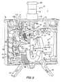
- the circuit breaker 1 has a housing 3 formed by first and second sections 3a and 3b molded of an insulative resin which are joined along a mating plane 5 to form an enclosure 7 from confronting cavities 7a and 7b.
- the housing 3 of the exemplary circuit breaker has a metallic top wall 9 although alternatively this top wall can be part of the molded sections 3a and 3b.
- the functional components of the circuit breaker 1 include a separable contact assembly 11, a toggle mechanism 13, a handle assembly 15, a latch assembly 17, and an overcurrent assembly 19.
- the toggle mechanism 13 and latch assembly 17 together form a latchable operating mechanism 18.
- a sheet metal frame 21 which as will be seen supports many of these functional components, is mounted in the cavity 7a in the molded section 3a by mounting holes 23 which engage molded pins in the housing section 3a as will be seen.
- the circuit breaker 1 also includes a line terminal 25 and load terminal 27 supported in the bottom of the molded housing and having cantilevered sections extending outside of the housing for connection to line and load conductors, respectively (not shown).
- the separable contact assembly 11 includes a fixed contact 29 fixed to the line terminal 25 and a moveable contact 31 carried by a contact arm 33.
- the fixed contact 29 and moveable contact 31 together form separable contacts 35.
- the contact arm 33 is pivotally mounted on a molded pin 37 which extends through one of the mounting holes 23 in the lower portion of the frame 21.
- a nut 39 retains the contact arm on the molded pin 37.
- a helical compression spring 40 forms a main spring which biases the contact arm counterclockwise as viewed in Figures 5-7 to open the separable contacts 35.
- the contact arm 33 is pivoted between open and closed positions of the separable contacts 35 by the toggle mechanism 13.
- This toggle mechanism 13 includes a bifurcated first toggle link 41 pivotally connected at a first or lower end 43 to the contact arm 33 by a pin 45.
- a bifurcated second toggle link 47 is pivotally connected at a first end 49 by a pin 51 to a latch lever 53 which in turn is pivotally mounted by a molded pin 55 which extends through one of the mounting holes 23 in the frame 21 and into a hole 57 in a flange 59 on the frame 21.
- Second ends 61 and 63 of the first toggle link 41 and second toggle link 47, respectively, are pivotally connected by a knee pin 65.
- the toggle mechanism 13 further includes a drive link 67 which couples the toggle mechanism 13 to the handle assembly 15.
- the handle assembly 15 includes a handle member 69 having a stem 69s which is pivotally connected to the drive link 67 of the toggle mechanism 13 by a pin 71.
- the handle member 69 is supported for reciprocal linear movement by a bezel 73 seated in the end in the top wall 9 and an indicator sleeve 75.
- the handle member 69 is captured by a handle retention pin 77 extending transversely through the bezel 73 and a slot 79 in the handle stem 69s.
- a helical compression handle spring 81 on the handle stem 69s bears against a washer 83 which seats on the handle retention pin 77.
- the latch assembly 17 includes in addition to the latch lever 53, a latch member 85.
- the latch member 85 has a finger 87 terminating in a hook 89 which forms a latch surface 91.
- the latch member 85 has a flat armature section 93 with an upward extension 95 from which the latch finger 87 extends at right angles.
- a flange 97 also extends at right angles to the upward extension parallel to the contact finger 87.
- a latch pin 99 extends through the flange 97 and latch finger 87 to pivotally mount the latch member between first flange 101 and a second confronting flange 103 on the frame 21 (see Figure 2).
- the toggle links 41 and 47 pivot in a first plane 105 while the latch member 85 pivots in a second plane 107 which is substantially perpendicular to the first plane 105.
- the contact arm 33, the latch lever 53 and the handle member 69 also move in the first plane.
- the first plane 105 is substantially parallel to the mating plane 5 of the molded sections 3a and 3b of the housing.
- the latch surface 91 on the latch member 85 engages the free end 53f on the latch lever 53 which is guided in a slot 106 in the flange 103 on the frame 21 (see Figures 2 and 3).
- a latch lever spring 108 biases the latch lever 53 toward the latched position at the lower end of the slot 106.
- the overcurrent assembly 19 includes a helical bimetal 109 which is fixed at one end to the load terminal 27.
- the free end 109f of the helical bimetal is connected by a main conductor in the form of a flexible shunt 111 to the contact arm 33.
- the load current which passes through the separable contacts 35 also passes through the helical bimetal 109. This causes I 2 R heating of the helical bimetal 109 resulting in unwinding of the free end 109f.
- the overcurrent assembly 19 also includes a cantilevered ambient compensator bimetal 113.
- One end of this ambient compensator bimetal is fixed to the latch member at the armature section 93 such as by spot welding.
- This cantilevered ambient compensator bimetal 113 has an offset around the latch pin 99 (see Figure 3) and extends upward to terminate in a free end 113f which is adjacent to the free end 109f of the helical bimetal 109 (see Figure 4).
- a flat latch spring 115 is bent to form a clamp 117 (see Figure 10) at the lower end which secures the flat latch spring to the frame 21 as shown in Figures 3 and 4.
- the free end 115f of this latch spring has a set which causes it to bear against the bimetal to bias the latch member 85 with the latch finger 87 forward. Under normal operating conditions there is a small gap between the free end 109 of the helical bimetal and the free end 115f of the ambient compensator bimetal.
- the thermal trip can be calibrated by a calibration screw 118 which is threaded in the free end of one of the bimetals 109, 113 and projects towards the other.
- this calibration screw 118 is seated in the free end 113f of the ambient compensator bimetal 113 as best seen in Figure 4.
- the overcurrent assembly 19 further includes a trip motor or solenoid 119.
- this trip motor 119 includes a magnetically permeable motor core 121 which fits inside a coil sleeve 122 within the coil 123.
- This subassembly is housed in a magnetically permeable motor cup 127 which together with magnetically permeable core 121 form a magnetic circuit represented by the arrows 124 in figure 3.
- a pin holder 129 projects laterally outward through a slot in the motor cup and supports a connector 131 having pins 133 for the coil 121.
- the coil cup has a shoulder 135 which seats in an opening 137 in the frame 21 (see Figure 2) with the motor core 121 facing the armature section 93 of the latch member 85.
- the trip motor 119 is energized through the electrical pins 133 by an electronic trip circuit 139 provided on a printed circuit board 141 shown in Figure 1.
- This trip circuit 139 provides for instance arc fault protection.
- the overcurrent assembly 19 includes an arrangement for routing the main conductor formed by the flexible shunt 111 through the magnetic circuit 124 of trip motor 119 as shown in Figures 3, 5-7 and 10.
- the magnetic circuit is extended by a magnetically permeable bracket or pole piece 143 which at least partially surrounds the flexible shunt 111, so that magnetic flux generated by the current in the flexible shunt 111 flows through the bracket 143, the core 121 and magnetic cup 135, and the armature 93 of the latch member 85.
- the very high current circulating through the flexible shunt 111 generates a magnetic field which is coupled into the magnetic circuit 124 of the trip motor and attracts the latch member 85 to move the latch finger 87 to the unlatched position.
- the bracket 143 cooperates with a support finger 144 on the metal frame 21 (see Figure 2) to secure the flexible shunt in place.
- the magnetic coupling is such that very high currents of at least a predetermined magnitude, such as those associated with short circuits, are sufficient to actuate the latch member 85 without energization of the coil 123 by the trip circuit 139.
- the circuit breaker 1 operates in the following manner.
- the handle member 69 is up with the indicator sleeve 75 visible to indicate the off condition.
- the latch lever 53 is latched by engagement of its free end 53a by the latch surface 91 on the latch member 85.
- the knee pin 65 of the toggle mechanism 13 is to the left of an imaginary line between the pins 45 and 51.
- the main spring 40 has rotated the contact arm 33 counterclockwise against the molded stop 145 so that the separable contacts 35 are open. This is the toggle open position of the toggle mechanism 13.
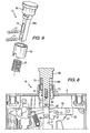
- the circuit breaker is turned on by depressing the handle member 69 which moves linearly downward to the position shown in Figure 6.
- the drive link 67 pushes the knee pin 65 downward which results in clockwise rotation of the contact arm against the main spring 40 through the first toggle link 41.
- the knee pin 65 translates counterclockwise until it passes through an imaginary line between the pins 45 and 51 at which point the main spring pressing up on the link 41 drives the knee pin 65 further counterclockwise until the toggle seats against the molded stop 147 in the toggle closed position shown in Figure 6.
- the circuit breaker 1 may be manually opened from the on position shown in Figure 6 to the off position shown in Figure 5 by raising the handle member 69. This translates the knee pin 65 counterclockwise through the drive link 67. Initially, a downward force is applied to the contact arm through the first toggle link 41, but when the knee pin passes through the center line between the pins 45 and 51, the toggle linkage breaks and the main spring 40 rotates the contact arm 33 counterclockwise until it seats against the molded stop 145 with the separable contacts 35 open. As the knee pin 65 translates clockwise the handle 69 rises to the off position shown in Figure 5.
- the circuit breaker 1 can be tripped to the open condition shown in Figure 7 under several conditions. If a persistent overcurrent occurs, the free end 109f of the helical bimetal 109 rotates counterclockwise as viewed in Figure 4 to engage the free end 113f of the ambient compensation bimetal and pushes it in the same direction to rotate the latch member 85 counterclockwise about the latch pin 99. This disengages the latch surface 91 to release the latch lever 53 which is driven clockwise about the molded pin 55 by the main spring which rotates the contact arm 33 counterclockwise to open the separable contacts 35 and through the toggle links 41 and 47. As this occurs, the handle spring 81 pulls the knee pin 65 through the center line between the pins 45 and 51.
- the circuit breaker 1 is reset from the trip condition shown in Figure 7 by the latch lever spring 108 which pulls the latch lever 53 counterclockwise with the help of the latch lever spring 108 until the free end 53f of the latch lever engages the cam surface 151 on the latch finger 87 to rotate the latch finger rearward.
- the latch spring 115 rotates the latch member 85 back clockwise to latch the latch lever 53.
- Ambient temperature conditions cause the free end 109f of the helical bimetal and the free end 113f of the ambient compensator bimetal to move in the same direction and thereby maintain the appropriate gap between the two bimetal free ends to eliminate the effects of changes in ambient temperature.
- the electronic trip circuit 139 monitors the current for characteristics of such faults and energizes the coil 123 of the trip motor 119.
- the magnetic flux generated by the energization of the coil 123 attracts the armature section 93 of the latch member toward the motor core 121 to slide the latch surface 91 off of the tip 53f of the latch lever 53 thereby tripping the circuit breaker 1 open in the manner discussed above for a thermal trip.
- the flexible shunt 111 In the event of a very high overcurrent of at least a predetermined magnitude such as could be associated with a short circuit, the flexible shunt 111 generates a magnetic field which is coupled into the bracket 143, the coil cup 135 and the trip motor core 121 to again attract the armature section 93 and rotate the latch member 85 to release the latch lever 53 and trip the circuit breaker in the manner described above.
- the circuit breaker 1 is a simple reliable mechanism which selectively provides multiple protection functions as well as serving as an off/on switch. As the toggle mechanism 13 and the latch 85 operate in perpendicular planes, the circuit breaker 1 has enhanced immunity to vibrations which typically are confined to a single plane. This arrangement also lends itself to automated assembly.
- the molded section 3a of the housing 3 is placed on a flat surface and the parts are all inserted from above.
- the frame 21, the toggle mechanism 13, the handle assembly 15, the latch assembly 17 and the bimetals 109,113 all fit into the cavity 7a in this section 3a of the housing 3.
- the trip motor 119 is seated in the opening 137 in the frame 21 and the printed circuit board 141 is connected to the electrical pins 133.
- the trip motor 119 and printed circuit board 141 which then project above the molded section 3a, extend into the enclosure portion 7a in the second molded section 3b which is placed over the section 3a and secured thereto by rivets (not shown).
Landscapes
- Breakers (AREA)
Claims (8)
- Disjoncteur comprenant :un boîtier (3) ;des contacts séparables (29, 31) montés dans ledit boîtier ;un mécanisme d'exploitation verrouillable (18) incluant un organe de verrouillage (85) qui lorsque actionné se déverrouille pour ouvrir lesdits contacts séparables ; etun ensemble de surintensité (19) comprenant :un circuit moteur de déclenchement (119) qui actionne ledit organe de verrouillage lorsque excité et ayant un circuit magnétique ;un conducteur de courant électrique principal (111) connecté en série avec lesdits contacts séparables et est fait passer pour induire un flux magnétique dans ledit circuit magnétique dudit circuit moteur de déclenchement qui actionne ledit organe de verrouillage en réponse à une surintensité à travers ledit conducteur de courant électrique principal d'au moins une amplitude prédéterminée ;un circuit de déclenchement (123) excitant ledit circuit moteur de déclenchement en réponse à des conditions de courant électrique prédéterminées en dessous de ladite surintensité d'une amplitude prédéterminée.
- Disjoncteur de la revendication 1 dans lequel ledit circuit de déclenchement excite ledit circuit moteur de déclenchement en réponse à des conditions prédéterminées telles qu'un défaut d'arc.
- Disjoncteur de la revendication 1 dans lequel ledit conducteur principal est fait passer au moins partiellement à travers ledit circuit magnétique pour coupler du flux magnétique généré par du courant électrique dans ledit conducteur principal dans ledit circuit magnétique.
- Disjoncteur de la revendication 3 dans lequel ledit conducteur principal est un conducteur flexible et ledit circuit moteur de déclenchement inclut en plus un support perméable magnétiquement qui entoure au moins partiellement ledit conducteur flexible et prolonge ledit circuit magnétique autour dudit conducteur flexible.
- Disjoncteur de la revendication 3 dans lequel ledit circuit moteur de déclenchement inclut un support perméable magnétiquement formant une pièce polaire concentrant du flux magnétique généré par un courant électrique dans ledit conducteur principal dans ledit circuit magnétique.
- Disjoncteur de la revendication 5 dans lequel ledit boîtier inclut un cadre supportant ledit mécanisme d'exploitation verrouillable et qui coopère avec ledit support pour guider ledit conducteur principal au moins partiellement à travers ledit circuit magnétique.
- Disjoncteur de la revendication 6 dans lequel ledit organe de verrouillage est perméable magnétiquement et forme une armature dudit circuit moteur de déclenchement qui est attiré par un flux dans ledit circuit magnétique pour déverrouiller le mécanisme d'exploitation verrouillable et ouvrir lesdits contacts séparables.
- Disjoncteur de la revendication 3 dans lequel ledit circuit moteur de déclenchement inclut en plus une bobine, et ledit organe de verrouillage est perméable magnétiquement et forme une armature dudit circuit moteur de déclenchement qui est attiré par du flux magnétique dans ledit circuit magnétique généré soit par excitation de ladite bobine de déclenchement par ledit circuit de déclenchement ou par du flux magnétique généré par ledit courant électrique d'au moins ladite amplitude prédéterminée dans ledit conducteur principal.
Applications Claiming Priority (2)
| Application Number | Priority Date | Filing Date | Title |
|---|---|---|---|
| US09/506,871 US6307453B1 (en) | 2000-02-15 | 2000-02-15 | Circuit breaker with instantaneous trip provided by main conductor routed through magnetic circuit of electronic trip motor |
| US506871 | 2000-02-15 |
Publications (3)
| Publication Number | Publication Date |
|---|---|
| EP1126492A2 EP1126492A2 (fr) | 2001-08-22 |
| EP1126492A3 EP1126492A3 (fr) | 2003-06-04 |
| EP1126492B1 true EP1126492B1 (fr) | 2006-11-15 |
Family
ID=24016306
Family Applications (1)
| Application Number | Title | Priority Date | Filing Date |
|---|---|---|---|
| EP01103832A Expired - Lifetime EP1126492B1 (fr) | 2000-02-15 | 2001-02-15 | Disjoncteur avec déclenchement instantané fourni par le conducteur principal passant par le circuit magnétique d'un circuit électronique de déclenchement |
Country Status (4)
| Country | Link |
|---|---|
| US (1) | US6307453B1 (fr) |
| EP (1) | EP1126492B1 (fr) |
| CA (1) | CA2336754A1 (fr) |
| DE (1) | DE60124439T2 (fr) |
Families Citing this family (17)
| Publication number | Priority date | Publication date | Assignee | Title |
|---|---|---|---|---|
| US6522509B1 (en) * | 2000-07-21 | 2003-02-18 | Eaton Corporation | Arc fault detection in ac electric power systems |
| US6542056B2 (en) * | 2001-04-30 | 2003-04-01 | Eaton Corporation | Circuit breaker having a movable and illuminable arc fault indicator |
| GB2386255A (en) * | 2002-03-04 | 2003-09-10 | Masterplug Ltd | Leakage current breaker |
| US6639492B1 (en) * | 2003-01-15 | 2003-10-28 | Eaton Corporation | Indicator reset tool, and circuit breaker and method employing the same |
| US7038897B2 (en) * | 2003-02-12 | 2006-05-02 | Honeywell International Inc. | Arc fault detection system |
| US6864446B1 (en) | 2004-03-31 | 2005-03-08 | Eaton Corporation | Internal rolling seal design for circuit breakers |
| US7518475B2 (en) * | 2007-07-24 | 2009-04-14 | Eaton Corporation | Electrical switching apparatus, circuit interrupter and method of interrupting overcurrents of a power circuit |
| US7570146B2 (en) * | 2007-07-25 | 2009-08-04 | Eaton Corporation | Circuit breaker including ambient compensation bimetal holding and releasing arc fault indicator |
| US8159318B2 (en) * | 2008-09-22 | 2012-04-17 | Siemens Industry, Inc. | Electromagnet assembly directly driving latch of an electronic circuit breaker |
| GB0915379D0 (en) * | 2009-09-03 | 2009-10-07 | Deepstream Technologies Ltd | Miniature circuit breaker |
| US8531256B2 (en) | 2011-09-27 | 2013-09-10 | Eaton Corporation | Tool and calibration machine for calibrating a thermal trip apparatus of a circuit interrupter, and improved method |
| US9230765B2 (en) * | 2012-11-02 | 2016-01-05 | Rockwell Automation Technologies, Inc. | Modular overload relay assembly with mechanically isolated connector |
| US9064646B2 (en) * | 2013-01-29 | 2015-06-23 | Hamilton Sundstrand Corporation | Electrical system lock out switch |
| US9184013B2 (en) * | 2013-06-21 | 2015-11-10 | General Electric Company | Conductor guide member for a circuit breaker terminal assembly |
| US9728348B2 (en) * | 2015-12-21 | 2017-08-08 | Eaton Corporation | Electrical switching apparatus with electronic trip unit |
| WO2018217883A2 (fr) | 2017-05-23 | 2018-11-29 | Pass & Seymour, Inc. | Interrupteur de circuit de défaut d'arc |
| US10984974B2 (en) * | 2018-12-20 | 2021-04-20 | Schneider Electric USA, Inc. | Line side power, double break, switch neutral electronic circuit breaker |
Family Cites Families (5)
| Publication number | Priority date | Publication date | Assignee | Title |
|---|---|---|---|---|
| US3273089A (en) * | 1963-04-29 | 1966-09-13 | Heinemann Electric Co | Circuit breaker linkage auxiliary tripping arrangement |
| US4812799A (en) | 1987-04-02 | 1989-03-14 | Texas Instruments Incorporated | Miniature circuit breaker with improved longevity |
| US5224006A (en) | 1991-09-26 | 1993-06-29 | Westinghouse Electric Corp. | Electronic circuit breaker with protection against sputtering arc faults and ground faults |
| PT847070E (pt) | 1996-02-06 | 2002-11-29 | Rockwell Automation Ag | Disjuntor de proteccao contra sobreintensidade de corrente electrica tratando-se nomeadamente de um disjuntor de proteccao para motores |
| US5886860A (en) | 1997-08-25 | 1999-03-23 | Square D Company | Circuit breakers with PTC (Positive Temperature Coefficient resistivity |
-
2000
- 2000-02-15 US US09/506,871 patent/US6307453B1/en not_active Expired - Lifetime
-
2001
- 2001-02-14 CA CA002336754A patent/CA2336754A1/fr not_active Abandoned
- 2001-02-15 DE DE60124439T patent/DE60124439T2/de not_active Expired - Lifetime
- 2001-02-15 EP EP01103832A patent/EP1126492B1/fr not_active Expired - Lifetime
Also Published As
| Publication number | Publication date |
|---|---|
| DE60124439T2 (de) | 2007-09-20 |
| CA2336754A1 (fr) | 2001-08-15 |
| US6307453B1 (en) | 2001-10-23 |
| EP1126492A2 (fr) | 2001-08-22 |
| EP1126492A3 (fr) | 2003-06-04 |
| DE60124439D1 (de) | 2006-12-28 |
Similar Documents
| Publication | Publication Date | Title |
|---|---|---|
| EP1126490B1 (fr) | Disjoncteur avec verrouillage et système de genouillère qui fonctionnent sur des plans différents | |
| US6710688B2 (en) | Circuit breaker | |
| EP1126492B1 (fr) | Disjoncteur avec déclenchement instantané fourni par le conducteur principal passant par le circuit magnétique d'un circuit électronique de déclenchement | |
| US6522228B2 (en) | Circuit breaker including an arc fault trip actuator having an indicator latch and a trip latch | |
| US5552755A (en) | Circuit breaker with auxiliary switch actuated by cascaded actuating members | |
| US6542056B2 (en) | Circuit breaker having a movable and illuminable arc fault indicator | |
| CA2292470C (fr) | Mecanisme d'actionnement de multiples microcontacts | |
| CA2412523C (fr) | Disjoncteur d'interrupteur de courant de defaut d'arc/d'interrupteur de courant de defaut a la terre pourvu d'un mecanisme a securite integree | |
| AU777311B2 (en) | Circuit breaker with bypass conductor commutating current out of the bimetal during short circuit interruption and method of commutating current out of bimetal | |
| US5565828A (en) | Circuit breaker | |
| US6879228B2 (en) | Circuit breaker including magnetic trip mechanism | |
| CA2023765C (fr) | Disjoncteur a declenchement magnetique a basse intensite | |
| US6838961B2 (en) | Self-contained mechanism on a frame | |
| US6917267B2 (en) | Non-conductive barrier for separating a circuit breaker trip spring and cradle | |
| US6759931B1 (en) | Magnetic member, circuit breaker employing the same, and method of manufacturing the same | |
| US3073926A (en) | Circuit breaker | |
| US6850134B2 (en) | Circuit breaker operating mechanism with a metal cradle pivot |
Legal Events
| Date | Code | Title | Description |
|---|---|---|---|
| PUAI | Public reference made under article 153(3) epc to a published international application that has entered the european phase |
Free format text: ORIGINAL CODE: 0009012 |
|
| AK | Designated contracting states |
Kind code of ref document: A2 Designated state(s): AT BE CH CY DE DK ES FI FR GB GR IE IT LI LU MC NL PT SE TR |
|
| AX | Request for extension of the european patent |
Free format text: AL;LT;LV;MK;RO;SI |
|
| PUAL | Search report despatched |
Free format text: ORIGINAL CODE: 0009013 |
|
| AK | Designated contracting states |
Designated state(s): AT BE CH CY DE DK ES FI FR GB GR IE IT LI LU MC NL PT SE TR |
|
| AX | Request for extension of the european patent |
Extension state: AL LT LV MK RO SI |
|
| 17P | Request for examination filed |
Effective date: 20031127 |
|
| AKX | Designation fees paid |
Designated state(s): DE FR |
|
| RTI1 | Title (correction) |
Free format text: CIRCUIT BREAKER WITH INSTANTANEOUS TRIP PROVIDED BY MAIN CONDUCTOR ROUTED THROUGH MAGNETIC CIRCUIT OF ELECTRONIC TRIP MOTOR |
|
| GRAP | Despatch of communication of intention to grant a patent |
Free format text: ORIGINAL CODE: EPIDOSNIGR1 |
|
| GRAS | Grant fee paid |
Free format text: ORIGINAL CODE: EPIDOSNIGR3 |
|
| GRAA | (expected) grant |
Free format text: ORIGINAL CODE: 0009210 |
|
| AK | Designated contracting states |
Kind code of ref document: B1 Designated state(s): DE FR |
|
| REF | Corresponds to: |
Ref document number: 60124439 Country of ref document: DE Date of ref document: 20061228 Kind code of ref document: P |
|
| ET | Fr: translation filed | ||
| PLBE | No opposition filed within time limit |
Free format text: ORIGINAL CODE: 0009261 |
|
| STAA | Information on the status of an ep patent application or granted ep patent |
Free format text: STATUS: NO OPPOSITION FILED WITHIN TIME LIMIT |
|
| 26N | No opposition filed |
Effective date: 20070817 |
|
| REG | Reference to a national code |
Ref country code: FR Ref legal event code: PLFP Year of fee payment: 16 |
|
| REG | Reference to a national code |
Ref country code: FR Ref legal event code: PLFP Year of fee payment: 17 |
|
| REG | Reference to a national code |
Ref country code: FR Ref legal event code: PLFP Year of fee payment: 18 |
|
| REG | Reference to a national code |
Ref country code: DE Ref legal event code: R082 Ref document number: 60124439 Country of ref document: DE Ref country code: DE Ref legal event code: R081 Ref document number: 60124439 Country of ref document: DE Owner name: EATON INTELLIGENT POWER LIMITED, IE Free format text: FORMER OWNER: EATON CORP., CLEVELAND, OHIO, US |
|
| PGFP | Annual fee paid to national office [announced via postgrant information from national office to epo] |
Ref country code: DE Payment date: 20200121 Year of fee payment: 20 |
|
| PGFP | Annual fee paid to national office [announced via postgrant information from national office to epo] |
Ref country code: FR Payment date: 20200122 Year of fee payment: 20 |
|
| REG | Reference to a national code |
Ref country code: DE Ref legal event code: R071 Ref document number: 60124439 Country of ref document: DE |