EP1126495A2 - Illumination d'un dispositif d'installation électrique/électronique - Google Patents
Illumination d'un dispositif d'installation électrique/électronique Download PDFInfo
- Publication number
- EP1126495A2 EP1126495A2 EP01101755A EP01101755A EP1126495A2 EP 1126495 A2 EP1126495 A2 EP 1126495A2 EP 01101755 A EP01101755 A EP 01101755A EP 01101755 A EP01101755 A EP 01101755A EP 1126495 A2 EP1126495 A2 EP 1126495A2
- Authority
- EP
- European Patent Office
- Prior art keywords
- component
- light source
- electrical
- installation device
- lighting
- Prior art date
- Legal status (The legal status is an assumption and is not a legal conclusion. Google has not performed a legal analysis and makes no representation as to the accuracy of the status listed.)
- Granted
Links
Images

Classifications
-
- H—ELECTRICITY
- H01—ELECTRIC ELEMENTS
- H01R—ELECTRICALLY-CONDUCTIVE CONNECTIONS; STRUCTURAL ASSOCIATIONS OF A PLURALITY OF MUTUALLY-INSULATED ELECTRICAL CONNECTING ELEMENTS; COUPLING DEVICES; CURRENT COLLECTORS
- H01R13/00—Details of coupling devices of the kinds covered by groups H01R12/70 or H01R24/00 - H01R33/00
- H01R13/02—Contact members
- H01R13/03—Contact members characterised by the material, e.g. plating, or coating materials
- H01R13/035—Plated dielectric material
-
- H—ELECTRICITY
- H01—ELECTRIC ELEMENTS
- H01R—ELECTRICALLY-CONDUCTIVE CONNECTIONS; STRUCTURAL ASSOCIATIONS OF A PLURALITY OF MUTUALLY-INSULATED ELECTRICAL CONNECTING ELEMENTS; COUPLING DEVICES; CURRENT COLLECTORS
- H01R33/00—Coupling devices specially adapted for supporting apparatus and having one part acting as a holder providing support and electrical connection via a counterpart which is structurally associated with the apparatus, e.g. lamp holders; Separate parts thereof
- H01R33/05—Two-pole devices
- H01R33/06—Two-pole devices with two current-carrying pins, blades or analogous contacts, having their axes parallel to each other
- H01R33/09—Two-pole devices with two current-carrying pins, blades or analogous contacts, having their axes parallel to each other for baseless lamp bulb
-
- H—ELECTRICITY
- H01—ELECTRIC ELEMENTS
- H01R—ELECTRICALLY-CONDUCTIVE CONNECTIONS; STRUCTURAL ASSOCIATIONS OF A PLURALITY OF MUTUALLY-INSULATED ELECTRICAL CONNECTING ELEMENTS; COUPLING DEVICES; CURRENT COLLECTORS
- H01R4/00—Electrically-conductive connections between two or more conductive members in direct contact, i.e. touching one another; Means for effecting or maintaining such contact; Electrically-conductive connections having two or more spaced connecting locations for conductors and using contact members penetrating insulation
- H01R4/28—Clamped connections, spring connections
- H01R4/48—Clamped connections, spring connections utilising a spring, clip, or other resilient member
- H01R4/4809—Clamped connections, spring connections utilising a spring, clip, or other resilient member using a leaf spring to bias the conductor toward the busbar
- H01R4/48185—Clamped connections, spring connections utilising a spring, clip, or other resilient member using a leaf spring to bias the conductor toward the busbar adapted for axial insertion of a wire end
- H01R4/4819—Clamped connections, spring connections utilising a spring, clip, or other resilient member using a leaf spring to bias the conductor toward the busbar adapted for axial insertion of a wire end the spring shape allowing insertion of the conductor end when the spring is unbiased
- H01R4/4821—Single-blade spring
Definitions
- the invention relates to lighting of an electrical / electronic installation device according to the preamble of claim 1.
- the invention can be general in illuminated electrical and electronic installation devices in flush-mounted as well as surface-mounted applications, especially in switches, buttons, dimmers, Sockets, electronic switching devices in bus systems, devices for communication technology etc. can be used.
- EP 0 626 715 B1 describes a light source with a T-shaped plug-in base known for use in electrical installation devices.
- the one for use A special lamp, for example glow lamp, is suitable for attached to the back of the device.
- the main disadvantage of this and well-known installation equipment lighting is that to create the lighting of an installation device very many individual parts are required.
- the light source known from EP 0 626 715 B1 in addition to the lighting or lamp part and a series resistor four individual parts, such as two plastic injection parts (upper part and lower part) to form the Plug-in base and two stamped and bent parts as electrical contact parts.
- the four parts can only be manufactured using relatively expensive tools.
- the contact parts will be there partly processed in the insert process in plastic injection molds.
- the assembly of these relatively small and delicate individual parts is often not possible automate, so that a time-consuming and expensive manual final assembly of the installation device lighting must be done.
- the invention has for its object to illuminate an electrical / electronic Installation device of the type mentioned with a simplified structure specify.
- the advantages that can be achieved with the invention are, in particular, that the proposed Lighting consists of very few individual parts, very few manufacturing steps needed and due to the very few necessary assembly steps is easy to install. This reduces the investment costs (for example the costs for tools for manufacturing the individual parts) and the assembly costs. Are advantageous no assembly and soldering processes required.
- the light or lamp part is accessible from the front of the installation device, for example when replacing a defective light or lamp part is advantageous.
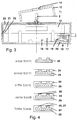
- the light source 1 shows a section through a light source (front view).
- the light source 1 consists of a light or lamp part 2, the plug insert in a base 3 is plugged in.
- the base 3 is made of a tubular upper part 4 and a Cross section square bottom part 5 is formed.
- the light source 1 is on or in a housing wall 10 attached to an electrical / electronic installation device.
- the housing wall 10 has a recess for receiving the square one Lower part 5 and a hole for carrying out and locking the tubular Top 4 on.
- connecting lines are in Grooves inserted in the recess of the housing wall 10. If contacting done via connecting tracks, such connecting tracks are as conductor tracks in the Housing wall 10 integrated (shown in dashed lines), which is preferably according to the MID technology explained in more detail below.
- the resilient contact tabs 7 of the base 3 are preferably a plastic injection molded part molded in one piece on the lower part 5 and are in direct contact with conductor tracks 8, which are integrated in the inner lateral surface of the tubular upper part 4. These one-piece molded conductor tracks 8 are in the area of the lighting or lamp part 2 designed as resilient contact parts and come into contact with connection contacts 9 of the inserted lighting or lamp part 2.
- FIG. 2 shows a section through a section of a light source (side view). It is the base 3 inserted in the housing wall 10 with the upper part 4 and Lower part 5 and a resilient contact tab 7 can be seen.
- Fig. 3 is a section through an electrical / electronic installation device with integrated Light source shown. It is an electrical / electronic installation device 11 with switch insert 12, rocker 13 with transparent window cutout 14 and upper housing part 15 and lower housing part 16 can be seen. An electrical connection line 17 engages through a hole in the lower housing part 16 in a resilient Terminal contact 18 (line terminal) of the switch insert 12. This terminal contact 18 is connected to a contact part 19 of the switching insert 12. In the switch insert 12 is at least one further (not shown) terminal contact for connection another connection line provided.
- the clamping contact 18 also contacts an integrated part in the lower housing part 16 Conductor path 20.
- This conductor path 20 extends over an electrical connection by means of contact spring 21 of the lower housing part 16 and mating contact 22 of the upper housing part 15 to a light source with an inserted light or lamp part 2 the top of the upper housing part 15.
- This conductor track 20 is in the housing wall 23 integrated.
- a further conductor track designed in the same way leads from the above-mentioned further terminal contact also to the light source.
- the design The light source of the installation device 11 can take place as in FIG. 1 and 2, the above-mentioned connecting tracks being the conductor tracks 20 correspond.
- the lockable configuration is preferably base 3 / upper part 4 / lower part 5 / Lugs 6 / contact lugs 7, however, by an integrated in the housing wall 23 Device replaced, hereinafter also referred to as an integrated light source.
- the housing wall 23 In the housing wall 23 is directly the insertion opening for receiving (inserting) and mechanical fixation of the light or lamp part 2 is formed while the connection contacts 9 of the light or lamp part in contact with those in the housing wall 23 integrated contact elements or conductor tracks 20 occur.
- Manufacture is preferably carried out using MID technology (Molded Interconnect Devices), specifically in two-component injection molding technology.
- MID technology Molded Interconnect Devices
- This special MID manufacturing process allows a high degree of design freedom, a Through-plating without additional measures and a high degree of flexibility of the layer structure, the efficiency of the manufacturing process being very high.
- a component 25 forming the conductor tracks 20 molded from a galvanizable plastic ("first shot”
- the component 25 is partially encased with a component 24 made of a non-galvanizable, electrically insulating plastic (“second shot”).
- Component 24 is used in particular to construct the housing wall 23 and thus to ensure a mechanically robust construction, for electrical insulation and to form the housing of the electrical / electronic installation device.
- component 25 is activated from the surface galvanizable plastic.
- the exposed ones are metallized Areas of component 25 made of the galvanizable plastic Application of a first metal layer 26 (basic metallization).
- a fifth Step is surface refinement by applying a second metal layer 27 with very good electrical conductivity to the base metallization Creation of the current-carrying conductor track 20 and creation of the electrical contact areas for the connecting contacts 9 of the light or lamp part 2.
- the proposed lighting offers a particularly advantageous possibility in that that the conductor tracks 8, 20 can be formed with resistance to to create a series resistor for the lighting or lamp part 2.
- the ohmic The resistance value of the conductor track is with regard to the applied nominal voltage aligned. This saves a separate series resistor, which and has cost advantages.
Landscapes
- Arrangement Of Elements, Cooling, Sealing, Or The Like Of Lighting Devices (AREA)
- Fastening Of Light Sources Or Lamp Holders (AREA)
- Push-Button Switches (AREA)
- Fittings On The Vehicle Exterior For Carrying Loads, And Devices For Holding Or Mounting Articles (AREA)
Applications Claiming Priority (2)
| Application Number | Priority Date | Filing Date | Title |
|---|---|---|---|
| DE10005030A DE10005030A1 (de) | 2000-02-04 | 2000-02-04 | Beleuchtung eines elektrischen/elektronischen Installationsgerätes |
| DE10005030 | 2000-02-04 |
Publications (3)
| Publication Number | Publication Date |
|---|---|
| EP1126495A2 true EP1126495A2 (fr) | 2001-08-22 |
| EP1126495A3 EP1126495A3 (fr) | 2003-01-08 |
| EP1126495B1 EP1126495B1 (fr) | 2003-11-05 |
Family
ID=7629895
Family Applications (1)
| Application Number | Title | Priority Date | Filing Date |
|---|---|---|---|
| EP01101755A Expired - Lifetime EP1126495B1 (fr) | 2000-02-04 | 2001-01-18 | Illumination d'un dispositif d'installation électrique/électronique |
Country Status (3)
| Country | Link |
|---|---|
| EP (1) | EP1126495B1 (fr) |
| AT (1) | ATE253771T1 (fr) |
| DE (2) | DE10005030A1 (fr) |
Cited By (1)
| Publication number | Priority date | Publication date | Assignee | Title |
|---|---|---|---|---|
| WO2004086822A1 (fr) * | 2003-03-25 | 2004-10-07 | sitronic Ges. für elektrotechnische Ausrüstung mbH & Co. KG | Module d'eclairage de vehicule automobile |
Family Cites Families (4)
| Publication number | Priority date | Publication date | Assignee | Title |
|---|---|---|---|---|
| DE1835478U (de) * | 1961-06-02 | 1961-07-27 | Broekelmann Jaeger & Busse K G | Fuer leuchtstoff-roehrenlampen mit zweistiftsockeln bestimmte fassung. |
| DE3410345A1 (de) * | 1984-03-21 | 1985-09-26 | Gebrüder Merten GmbH & Co KG, 5270 Gummersbach | Beleuchtetes elektrisches installationsgeraet |
| DE4317491A1 (de) * | 1993-05-26 | 1994-12-01 | Abb Patent Gmbh | Glimmlampe zum Einstecken |
| DE19700968A1 (de) * | 1997-01-14 | 1998-07-16 | Andreas Toeteberg | Leuchtenfertigmodul in Flachbauweise mit besonders rationeller und kompakter Ausgestaltung |
-
2000
- 2000-02-04 DE DE10005030A patent/DE10005030A1/de not_active Withdrawn
-
2001
- 2001-01-18 DE DE50100885T patent/DE50100885D1/de not_active Expired - Fee Related
- 2001-01-18 EP EP01101755A patent/EP1126495B1/fr not_active Expired - Lifetime
- 2001-01-18 AT AT01101755T patent/ATE253771T1/de not_active IP Right Cessation
Cited By (1)
| Publication number | Priority date | Publication date | Assignee | Title |
|---|---|---|---|---|
| WO2004086822A1 (fr) * | 2003-03-25 | 2004-10-07 | sitronic Ges. für elektrotechnische Ausrüstung mbH & Co. KG | Module d'eclairage de vehicule automobile |
Also Published As
| Publication number | Publication date |
|---|---|
| DE50100885D1 (de) | 2003-12-11 |
| DE10005030A1 (de) | 2001-08-09 |
| EP1126495B1 (fr) | 2003-11-05 |
| EP1126495A3 (fr) | 2003-01-08 |
| ATE253771T1 (de) | 2003-11-15 |
Similar Documents
| Publication | Publication Date | Title |
|---|---|---|
| EP0634888B1 (fr) | Unité enfichable, en particulier module de relais pour véhicules automobiles | |
| DE102019106980B3 (de) | Kontaktträger und Steckverbinder für eine geschirmte hybride Kontaktanordnung | |
| DE102008040460A1 (de) | In LED-Verbindungseinheit integrierte Verbindungsstückhalterung | |
| EP0848459A2 (fr) | Connecteur de ligne pour circuit imprimé | |
| DE102010031588A1 (de) | Draht/Platte-Verbinder | |
| DE202011108572U1 (de) | Adapter und Set aus Reihenklemme und Adapter | |
| EP1575131A1 (fr) | Connecteur électrique | |
| WO2003079499A1 (fr) | Connecteur pour reglettes de raccordement et son procede de production | |
| WO2007113030A1 (fr) | Module de raccordement pour raccorder une unité de commande ou équivalent à une unité d'entraînement | |
| DE2603151C3 (de) | Bauelement für Schalt- und/oder Trennleisten in Verteilern für Fernmeldeanlagen | |
| EP1126495B1 (fr) | Illumination d'un dispositif d'installation électrique/électronique | |
| DE10033571C2 (de) | Verwendung eines Bauteilträgers für elektronische Bauteile | |
| EP0871266B1 (fr) | Douille de lampe | |
| DE10061112A1 (de) | Steckverbindung für elektrische Bauelemente | |
| EP0626715B1 (fr) | Source lumineuse | |
| DE102004022791B4 (de) | Klemmkontakt für eine Leiterplatte und/oder Stanzgitter sowie Anordnung von Leiterplatten und/oder Stanzgitter | |
| DE10010356C1 (de) | Elektrisches Gerät sowie Baueinheit aus einem elektrischen Gerät und einer Lampenwanne | |
| DE29920404U1 (de) | Elektrischer Installationsschalter sowie Bauteilsystem und Glimmlampe für einen elektrischen Installationsschalter | |
| EP1122826B1 (fr) | Porte-fusible | |
| DE102006009582B4 (de) | Elektronisches Gerät eines Fahrzeuges, insbesondere ein Antennenverstärker oder ein TV-Tuner, mit einem Aufnahmeraum für einen Steckverbinder | |
| DE102006020045B4 (de) | Zwischenstecker und Verfahren zur Herstellung eines Zwischensteckers | |
| WO2007080069A1 (fr) | Appareil electrique | |
| DE29800780U1 (de) | Isolierstoffgehäuse für elektrische Geräte | |
| DE3934785A1 (de) | Lampenhalter- und klemmenplatte, insbesonderefuer haushaltsgeraete | |
| DE10037546A1 (de) | Elektrisches Installationsgerät mit integrierter Sicherung |
Legal Events
| Date | Code | Title | Description |
|---|---|---|---|
| PUAI | Public reference made under article 153(3) epc to a published international application that has entered the european phase |
Free format text: ORIGINAL CODE: 0009012 |
|
| AK | Designated contracting states |
Kind code of ref document: A2 Designated state(s): AT BE CH CY DE DK ES FI FR GB GR IE IT LI LU MC NL PT SE TR |
|
| AX | Request for extension of the european patent |
Free format text: AL;LT;LV;MK;RO;SI |
|
| RAP1 | Party data changed (applicant data changed or rights of an application transferred) |
Owner name: ABB PATENT GMBH |
|
| PUAL | Search report despatched |
Free format text: ORIGINAL CODE: 0009013 |
|
| AK | Designated contracting states |
Kind code of ref document: A3 Designated state(s): AT BE CH CY DE DK ES FI FR GB GR IE IT LI LU MC NL PT SE TR |
|
| AX | Request for extension of the european patent |
Free format text: AL;LT;LV;MK;RO;SI |
|
| 17P | Request for examination filed |
Effective date: 20030222 |
|
| GRAH | Despatch of communication of intention to grant a patent |
Free format text: ORIGINAL CODE: EPIDOS IGRA |
|
| RIN1 | Information on inventor provided before grant (corrected) |
Inventor name: SCHMIDT, KARSTEN Inventor name: NEUMANN, WOLFGANG Inventor name: ZAPP, ROBERT Inventor name: VOGT, FRIEDRICH |
|
| GRAS | Grant fee paid |
Free format text: ORIGINAL CODE: EPIDOSNIGR3 |
|
| GRAA | (expected) grant |
Free format text: ORIGINAL CODE: 0009210 |
|
| AKX | Designation fees paid |
Designated state(s): AT BE DE FR GB SE |
|
| AK | Designated contracting states |
Kind code of ref document: B1 Designated state(s): AT BE DE FR GB SE |
|
| REG | Reference to a national code |
Ref country code: GB Ref legal event code: FG4D Free format text: NOT ENGLISH |
|
| REF | Corresponds to: |
Ref document number: 50100885 Country of ref document: DE Date of ref document: 20031211 Kind code of ref document: P |
|
| REG | Reference to a national code |
Ref country code: IE Ref legal event code: FG4D Free format text: GERMAN |
|
| GBT | Gb: translation of ep patent filed (gb section 77(6)(a)/1977) |
Effective date: 20040104 |
|
| REG | Reference to a national code |
Ref country code: SE Ref legal event code: TRGR |
|
| ET | Fr: translation filed | ||
| REG | Reference to a national code |
Ref country code: IE Ref legal event code: FD4D |
|
| PLBE | No opposition filed within time limit |
Free format text: ORIGINAL CODE: 0009261 |
|
| STAA | Information on the status of an ep patent application or granted ep patent |
Free format text: STATUS: NO OPPOSITION FILED WITHIN TIME LIMIT |
|
| 26N | No opposition filed |
Effective date: 20040806 |
|
| PGFP | Annual fee paid to national office [announced via postgrant information from national office to epo] |
Ref country code: DE Payment date: 20050106 Year of fee payment: 5 |
|
| PGFP | Annual fee paid to national office [announced via postgrant information from national office to epo] |
Ref country code: GB Payment date: 20050110 Year of fee payment: 5 |
|
| PGFP | Annual fee paid to national office [announced via postgrant information from national office to epo] |
Ref country code: SE Payment date: 20050111 Year of fee payment: 5 Ref country code: FR Payment date: 20050111 Year of fee payment: 5 |
|
| PGFP | Annual fee paid to national office [announced via postgrant information from national office to epo] |
Ref country code: AT Payment date: 20050118 Year of fee payment: 5 |
|
| PGFP | Annual fee paid to national office [announced via postgrant information from national office to epo] |
Ref country code: BE Payment date: 20050223 Year of fee payment: 5 |
|
| PG25 | Lapsed in a contracting state [announced via postgrant information from national office to epo] |
Ref country code: GB Free format text: LAPSE BECAUSE OF NON-PAYMENT OF DUE FEES Effective date: 20060118 Ref country code: AT Free format text: LAPSE BECAUSE OF NON-PAYMENT OF DUE FEES Effective date: 20060118 |
|
| PG25 | Lapsed in a contracting state [announced via postgrant information from national office to epo] |
Ref country code: SE Free format text: LAPSE BECAUSE OF NON-PAYMENT OF DUE FEES Effective date: 20060119 |
|
| PG25 | Lapsed in a contracting state [announced via postgrant information from national office to epo] |
Ref country code: FR Free format text: LAPSE BECAUSE OF NON-PAYMENT OF DUE FEES Effective date: 20060131 Ref country code: BE Free format text: LAPSE BECAUSE OF NON-PAYMENT OF DUE FEES Effective date: 20060131 |
|
| PG25 | Lapsed in a contracting state [announced via postgrant information from national office to epo] |
Ref country code: DE Free format text: LAPSE BECAUSE OF NON-PAYMENT OF DUE FEES Effective date: 20060801 |
|
| EUG | Se: european patent has lapsed | ||
| GBPC | Gb: european patent ceased through non-payment of renewal fee |
Effective date: 20060118 |
|
| REG | Reference to a national code |
Ref country code: FR Ref legal event code: ST Effective date: 20060929 |
|
| BERE | Be: lapsed |
Owner name: *ABB PATENT G.M.B.H. Effective date: 20060131 |