EP1126535A2 - Dispositif de sécurité pour batterie polymère aux ions lithium - Google Patents
Dispositif de sécurité pour batterie polymère aux ions lithium Download PDFInfo
- Publication number
- EP1126535A2 EP1126535A2 EP01200070A EP01200070A EP1126535A2 EP 1126535 A2 EP1126535 A2 EP 1126535A2 EP 01200070 A EP01200070 A EP 01200070A EP 01200070 A EP01200070 A EP 01200070A EP 1126535 A2 EP1126535 A2 EP 1126535A2
- Authority
- EP
- European Patent Office
- Prior art keywords
- cell
- switch
- housing
- battery
- battery pack
- Prior art date
- Legal status (The legal status is an assumption and is not a legal conclusion. Google has not performed a legal analysis and makes no representation as to the accuracy of the status listed.)
- Withdrawn
Links
Images

Classifications
-
- H—ELECTRICITY
- H01—ELECTRIC ELEMENTS
- H01M—PROCESSES OR MEANS, e.g. BATTERIES, FOR THE DIRECT CONVERSION OF CHEMICAL ENERGY INTO ELECTRICAL ENERGY
- H01M50/00—Constructional details or processes of manufacture of the non-active parts of electrochemical cells other than fuel cells, e.g. hybrid cells
- H01M50/50—Current conducting connections for cells or batteries
- H01M50/572—Means for preventing undesired use or discharge
- H01M50/574—Devices or arrangements for the interruption of current
- H01M50/578—Devices or arrangements for the interruption of current in response to pressure
-
- H—ELECTRICITY
- H01—ELECTRIC ELEMENTS
- H01M—PROCESSES OR MEANS, e.g. BATTERIES, FOR THE DIRECT CONVERSION OF CHEMICAL ENERGY INTO ELECTRICAL ENERGY
- H01M10/00—Secondary cells; Manufacture thereof
- H01M10/42—Methods or arrangements for servicing or maintenance of secondary cells or secondary half-cells
- H01M10/425—Structural combination with electronic components, e.g. electronic circuits integrated to the outside of the casing
-
- H—ELECTRICITY
- H01—ELECTRIC ELEMENTS
- H01M—PROCESSES OR MEANS, e.g. BATTERIES, FOR THE DIRECT CONVERSION OF CHEMICAL ENERGY INTO ELECTRICAL ENERGY
- H01M10/00—Secondary cells; Manufacture thereof
- H01M10/42—Methods or arrangements for servicing or maintenance of secondary cells or secondary half-cells
- H01M10/48—Accumulators combined with arrangements for measuring, testing or indicating the condition of cells, e.g. the level or density of the electrolyte
-
- H—ELECTRICITY
- H01—ELECTRIC ELEMENTS
- H01M—PROCESSES OR MEANS, e.g. BATTERIES, FOR THE DIRECT CONVERSION OF CHEMICAL ENERGY INTO ELECTRICAL ENERGY
- H01M50/00—Constructional details or processes of manufacture of the non-active parts of electrochemical cells other than fuel cells, e.g. hybrid cells
- H01M50/50—Current conducting connections for cells or batteries
- H01M50/572—Means for preventing undesired use or discharge
- H01M50/574—Devices or arrangements for the interruption of current
-
- H—ELECTRICITY
- H01—ELECTRIC ELEMENTS
- H01M—PROCESSES OR MEANS, e.g. BATTERIES, FOR THE DIRECT CONVERSION OF CHEMICAL ENERGY INTO ELECTRICAL ENERGY
- H01M10/00—Secondary cells; Manufacture thereof
- H01M10/05—Accumulators with non-aqueous electrolyte
- H01M10/052—Li-accumulators
- H01M10/0525—Rocking-chair batteries, i.e. batteries with lithium insertion or intercalation in both electrodes; Lithium-ion batteries
-
- H—ELECTRICITY
- H01—ELECTRIC ELEMENTS
- H01M—PROCESSES OR MEANS, e.g. BATTERIES, FOR THE DIRECT CONVERSION OF CHEMICAL ENERGY INTO ELECTRICAL ENERGY
- H01M10/00—Secondary cells; Manufacture thereof
- H01M10/42—Methods or arrangements for servicing or maintenance of secondary cells or secondary half-cells
- H01M10/44—Methods for charging or discharging
-
- Y—GENERAL TAGGING OF NEW TECHNOLOGICAL DEVELOPMENTS; GENERAL TAGGING OF CROSS-SECTIONAL TECHNOLOGIES SPANNING OVER SEVERAL SECTIONS OF THE IPC; TECHNICAL SUBJECTS COVERED BY FORMER USPC CROSS-REFERENCE ART COLLECTIONS [XRACs] AND DIGESTS
- Y02—TECHNOLOGIES OR APPLICATIONS FOR MITIGATION OR ADAPTATION AGAINST CLIMATE CHANGE
- Y02E—REDUCTION OF GREENHOUSE GAS [GHG] EMISSIONS, RELATED TO ENERGY GENERATION, TRANSMISSION OR DISTRIBUTION
- Y02E60/00—Enabling technologies; Technologies with a potential or indirect contribution to GHG emissions mitigation
- Y02E60/10—Energy storage using batteries
Definitions
- the present invention relates generally to batteries, more particularly to a safety device for a thin lithium-ion battery.
- Improvements in micro-electronics have increased the demand for electrolytic cells in batteries that can be directly incorporated into electronic devices so as to produce a portable finished package, such as for example a cellular phone or a lap top computer.
- improvements in micro-electronics reduce the size of the electronic device, the space allotted to a power supply within such device has likewise decreased. It is therefore important to maximize the power per unit space that a battery cell can provide.
- a cell contained within a flexible laminate package provides more efficient use of the space available within a device, in that the cell and package can assume a variety of shapes allowing the battery design to accommodate the space restrictions within the device.
- a problem with cells contained within flexible packaging is that they are sensitive to temperature and over-voltage or over-current conditions.
- cells within flexible packages tend to "gas-up” or “swell-up” under extreme temperatures or under extreme over-voltage or over-current conditions.
- Excessive heat, current or voltage can cause the liquid electrolyte within the cell to decompose into a combustible gaseous by-product. Internal pressures created by this buildup of gas may cause the flexible packaging to swell and even rupture.
- the electrodes become resistive elements and energy provided thereto (for example by a battery charger) is converted to heat. If the electrode temperatures exceed the flash point of the hydrocarbon gases generated within the cell, the flexible packaging may rupture. While flexible packaging is less susceptible to a violent venting or catastrophic failure as compared to rigid metal or plastic containers, ruptures of the flexible packaging can damage electronic equipment in the vicinity of the cell.
- the present invention overcomes this and other problems and provides a lithium ion battery having a current interrupt safety feature to prevent catastrophic failure with flexible packaging.
- a battery comprised of a rigid, plastic housing defining a generally rectangular cavity.
- the housing has an intentionally flat surface and a plurality of openings extending from the cavity through the housing.
- a rechargeable electric cell having a flexible outer package is contained within the cavity of the housing.
- the cell is generally rectangular in shape and has a flat outer surface and two leads. The leads extend from the cell through select ones of the plurality of openings through the housing.
- the cell has a normal configuration when experiencing normal operating conditions and an abnormal configuration when experiencing abnormal operating conditions.
- a flat planar switch is disposed between the flat interior surface of the housing and the flat outer surface of the cell.
- the switch has at least one switch lead extending therefrom through another of the plurality of openings through the housing.
- the switch has a first electrical condition when the cell has a normal configuration and a second electrical condition when the cell has an abnormal configuration.
- a battery pack comprised of a rigid housing, and a rechargeable electric cell contained within the housing.
- the cell has a flexible outer packaging that maintains a normal configuration when experiencing normal operating conditions and an abnormal configuration when experiencing abnormal operating conditions.
- the cell has a negative lead and a positive lead that are electrically connected to external contacts on the housing. The contacts are adapted to engage contacts on a load or an electrical charging device.
- An electrical circuit within the housing is connected across the positive lead and the negative lead.
- the circuit includes a switch element disposed between an interior surface of the housing and an external surface of the cell. The switch element has a normally open switch position when the cell is in the normal configuration and a closed switch position when the cell is in the abnormal condition.
- the circuit also includes a breaking device having a first closed position connecting the positive lead to a respective one of the external contacts when the switch element is in the normally open switch position, and a second open position breaking the electrical connection between the positive lead and the respective one of the external contacts when the switch element is in the closed switch position.
- Another object of the present invention is to provide a rechargeable battery pack as described above that is comprised of a housing containing an electrical cell having a flexible outer package and a switch mechanism operable to sense abnormal operating conditions.
- Another object of the present invention is to provide a rechargeable battery pack as described above wherein the cell is contained within a flexible outer package and the switch mechanism is disposed within the housing between the cell and the housing.
- a still further object of the present invention is to provide a rechargeable battery pack as defined above including electrical circuitry to prevent the cell from experiencing abnormal operating conditions and to prevent damage to circuits and components external to the battery pack.
- FIG. 1 shows, in exploded view, a battery pack 10 illustrating a preferred embodiment of the present invention.
- battery pack 10 is comprised of a housing 20, a battery 70 and a switch 90.
- Housing 20 is comprised of a lower housing section 22 and an upper housing section 24. Housing sections 22, 24 together define an inner cavity 26 that is dimensioned to receive electrical cell 70.
- Lower housing section 22 is comprised of a generally planar bottom wall 28, side walls 32, 34 and end walls 36, 38. The upper ends of side walls 32, 34 and end walls 36, 38 are undercut to define a lip 42 and a ledge 44.
- a plurality of spaced apart recesses 46 are formed within ledges 44 of side walls 32, 34 and end walls 36, 38.
- four contact slots, designated 52a, 52b, 52c, and 52d are formed in side wall 32. Each contact slot 52a, 52b, 52c and 52d includes an opening 54, that extends through side wall 32 and communicates with cavity 26, and a contact mounting plate 56.
- Upper housing section 24 is generally rectangular in shape and is dimensioned to rest upon ledges 44 of side walls 32, 34 and end walls 36, 38, as best illustrated in FIG. 2.
- Upper housing section 24 includes a plurality of spaced apart tabs 62 that are dimensioned to be in registry with recesses 46 in lips 42 of side walls 32, 34 and end walls 36, 38.
- tabs 62 are generally wedge shaped and are operable to snap-lock into recesses 46 to secure upper housing section 24 to lower housing section 22.
- Battery 70 is generally comprised of a lithium ion cell (not shown) contained within a flexible package 72.
- the cell is generally comprised of flat electrodes (anode, separator and cathode) and a liquid electrolyte.
- the composition of the lithium ion cell in and of itself forms no part of the present invention.
- Packaging 72 is generally formed from a laminate comprised of one or more layers of metallic foil and/or one or more layers of a polymer material (not shown). The composition and make-up of the laminate in and of itself forms no part of the present invention.
- Packaging 72 is generally sealed by means of pressure and heat to form a seam 76 along one edge thereof.
- a pair of conductive leads 82, 84 extends from battery 70. As best seen in FIG.
- leads 82, 84 are formed to include a generally C-shaped portion.
- the C-shaped portion of leads 82, 84 are dimensioned to extend through opening 54 in side wall 32, and to snap-lock onto contact mounting plate 56. As best illustrated in FIG. 2, a portion of each lead 82, 84 is exposed at contact mounting slots 52a and 52d, respectively.
- planar switch 90 is a thin, flat, sheet-like device having leads 92 and 94 extending from one edge thereof. Like leads 82, 84 of battery 70, leads 92, 94 include a generally C-shaped portion dimensioned to extend through openings 54 in contact slots 52b and 52c and to snap onto contact mounting plates 56.
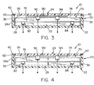
- switch 90 is a membrane switch having two switch conditions. Switch 90 is disposed between generally planar surface 74 of cell 70 and interior surface 24a of upper housing section 24, as best seen in FIGS. 3 and 4.
- Membrane switch 90 is selected to have a predetermined operating pressure related to the size and shape of battery 70.
- membrane switches are available in a variety of shapes and actuation pressures, and can essentially be formed to conform to any desired topology. In the context of the present invention, it is only important that the actuation force of the membrane switch be sized relative to the battery with which it is used.
- Switch 90 preferably has a first operating condition wherein switch 90 is in a normal, "open” position, and a second operating condition wherein switch 90 is in a “closed” position when the "actuation force" of the switch has been attained.
- battery 70 and switch 90 are disposed within cavity 26 of housing 20. Electrical leads 82, 84 of battery 70 extend through openings 54 of contact slots 52a and 52d, and leads 92, 94 of switch 90 extend through openings 54 of contact slots 52b and 52c. With cell 70 and switch 90 in position in cavity 26, upper housing section 24 is snap-locked onto lower housing section 22 to form battery pack 10, best seen in cross-section in FIGS. 3 and 4. Battery pack 10 thus provides an electrical battery 70 and a safety device 90 enclosed within a compact housing 20. Leads 82, 84 of battery 70, as well as leads 92, 94 of switch 90, are exposed on the outer surface of side wall 32 for operative engagement with opposing contacts of an electrical device, or opposing contacts in a battery charger.
- housing 20 is dimensioned to fit within an opening of an electronic device (not shown), or within an opening or slot within a battery charger (not shown).
- Leads 82, 84 of battery 70 are positioned to engage corresponding power leads of the electronic device or battery charger.
- Leads 92, 94 from switch 90 are positioned to engage corresponding leads from a circuit (not shown) within the electronic device or battery charger.
- the circuit is preferably adapted to break the electrical connection between battery pack 10 if switch 90 changes from its first condition to its second condition.
- the circuit may also provide an "indication" of the switch condition, such as for example, by conveying a signal to an audible, visual or other electrical device.
- battery 70 When in place in an electronic device or battery charger, battery 70 maintains a generally planar, "normal configuration", as illustrated in FIG. 3, under normal operating conditions.
- the liquid electrolyte in battery 70 may begin to decompose into some combustible gaseous by-product, thereby causing flexible packaging 72 to swell, as illustrated in FIG. 4.
- the swelling of package 72 compresses membrane switch 90 against upper housing section 24.
- membrane switch 90 switches from its first (open) condition to its a second (closed) condition, thereby providing an electrical signal to the external circuit to break the electrical connection between battery pack 10 and the electronic device or battery charger.
- the present invention thus provides a safety device (i.e., switch 90) within battery pack 10 to prevent catastrophic failure of battery 70, that may result from an over-voltage or over-current condition.
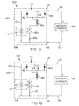
- Battery pack 100 is comprised of a housing 102, an electrical battery 110, a switch 120 and a circuit 140.
- Housing 102, battery 110 and switch 120 are preferably similar to those previously described with respect to battery pack 10.
- housing 102 would be a two-piece structure containing a battery 110 having flexible outer packaging as previously described.
- Switch 120 is a membrane switch of the type previously described, and is disposed between a surface of battery 110 and a surface of housing 102.
- Leads 104, 106 extend from battery 110 and include a portion that extends outside housing 102.
- battery pack 100 is shown connected to a battery charger 130 having leads 132, 134.
- Battery charger lead 132 is connected to battery pack lead 104 and a battery charger lead 134 connected to a battery pack 106.
- circuit 140 is contained within housing 102, and is adapted to prevent catastrophic failure of cell 110.
- Circuit 140 includes a resistive element 142 and a contact 144 that is controlled by a solenoid 146.
- Resistive element 142 is connected in series to switch 120 that is in turn connected in series to solenoid 146.
- a pair of diodes 152, 154 are connected in parallel across switch 144 and are together connected in series to solenoid 146.
- FIG. 5 shows battery pack 100 in a normal operating condition wherein cell 110 has a normal configuration, and membrane switch 120 is in an open position (i.e., its first, normal position).
- battery charger 130 is operable to charge battery 110 as lead 104 from battery pack 100 is connected to lead 132 of battery charger 130 and lead 106 of battery pack 100 is connected to lead 134 of battery charger 130.
- cell 110 will begin to swell (as described above) thereby causing membrane switch 120 to close and complete circuit 140 between lead 104 and 106.
- a conductive path is found through resistive element 142, membrane switch 120 and diode 154.
- FIGS. 5 and 6 thus illustrate how a simple circuit may be provided within battery pack 100 so as to prevent catastrophic failure of cell 110, and at the same time, prevent damage to external circuits and components, such as battery charger 130, by providing a resistive circuit path.
Landscapes
- Chemical & Material Sciences (AREA)
- Chemical Kinetics & Catalysis (AREA)
- Electrochemistry (AREA)
- General Chemical & Material Sciences (AREA)
- Engineering & Computer Science (AREA)
- Manufacturing & Machinery (AREA)
- Microelectronics & Electronic Packaging (AREA)
- Battery Mounting, Suspending (AREA)
- Connection Of Batteries Or Terminals (AREA)
- Secondary Cells (AREA)
- Sealing Battery Cases Or Jackets (AREA)
Applications Claiming Priority (2)
| Application Number | Priority Date | Filing Date | Title |
|---|---|---|---|
| US506912 | 1974-09-17 | ||
| US09/506,912 US6175213B1 (en) | 2000-02-18 | 2000-02-18 | Safety device for lithium-ion-polymer battery |
Publications (2)
| Publication Number | Publication Date |
|---|---|
| EP1126535A2 true EP1126535A2 (fr) | 2001-08-22 |
| EP1126535A3 EP1126535A3 (fr) | 2003-01-29 |
Family
ID=24016442
Family Applications (1)
| Application Number | Title | Priority Date | Filing Date |
|---|---|---|---|
| EP01200070A Withdrawn EP1126535A3 (fr) | 2000-02-18 | 2001-01-11 | Dispositif de sécurité pour batterie polymère aux ions lithium |
Country Status (5)
| Country | Link |
|---|---|
| US (1) | US6175213B1 (fr) |
| EP (1) | EP1126535A3 (fr) |
| JP (1) | JP2001229893A (fr) |
| KR (1) | KR20010081977A (fr) |
| TW (1) | TW513836B (fr) |
Cited By (5)
| Publication number | Priority date | Publication date | Assignee | Title |
|---|---|---|---|---|
| EP1878071A4 (fr) * | 2005-05-02 | 2009-11-25 | Lg Chemical Ltd | Bloc de batteries de moyenne ou grande taille ameliore pour securite accrue |
| WO2011120632A1 (fr) * | 2010-03-19 | 2011-10-06 | Li-Tec Battery Gmbh | Boîtier de batterie pour loger des éléments accumulateurs d'énergie électrochimiques |
| USD674747S1 (en) | 2010-11-16 | 2013-01-22 | Micro Power Electronics, Inc. | Battery pack |
| CN103779612A (zh) * | 2013-12-19 | 2014-05-07 | 宁波维科电池股份有限公司 | 一种软包装锂离子动力电池的制备方法 |
| EP3540906A1 (fr) * | 2018-03-15 | 2019-09-18 | Ascending Energy Inc. | Surveillance de l'état de santé et protection de sécurité pour modules de batterie au lithium-ion et applications |
Families Citing this family (20)
| Publication number | Priority date | Publication date | Assignee | Title |
|---|---|---|---|---|
| USD484850S1 (en) | 2002-11-22 | 2004-01-06 | Milwaukee Electric Tool Corporation | Battery |
| EP1473786B1 (fr) * | 2003-04-29 | 2016-08-10 | Sony Mobile Communications Inc. | Batterie pour un dispositif électronique |
| USD539221S1 (en) | 2004-05-21 | 2007-03-27 | Milwaukee Electric Tool Corporation | Battery |
| JP2006269345A (ja) * | 2005-03-25 | 2006-10-05 | Nec Lamilion Energy Ltd | 過電圧検出方法、装置及びバッテリパック |
| JPWO2007043392A1 (ja) * | 2005-10-03 | 2009-04-16 | Tdkラムダ株式会社 | 電池パック |
| USD558670S1 (en) | 2006-01-09 | 2008-01-01 | Milwaukee Electric Tool Corporation | Battery |
| US20070173090A1 (en) * | 2006-01-10 | 2007-07-26 | Johnson Todd W | Battery pack |
| JP5004769B2 (ja) * | 2006-11-21 | 2012-08-22 | 日立ビークルエナジー株式会社 | 二次電池モジュール |
| US20090047572A1 (en) * | 2007-08-16 | 2009-02-19 | Micropower Electronics, Inc. | Controlled pressure release for packaged batteries and associated systems and methods |
| US20090188105A1 (en) * | 2008-01-28 | 2009-07-30 | Ming-Chin Chien | Slim battery packaging method |
| DE102009058444A1 (de) * | 2009-12-16 | 2011-06-22 | Li-Tec Battery GmbH, 01917 | Batteriegehäuse zur Aufnahme von elektrochemischen Energiespeichereinrichtungen |
| DE102010026093A1 (de) * | 2010-07-05 | 2012-01-05 | Li-Tec Battery Gmbh | Galvanische Zelle |
| CN103441226B (zh) * | 2013-08-30 | 2015-09-30 | 苏州佳世达电通有限公司 | 组合式电池 |
| CN103715379B (zh) * | 2013-12-23 | 2016-03-09 | 苏州佳世达电通有限公司 | 一种电池及其包装方法 |
| JP6696426B2 (ja) * | 2014-08-19 | 2020-05-20 | 日本電気株式会社 | 電流遮断機能を有する電池およびその製造方法 |
| US10158149B2 (en) | 2014-11-20 | 2018-12-18 | Motorola Solutions, Inc. | Method and apparatus to detect and manage battery pack cell swell |
| US20170054304A1 (en) * | 2015-08-17 | 2017-02-23 | Mattel, Inc. | Mechanical Battery Ramp |
| CN109119704B (zh) * | 2018-08-28 | 2020-01-21 | 力源电池科技(深圳)有限公司 | 一种软包锂电池封装抽真空机器人 |
| CN115244759A (zh) | 2019-12-16 | 2022-10-25 | 戴森技术有限公司 | 具有内部膨胀消除和外部冷却特征的电池单元 |
| KR20220076835A (ko) * | 2020-12-01 | 2022-06-08 | 주식회사 엘지에너지솔루션 | 이차전지 및 이를 포함하는 디바이스 |
Family Cites Families (8)
| Publication number | Priority date | Publication date | Assignee | Title |
|---|---|---|---|---|
| FR1497093A (fr) * | 1965-10-24 | 1967-10-06 | Texas Instruments Inc | Batterie perfectionnée |
| US4275739A (en) * | 1979-01-26 | 1981-06-30 | The Johns Hopkins University | Charge control switch responsive to cell casing deflection |
| JPS569972A (en) * | 1979-07-05 | 1981-01-31 | Japan Storage Battery Co Ltd | Laminated battery of flat-type nickel cadmium battery and its charge control mechanism |
| JPS62190667A (ja) * | 1986-02-14 | 1987-08-20 | Matsushita Electric Ind Co Ltd | 密閉形鉛蓄電池 |
| US5656355A (en) * | 1992-03-12 | 1997-08-12 | Kimberly-Clark Corporation | Multilayer elastic metallized material |
| JP3573293B2 (ja) * | 1993-11-24 | 2004-10-06 | 日本電池株式会社 | 電池 |
| GB2305292B (en) * | 1995-09-18 | 1999-02-10 | Nokia Mobile Phones Ltd | Recharging electrical cells |
| US5800937A (en) * | 1997-05-02 | 1998-09-01 | Motorola, Inc. | Current interrupt device for secondary batteries |
-
2000
- 2000-02-18 US US09/506,912 patent/US6175213B1/en not_active Expired - Fee Related
- 2000-10-24 TW TW089122329A patent/TW513836B/zh active
- 2000-10-30 JP JP2000329737A patent/JP2001229893A/ja active Pending
- 2000-12-23 KR KR1020000081152A patent/KR20010081977A/ko not_active Abandoned
-
2001
- 2001-01-11 EP EP01200070A patent/EP1126535A3/fr not_active Withdrawn
Cited By (7)
| Publication number | Priority date | Publication date | Assignee | Title |
|---|---|---|---|---|
| EP1878071A4 (fr) * | 2005-05-02 | 2009-11-25 | Lg Chemical Ltd | Bloc de batteries de moyenne ou grande taille ameliore pour securite accrue |
| WO2011120632A1 (fr) * | 2010-03-19 | 2011-10-06 | Li-Tec Battery Gmbh | Boîtier de batterie pour loger des éléments accumulateurs d'énergie électrochimiques |
| CN102884653A (zh) * | 2010-03-19 | 2013-01-16 | 锂电池科技有限公司 | 容纳电化学储能电池的电池外壳 |
| USD674747S1 (en) | 2010-11-16 | 2013-01-22 | Micro Power Electronics, Inc. | Battery pack |
| CN103779612A (zh) * | 2013-12-19 | 2014-05-07 | 宁波维科电池股份有限公司 | 一种软包装锂离子动力电池的制备方法 |
| EP3540906A1 (fr) * | 2018-03-15 | 2019-09-18 | Ascending Energy Inc. | Surveillance de l'état de santé et protection de sécurité pour modules de batterie au lithium-ion et applications |
| US10641835B2 (en) | 2018-03-15 | 2020-05-05 | Ascending Energy Inc. | Health monitoring and safety protection for lithium ion battery modules and applications |
Also Published As
| Publication number | Publication date |
|---|---|
| TW513836B (en) | 2002-12-11 |
| EP1126535A3 (fr) | 2003-01-29 |
| US6175213B1 (en) | 2001-01-16 |
| KR20010081977A (ko) | 2001-08-29 |
| JP2001229893A (ja) | 2001-08-24 |
Similar Documents
| Publication | Publication Date | Title |
|---|---|---|
| US6175213B1 (en) | Safety device for lithium-ion-polymer battery | |
| KR100686800B1 (ko) | 이차 전지 | |
| US10381605B2 (en) | Battery pouch, battery cell and method of making a pouch or battery cell | |
| KR101768656B1 (ko) | 캡 조립체 및 이를 포함하는 이차 전지 | |
| US20030148173A1 (en) | Secondary battery | |
| US20110236727A1 (en) | Secondary battery pack | |
| US11094972B2 (en) | Battery pack and manufacturing method therefor | |
| JP4736156B2 (ja) | 電池装置 | |
| EP4567389A1 (fr) | Ensemble support de barre omnibus, module de batterie le comprenant et son procédé de fabrication | |
| KR101539788B1 (ko) | 전지케이스 및 파우치형 이차전지 | |
| JP2014235943A (ja) | 二次電池 | |
| KR20000051638A (ko) | 이차전지 | |
| JP2002056900A (ja) | 非水電解液型電池装置及び電池パック | |
| JP4900454B2 (ja) | 電池装置 | |
| EP2372827A1 (fr) | Bloc-batteries secondaire | |
| KR100502354B1 (ko) | 파우치형 리튬 이차 전지 | |
| KR100696799B1 (ko) | 이차 전지 및 이를 이용한 팩 전지 | |
| KR100788558B1 (ko) | 팩 전지 | |
| US20100233536A1 (en) | Safety apparatus using high power battery | |
| KR20040059302A (ko) | 이차전지 모듈 | |
| EP4675813A1 (fr) | Ensemble batterie | |
| EP4697558A1 (fr) | Système de gestion de batterie comprenant une fonction de réveil et procédé de réveil de système de gestion de batterie | |
| KR100770098B1 (ko) | 이차 전지 | |
| KR20060037832A (ko) | 이차 전지 | |
| KR20260013041A (ko) | 데이터 백업 기능을 갖는 이차전지 충전 시스템 및 데이터 백업 방법 |
Legal Events
| Date | Code | Title | Description |
|---|---|---|---|
| PUAI | Public reference made under article 153(3) epc to a published international application that has entered the european phase |
Free format text: ORIGINAL CODE: 0009012 |
|
| AK | Designated contracting states |
Kind code of ref document: A2 Designated state(s): AT BE CH CY DE DK ES FI FR GB GR IE IT LI LU MC NL PT SE TR |
|
| AX | Request for extension of the european patent |
Free format text: AL;LT;LV;MK;RO;SI |
|
| 17P | Request for examination filed |
Effective date: 20010823 |
|
| RAP1 | Party data changed (applicant data changed or rights of an application transferred) |
Owner name: NGK SPARK PLUG CO., LTD Owner name: NTK POWERDEX, INC. |
|
| PUAL | Search report despatched |
Free format text: ORIGINAL CODE: 0009013 |
|
| STAA | Information on the status of an ep patent application or granted ep patent |
Free format text: STATUS: THE APPLICATION HAS BEEN WITHDRAWN |
|
| AK | Designated contracting states |
Designated state(s): AT BE CH CY DE DK ES FI FR GB GR IE IT LI LU MC NL PT SE TR |
|
| AX | Request for extension of the european patent |
Extension state: AL LT LV MK RO SI |
|
| 18W | Application withdrawn |
Effective date: 20030113 |