EP1126570A1 - Adapter zur Verbindung von zwei Kabelrinnen an jeder Seite einer aufgehängten Decke - Google Patents
Adapter zur Verbindung von zwei Kabelrinnen an jeder Seite einer aufgehängten Decke Download PDFInfo
- Publication number
- EP1126570A1 EP1126570A1 EP01400345A EP01400345A EP1126570A1 EP 1126570 A1 EP1126570 A1 EP 1126570A1 EP 01400345 A EP01400345 A EP 01400345A EP 01400345 A EP01400345 A EP 01400345A EP 1126570 A1 EP1126570 A1 EP 1126570A1
- Authority
- EP
- European Patent Office
- Prior art keywords
- base
- adapter according
- adapter
- console
- false ceiling
- Prior art date
- Legal status (The legal status is an assumption and is not a legal conclusion. Google has not performed a legal analysis and makes no representation as to the accuracy of the status listed.)
- Granted
Links
- 229910000746 Structural steel Inorganic materials 0.000 abstract 2
- 238000011144 upstream manufacturing Methods 0.000 description 10
- 239000004020 conductor Substances 0.000 description 8
- 238000009434 installation Methods 0.000 description 2
- 238000000465 moulding Methods 0.000 description 2
- 230000000295 complement effect Effects 0.000 description 1
- 238000002513 implantation Methods 0.000 description 1
- 238000009413 insulation Methods 0.000 description 1
- 238000002955 isolation Methods 0.000 description 1
- 239000011800 void material Substances 0.000 description 1
Images

Classifications
-
- H—ELECTRICITY
- H02—GENERATION; CONVERSION OR DISTRIBUTION OF ELECTRIC POWER
- H02G—INSTALLATION OF ELECTRIC CABLES OR LINES, OR OF COMBINED OPTICAL AND ELECTRIC CABLES OR LINES
- H02G3/00—Installations of electric cables or lines or protective tubing therefor in or on buildings, equivalent structures or vehicles
- H02G3/22—Installations of cables or lines through walls, floors or ceilings, e.g. into buildings
Definitions
- the present invention relates generally to the connection one to the other of two wiring conduits intervening on either side of a false ceiling.
- the first of these conduits of wiring which occurs upstream of the false ceiling, that is to say above this one, is a tube, which extends thanks to the vacuum overlying the false ceiling, and in which the necessary cables or electrical conductors run
- the second wiring conduit which intervenes downstream of the false ceiling, that is to say below it, inside the premises concerned, is a chute, fairly commonly called molding, which is intended to be backed to one of the walls of this room, and which, when it comes to cable routing or electrical conductors, is able to take over from the previous tube.
- trunking is understood here to mean, in the usual manner, a wiring conduit comprising, possibly in one piece, on the one hand, a section base open transverse, and, on the other hand, a cover adapted to close such a base.
- This intervention aims more specifically at the connection to be made between the two wiring conduits to ensure, at best, from one to the other of these, all the continuity desirable for the protection and insulation of cables or electrical conductors.
- the present invention relates to the case where this connection involves the use of an adapter comprising, on the one hand, a bottom, which, at one of its ends, has an opening for engagement of a first of the wiring conduits, and at the other end of which the other of these wiring conduits can be butted, this bottom admitting a reference plane intended to be placed at the level of the lower face of the false ceiling, and, on the other share, a cover, which covers at least partially this bottom.
- the wiring conduit which extends upstream of the false ceiling must cross this one, thus opening more or less in the room underlying.
- the tube usually constituting this conduit wiring has a more or less large diameter. It follows that the adapter put in work, being adapted to the diameter of the tube, can have large dimensions compared to the duct located in the room, which is generally discreet.
- the background of the adapter used must be adapted to receive the larger tube diameter.
- the subject of the present invention is an adapter making it possible to minimize advantageously this drawback.
- the opening of the bottom of the adapter is located upstream of the reference plane, therefore of the false ceiling, which prevents the duct from corresponding wiring must pass through the latter (in any case not entirely).
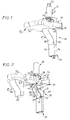
- the wiring conduit 10 intervening in upstream of the false ceiling 13 is a simple tube, of diameter D which extends more or less freely above this false ceiling 13.
- the wiring conduit 11 which intervenes downstream of the false ceiling 13 is, for example, and as shown, a chute, comprising, of usual way, a base 14 adapted to be leaned, and fixed, to a wall, not shown, from the room underlying the false ceiling 13, and a cover 15 adapted to close this base 14.
- the false ceiling 13 is formed of plates 16, which, for example, and as shown, rest on the horizontal wing of brackets here continuous 17 duly fixed to the wall of the room concerned, and to which it will be below systematically assimilated.
- connection, one to the other, of the two wiring conduits 10, 11 implies the use of an accessory specific, in this case an adapter 18.
- this adapter 18 comprises, on the one hand, a bottom 19, which, at one of its ends, and according to arrangements described in more detail subsequently, presents an opening 20 for the engagement of a first of wiring ducts 10, 11, in this case the wiring duct 10 intervening in upstream of the false ceiling 13, and at the other end of which the other of these conduits wiring 10, 11, in this case the wiring conduit 11 intervening downstream of the false ceiling 13, can be abutted, and, on the other hand, a cover 21, which, according to provisions also described in more detail later, covers at least partly the bottom 19.
- the opening 20 has a diameter at least equal to the diameter D of the wiring duct 10.
- the bottom 19 comprises, concentrically, several openings 20, of which only the most internal is hollowed out, while the others are than precut, and the outermost of which has a diameter adapted to the the largest possible diameter for the wiring duct 10.
- the bottom 19 has only one opening 20.
- the opening 20 of the bottom 19 of the adapter 18 is located upstream of a bottom reference plane (defined below), intended to be arranged at the lower face of the false ceiling, preferably at a sufficient distance from this plane to be upstream of the false ceiling 13 relative to outside, that is to say in relation to the underlying room.
- a bottom reference plane defined below
- the bottom 19 of the adapter 18 comprises, itself, under the reference plane, a base 22, by which it is suitable to be leaned against a wall, this base 22 forming for this purpose a bearing surface 23 substantially planar, and, above the reference plane, a console 24, which has the opening 20, with, connecting this base 22 to this console 24, at least one link arms; this single arm (or all of the arms if there are several) is not no wider than the base.
- two connecting flanks 25, which, set at a distance from each other, have identical configurations. They jointly form a link arm.
- the connecting flanks 25 are in one piece with the base 22 and the console 24, the entire bottom 19 forming one-piece molding.
- the connecting flanks 25 preferably extend each recessed with respect to the bearing surface 23 of the base 22, for crossing the horizontal wing (if it exists locally) of the corresponding square 17.
- this withdrawal extends from the base, starting from the latter.
- the link arms 25 each have, at their connection to the base 22, recessed on their edge closest to the bearing surface 23 of the latter, a notch 26 by which they are able to engage at least partly on the wing in question of square 17 concerned. This notch runs along the reference plane.
- connection 25 are in the form of flanges which are connected by a bottom so as to jointly form a U-shaped link arm which constitutes a channel insulating the wires, in particular with respect to the bracket 17.
- These sides are of contour appropriate, and they extend generally in bridge between the base 22 and the console 24.
- the base 22 of the bottom 19 of the adapter 18 generally forms a gutter 27, with a bottom 28 and two side wings 30, FIG. 2, and the link arms 25 extend each set back relative to the lateral wings 30 of this gutter 27.
- the reference plane is here materialized by the upper sections of the lateral wings 30 and / or the lower edges of the sides 25.
- the bottom 28 of the gutter 27 is, at less on a part of its course, curved, like a slide, while joining, by a flat part, at its end, the bearing surface 23.
- this bottom 28 is, locally, perforated, in its flat part, with at least one bore 31, for fixing the base 22 to the wall to which it is backed.
- At least one of the wings side 30 of the gutter 27 formed by the base 22 has, at its end the further from the associated console 24, at least one notch 32, for the cover positioning 21.
- the lateral wings 30 of the gutter 27 each have, in look at each other, such a notch 32.
- the console 24, for its part, has essentially a flange 33, which is perforated with its opening 20, and which extends for example substantially perpendicular to the bearing surface 23 of the base 22, and therefore substantially parallel to the false ceiling 13.
- the console 24 comprises, in in addition, level with the bearing surface 23 of the base 22, a sole 34, opposite from which its flange 33 extends cantilever, and by which it can, it also, be leaned against the wall concerned.
- this sole 34 is also hollowed out locally by at least one bore 35, for fixing the console 24 to this wall.
- two holes 35 can be provided at a distance from one of the other, parallel to the flange 33.
- the console 24 comprises, in besides, laterally, for its stiffening, two cheeks of triangulation 37 (they are also used to protect the cables), which connect its flange 33 to its sole 34, possibly following a profile which, at least locally, is curved.
- the link arms 25 are connected to the console 24 at the end of these triangulation cheeks 37, along the edge corresponding to these.
- the cover 21 has only one part, by which it is adapted to cover only the base 22 of the bottom 19.
- the cover 21 is reduced to a front wall 38, the profile of which follows that of the gutter 27 formed by the base 22, and with two dropped edges 39, which extend parallel to each other, and by which it is able to frame the base 22 of the bottom 19.
- the fallen edges 39 have, each, along their edge closest to the console 24, a step 40, for their engagement on the horizontal wing of the square 17 concerned.
- latching means are provided between the cover 21 and the base 22.
- these latching means imply the presence of notches 41 recessed on the outer surface of the wings side 30 of the gutter 27 formed by the base 22, and notches complementary, not visible in the figures, provided in relief correspondence on the internal surface of the lateral wings 39 of the cover 21.
- the cover 21 is larger than the notch 42 so as to hide the notch 42 (the smaller the notch, the smaller the cover can be).
- the bottom 19 of the adapter 18 is then fixed on the wall concerned using, or not, the notch 26 of its link arms 25 for its engagement on the wing horizontal of the bracket 17, and, thus, for its positioning relative to this square 17, and, therefore, relative to the plate 16, and / or using or not its holes 31 or 35 for fixing to the corresponding wall.
- the base 22 of the bottom 19 is located below the false ceiling 13 and its console 24 above it.
- the wiring conduit 10 is then connected to this console 24, engaging the latter in the corresponding opening 20 of this console 24.
- the plate 16 is then replaced, engaging it, by its notch 42, on the link arm 25 from the bottom 19.
- the cables or electrical conductors 12 are not protected by the cover 21 only below the false ceiling 13.
- the false ceiling 13 is made to pass through the cover 21 of the adapter 18 so that it completely covers the bottom 19 with which it is associated.
- the cover 21 includes then, successively, three parts, namely, a first end part 21A, by which it covers, as before, the base 22 of the bottom 19, a part intermediate 21B, by which it covers the link arm (s) 25 of this bottom 19, and a second end part 21C, by which it covers its console 24.
- the intermediate part 21B of the cover 21 is set back relative to its end parts 21A, 21C.
- Slots 26 and 40 linked to the presence of a square 17 are not essential if the false ceiling does not use this type of support or if this square is locally interrupted (at least in its horizontal wing).
- the link arm (the part U-shaped, or the set of flanks 25), which is not wider than the base, was longer than the thickness of the false ceiling.
- this is not necessary because, even if this arm is shorter than this thickness, it suffices to dig a cavity in the upper part of the false ceiling suitable for receiving the console, and we have the advantage of the invention consisting in having a notch 42, in the false ceiling which, at least near its lower surface, is not significantly wider than the base, advantageously narrower than the console.
Landscapes
- Engineering & Computer Science (AREA)
- Architecture (AREA)
- Civil Engineering (AREA)
- Structural Engineering (AREA)
- Details Of Indoor Wiring (AREA)
Applications Claiming Priority (2)
| Application Number | Priority Date | Filing Date | Title |
|---|---|---|---|
| FR0001795A FR2805095B1 (fr) | 2000-02-14 | 2000-02-14 | Adaptateur pour le raccordement de deux conduits de cablage intervenant de part et d'autre d'un faux-plafond |
| FR0001795 | 2000-02-14 |
Publications (2)
| Publication Number | Publication Date |
|---|---|
| EP1126570A1 true EP1126570A1 (de) | 2001-08-22 |
| EP1126570B1 EP1126570B1 (de) | 2009-05-27 |
Family
ID=8846967
Family Applications (1)
| Application Number | Title | Priority Date | Filing Date |
|---|---|---|---|
| EP01400345A Expired - Lifetime EP1126570B1 (de) | 2000-02-14 | 2001-02-09 | Adapter zur Verbindung von zwei Kabelrinnen an jeder Seite einer aufgehängten Decke |
Country Status (5)
| Country | Link |
|---|---|
| US (1) | US6479750B1 (de) |
| EP (1) | EP1126570B1 (de) |
| DE (1) | DE60138777D1 (de) |
| ES (1) | ES2329005T3 (de) |
| FR (1) | FR2805095B1 (de) |
Families Citing this family (5)
| Publication number | Priority date | Publication date | Assignee | Title |
|---|---|---|---|---|
| US8247694B2 (en) * | 2008-03-14 | 2012-08-21 | Yazaki Corporation | Protector structure for electric power feeding apparatus |
| US8093511B2 (en) * | 2009-08-26 | 2012-01-10 | Creality Ab | Ceiling suspension assembly |
| EP2886947B1 (de) * | 2013-12-20 | 2018-06-06 | Tego System Holding AB | Montagevorrichtung für ein elektriches Gerät auf einem Deckenbalkenträger |
| CN103997002A (zh) * | 2014-05-30 | 2014-08-20 | 杨永坚 | 一种用于集成吊顶的线路支架 |
| CA3176241A1 (en) * | 2020-05-13 | 2021-11-18 | GAF Energy LLC | Electrical cable passthrough |
Citations (3)
| Publication number | Priority date | Publication date | Assignee | Title |
|---|---|---|---|---|
| DE9010556U1 (de) * | 1990-07-13 | 1990-09-20 | H. E. Christensen ApS, Frederiksberg | Abschlußstück für einen auf einer Stützfläche montierten Kabelkanal |
| US5300731A (en) * | 1992-04-02 | 1994-04-05 | Hubbell Incorporated | Conduit adapter assembly |
| EP0802364A2 (de) * | 1996-04-19 | 1997-10-22 | Tehalit GmbH | Blende zum Kaschieren von Wanddurchbrüchen |
Family Cites Families (3)
| Publication number | Priority date | Publication date | Assignee | Title |
|---|---|---|---|---|
| US3609211A (en) * | 1970-08-28 | 1971-09-28 | Medland Enterprises | Duct with power and communications outlet |
| US4015397A (en) * | 1974-04-29 | 1977-04-05 | Textron, Inc. | Service poles and accessories |
| US4178468A (en) * | 1977-05-04 | 1979-12-11 | Square D Company | Duct post |
-
2000
- 2000-02-14 FR FR0001795A patent/FR2805095B1/fr not_active Expired - Fee Related
- 2000-05-04 US US09/563,836 patent/US6479750B1/en not_active Expired - Lifetime
-
2001
- 2001-02-09 ES ES01400345T patent/ES2329005T3/es not_active Expired - Lifetime
- 2001-02-09 DE DE60138777T patent/DE60138777D1/de not_active Expired - Lifetime
- 2001-02-09 EP EP01400345A patent/EP1126570B1/de not_active Expired - Lifetime
Patent Citations (3)
| Publication number | Priority date | Publication date | Assignee | Title |
|---|---|---|---|---|
| DE9010556U1 (de) * | 1990-07-13 | 1990-09-20 | H. E. Christensen ApS, Frederiksberg | Abschlußstück für einen auf einer Stützfläche montierten Kabelkanal |
| US5300731A (en) * | 1992-04-02 | 1994-04-05 | Hubbell Incorporated | Conduit adapter assembly |
| EP0802364A2 (de) * | 1996-04-19 | 1997-10-22 | Tehalit GmbH | Blende zum Kaschieren von Wanddurchbrüchen |
Also Published As
| Publication number | Publication date |
|---|---|
| ES2329005T3 (es) | 2009-11-20 |
| DE60138777D1 (de) | 2009-07-09 |
| EP1126570B1 (de) | 2009-05-27 |
| FR2805095B1 (fr) | 2002-04-05 |
| US6479750B1 (en) | 2002-11-12 |
| FR2805095A1 (fr) | 2001-08-17 |
Similar Documents
| Publication | Publication Date | Title |
|---|---|---|
| EP0343071A1 (de) | Tragstruktur zur auskragenden Befestigung eines Sanitärelements und ihre Stützpfosten | |
| EP0241325B1 (de) | Adapterträger für Elektrogeräte | |
| EP0734107B1 (de) | Winkelzubehörverbindungselement für Elektrokanal und Winkelzubehör dafür | |
| EP1149447B1 (de) | Gerätegehalter ,insbesondere für elektrisches gerät und damit ausgerüstetes gehäuse | |
| EP1126570B1 (de) | Adapter zur Verbindung von zwei Kabelrinnen an jeder Seite einer aufgehängten Decke | |
| EP1094581A1 (de) | Durchführungszubehör für Kabelkanal | |
| EP0851551B1 (de) | Verfahren und Vorrichtung zum Verbessern des Haltens eines Zubehörs mit Schnappbefestigung an einem Kabelrinnensockel | |
| WO1999052189A1 (fr) | Goulotte de cablage et accessoire susceptible d'être rapporte sur une telle goulotte de cablage | |
| EP0921616B1 (de) | Kabelrinneverbindungszusatz für Eckverbindung oder Abzweigung | |
| EP0267079B1 (de) | Abzweigungszubehör für Verkabelungsrohr | |
| EP1005127A1 (de) | Geräteträgereinrichtung Einzubringen auf einen Kabelkanalseite mit mehrteiliger Abdeckung | |
| EP0721245B1 (de) | Geräteträger für ein teilweise in einer Leitung versenktes Gehäuse, und Verfahren zu seiner Durchführung | |
| EP0702443B1 (de) | Geräteträgereinrichtung Einzubringen auf einen Kabelkanalkörper | |
| EP1164676A1 (de) | Vorrichtung zur Befestigung eines elektrischen Geräts auf einem Kabelkanal | |
| EP0875974B1 (de) | Unterputzdose in einer Wand geringer Dicke für elektrisches Gerät mit einer Leitungsklappeinführung | |
| EP0887903B1 (de) | Sockel für Kabelkanal mit einem V-förmigen Querschnitt, insbesondere Eckkanal oder Unterputzkanal | |
| EP0776078A1 (de) | Abzweigungszubehör für Elektroprofil, wie Wandkabelrinne | |
| EP0964494B1 (de) | Abzweigungszubehör für Elektroinstallation sowie Elektroinstallation | |
| FR2930684A1 (fr) | Accessoire de montage d'un bloc electrique dans un conduit de cheminement de cables ou de conducteurs electriques et ensemble electrique comprenant un bloc electrique ainsi qu'un tel accessoire | |
| EP0964495B1 (de) | Unterputzdose mit Körper und Fuss als Doseverlängerung insbesondere für elektrische Geräte | |
| EP1246333A1 (de) | Endstück für einen Führungskanal | |
| FR2761853A1 (fr) | Chassis de support a plaque de fond isolante, notamment pour appareillage electrique | |
| FR2744850A1 (fr) | Cadre de facade pour coffret, en particulier coffret electrique, et coffret comportant un tel cadre de facade | |
| FR2811152A1 (fr) | Dispositif pour la fixation semi-encastree d'au moins un appareillage dans un conduit de cablage de profondeur inferieure a celle de l'appareillage | |
| FR2753013A1 (fr) | Accessoire pour goulotte, notamment pour appareillage electrique |
Legal Events
| Date | Code | Title | Description |
|---|---|---|---|
| PUAI | Public reference made under article 153(3) epc to a published international application that has entered the european phase |
Free format text: ORIGINAL CODE: 0009012 |
|
| AK | Designated contracting states |
Kind code of ref document: A1 Designated state(s): AT BE CH CY DE DK ES FI FR GB GR IE IT LI LU MC NL PT SE TR Kind code of ref document: A1 Designated state(s): DE ES FR GB IT SE |
|
| AX | Request for extension of the european patent |
Free format text: AL;LT;LV;MK;RO;SI |
|
| 17P | Request for examination filed |
Effective date: 20011001 |
|
| AKX | Designation fees paid |
Free format text: DE ES FR GB IT SE |
|
| GRAP | Despatch of communication of intention to grant a patent |
Free format text: ORIGINAL CODE: EPIDOSNIGR1 |
|
| RTI1 | Title (correction) |
Free format text: ADAPTER FOR JOINING TWO CABLING DUCTS SITUATED ON EITHER SIDE OF A FALSE CEILING |
|
| RAP1 | Party data changed (applicant data changed or rights of an application transferred) |
Owner name: PLANET WATTOHM |
|
| GRAS | Grant fee paid |
Free format text: ORIGINAL CODE: EPIDOSNIGR3 |
|
| GRAA | (expected) grant |
Free format text: ORIGINAL CODE: 0009210 |
|
| AK | Designated contracting states |
Kind code of ref document: B1 Designated state(s): DE ES FR GB IT SE |
|
| REG | Reference to a national code |
Ref country code: GB Ref legal event code: FG4D Free format text: NOT ENGLISH |
|
| REF | Corresponds to: |
Ref document number: 60138777 Country of ref document: DE Date of ref document: 20090709 Kind code of ref document: P |
|
| REG | Reference to a national code |
Ref country code: SE Ref legal event code: TRGR |
|
| REG | Reference to a national code |
Ref country code: ES Ref legal event code: FG2A Ref document number: 2329005 Country of ref document: ES Kind code of ref document: T3 |
|
| PLBE | No opposition filed within time limit |
Free format text: ORIGINAL CODE: 0009261 |
|
| STAA | Information on the status of an ep patent application or granted ep patent |
Free format text: STATUS: NO OPPOSITION FILED WITHIN TIME LIMIT |
|
| PGFP | Annual fee paid to national office [announced via postgrant information from national office to epo] |
Ref country code: ES Payment date: 20100121 Year of fee payment: 10 |
|
| 26N | No opposition filed |
Effective date: 20100302 |
|
| PGFP | Annual fee paid to national office [announced via postgrant information from national office to epo] |
Ref country code: IT Payment date: 20100227 Year of fee payment: 10 Ref country code: FR Payment date: 20100312 Year of fee payment: 10 |
|
| PGFP | Annual fee paid to national office [announced via postgrant information from national office to epo] |
Ref country code: GB Payment date: 20100217 Year of fee payment: 10 Ref country code: DE Payment date: 20100225 Year of fee payment: 10 |
|
| PGFP | Annual fee paid to national office [announced via postgrant information from national office to epo] |
Ref country code: SE Payment date: 20100120 Year of fee payment: 10 |
|
| REG | Reference to a national code |
Ref country code: SE Ref legal event code: EUG |
|
| GBPC | Gb: european patent ceased through non-payment of renewal fee |
Effective date: 20110209 |
|
| REG | Reference to a national code |
Ref country code: FR Ref legal event code: ST Effective date: 20111102 |
|
| PG25 | Lapsed in a contracting state [announced via postgrant information from national office to epo] |
Ref country code: IT Free format text: LAPSE BECAUSE OF NON-PAYMENT OF DUE FEES Effective date: 20110209 |
|
| PG25 | Lapsed in a contracting state [announced via postgrant information from national office to epo] |
Ref country code: FR Free format text: LAPSE BECAUSE OF NON-PAYMENT OF DUE FEES Effective date: 20110228 |
|
| REG | Reference to a national code |
Ref country code: DE Ref legal event code: R119 Ref document number: 60138777 Country of ref document: DE Effective date: 20110901 |
|
| PG25 | Lapsed in a contracting state [announced via postgrant information from national office to epo] |
Ref country code: GB Free format text: LAPSE BECAUSE OF NON-PAYMENT OF DUE FEES Effective date: 20110209 |
|
| REG | Reference to a national code |
Ref country code: ES Ref legal event code: FD2A Effective date: 20120411 |
|
| PG25 | Lapsed in a contracting state [announced via postgrant information from national office to epo] |
Ref country code: ES Free format text: LAPSE BECAUSE OF NON-PAYMENT OF DUE FEES Effective date: 20110210 |
|
| PG25 | Lapsed in a contracting state [announced via postgrant information from national office to epo] |
Ref country code: SE Free format text: LAPSE BECAUSE OF NON-PAYMENT OF DUE FEES Effective date: 20110210 |
|
| PG25 | Lapsed in a contracting state [announced via postgrant information from national office to epo] |
Ref country code: DE Free format text: LAPSE BECAUSE OF NON-PAYMENT OF DUE FEES Effective date: 20110901 |