EP1126577A1 - Machine électrique - Google Patents
Machine électrique Download PDFInfo
- Publication number
- EP1126577A1 EP1126577A1 EP20010250051 EP01250051A EP1126577A1 EP 1126577 A1 EP1126577 A1 EP 1126577A1 EP 20010250051 EP20010250051 EP 20010250051 EP 01250051 A EP01250051 A EP 01250051A EP 1126577 A1 EP1126577 A1 EP 1126577A1
- Authority
- EP
- European Patent Office
- Prior art keywords
- shaft
- magnet system
- electrical machine
- aforementioned
- rotor
- Prior art date
- Legal status (The legal status is an assumption and is not a legal conclusion. Google has not performed a legal analysis and makes no representation as to the accuracy of the status listed.)
- Withdrawn
Links
- 230000001360 synchronised effect Effects 0.000 claims abstract description 19
- 239000000696 magnetic material Substances 0.000 claims abstract description 8
- 238000004804 winding Methods 0.000 claims description 12
- 229910000831 Steel Inorganic materials 0.000 claims description 4
- 239000010959 steel Substances 0.000 claims description 4
- 239000004744 fabric Substances 0.000 claims description 2
- 239000003365 glass fiber Substances 0.000 claims description 2
- 239000000853 adhesive Substances 0.000 abstract 1
- 230000001070 adhesive effect Effects 0.000 abstract 1
- 230000003313 weakening effect Effects 0.000 description 5
- 229910052751 metal Inorganic materials 0.000 description 4
- 239000002184 metal Substances 0.000 description 4
- 238000011161 development Methods 0.000 description 3
- 230000018109 developmental process Effects 0.000 description 3
- 230000001965 increasing effect Effects 0.000 description 3
- 238000005304 joining Methods 0.000 description 3
- 238000003860 storage Methods 0.000 description 3
- 239000004020 conductor Substances 0.000 description 2
- 230000005284 excitation Effects 0.000 description 2
- 230000004907 flux Effects 0.000 description 2
- 238000004519 manufacturing process Methods 0.000 description 2
- VYZAMTAEIAYCRO-UHFFFAOYSA-N Chromium Chemical compound [Cr] VYZAMTAEIAYCRO-UHFFFAOYSA-N 0.000 description 1
- 239000000956 alloy Substances 0.000 description 1
- 229910045601 alloy Inorganic materials 0.000 description 1
- 229910052804 chromium Inorganic materials 0.000 description 1
- 239000011651 chromium Substances 0.000 description 1
- 230000000052 comparative effect Effects 0.000 description 1
- 230000006835 compression Effects 0.000 description 1
- 238000007906 compression Methods 0.000 description 1
- 230000002950 deficient Effects 0.000 description 1
- 238000005516 engineering process Methods 0.000 description 1
- 238000010438 heat treatment Methods 0.000 description 1
- 230000001771 impaired effect Effects 0.000 description 1
- 230000001939 inductive effect Effects 0.000 description 1
- 238000009434 installation Methods 0.000 description 1
- 239000000463 material Substances 0.000 description 1
- 229910001172 neodymium magnet Inorganic materials 0.000 description 1
- 238000003825 pressing Methods 0.000 description 1
- 230000011218 segmentation Effects 0.000 description 1
- 238000010792 warming Methods 0.000 description 1
Images

Classifications
-
- H—ELECTRICITY
- H02—GENERATION; CONVERSION OR DISTRIBUTION OF ELECTRIC POWER
- H02K—DYNAMO-ELECTRIC MACHINES
- H02K1/00—Details of the magnetic circuit
- H02K1/06—Details of the magnetic circuit characterised by the shape, form or construction
- H02K1/22—Rotating parts of the magnetic circuit
- H02K1/27—Rotor cores with permanent magnets
- H02K1/2706—Inner rotors
- H02K1/272—Inner rotors the magnetisation axis of the magnets being perpendicular to the rotor axis
- H02K1/274—Inner rotors the magnetisation axis of the magnets being perpendicular to the rotor axis the rotor consisting of two or more circumferentially positioned magnets
- H02K1/2753—Inner rotors the magnetisation axis of the magnets being perpendicular to the rotor axis the rotor consisting of two or more circumferentially positioned magnets the rotor consisting of magnets or groups of magnets arranged with alternating polarity
- H02K1/278—Surface mounted magnets; Inset magnets
- H02K1/2781—Magnets shaped to vary the mechanical air gap between the magnets and the stator
-
- H—ELECTRICITY
- H02—GENERATION; CONVERSION OR DISTRIBUTION OF ELECTRIC POWER
- H02K—DYNAMO-ELECTRIC MACHINES
- H02K1/00—Details of the magnetic circuit
- H02K1/06—Details of the magnetic circuit characterised by the shape, form or construction
- H02K1/12—Stationary parts of the magnetic circuit
- H02K1/14—Stator cores with salient poles
- H02K1/146—Stator cores with salient poles consisting of a generally annular yoke with salient poles
- H02K1/148—Sectional cores
-
- H—ELECTRICITY
- H02—GENERATION; CONVERSION OR DISTRIBUTION OF ELECTRIC POWER
- H02K—DYNAMO-ELECTRIC MACHINES
- H02K21/00—Synchronous motors having permanent magnets; Synchronous generators having permanent magnets
- H02K21/02—Details
Definitions
- the invention relates to an electrical machine, in particular synchronous machine, according to the preamble of Claim 1.
- the Winding usually consists of pre-wound wire spools through the rotor facing slot slots inserted into the grooves become. There may be overlaps in the pre-wound coils of the wires cannot be excluded. Still requires the protection of the wires from the edges of the laminated core Arrangement of stable laminates in the slot slot during of inlay. The width of the usable slot is therefore at least the sum of twice the wire size plus that twice the thickness of the laminate.
- Grooves in the stator create in the moving rotor pulsating magnetic fields, which in turn create eddy currents Frequency corresponding to the product of speed times number of uses induce. Especially with permanently excited electric motors and generators with high speeds are the eddy current losses the main cause of warming of the Rotors.
- the object of the invention is a Propose synchronous machine with which the constructive Effort is significantly reduced and assembly is simplified as well as eddy currents are reduced.
- This task is based on an electric motor, in particular synchronous motor, of the type mentioned in the introduction solved by the characterizing features of claim 1.
- one according to the invention is distinguished electrical machine, in particular synchronous machine, thereby from that the magnet system without a carrier system on the Shaft is arranged.
- the magnet system is for the excitation of a magnetic field trained, for example with excitation coils.
- the magnet system advantageously comprises at least a permanent magnet so that a synchronous motor with particularly low design effort is realized. So the shaft is ready for installation in a housing prepared when the storage and the permanent magnet on the shaft is mounted.
- the magnet system is included bonded to the shaft. This will be more advantageous Way ensures that the magnet system even at higher Speeds remains firmly connected to the shaft. At the same time do not occur due to the realized connection Tensions in the magnet system or in the Permanent magnets.
- connection of the magnet system with the Shaft preferably realized by screwing.
- connection of the magnet system with the Shaft preferably realized by screwing.
- magnetic material in from the shaft predetermined areas are let in, the magnetic material cast, sintered or otherwise with the shaft is associated.
- a combination of the corresponding connections are also possible.
- the shaft in the area of the magnet system at least partially a hard magnetic material, so that the shaft itself in Area of the magnet system is magnetizable. This will advantageously the manufacturing effort for the shaft further reduced.
- the shaft advantageously exists at least in the area of the magnet system mostly made of soft magnetic Material so that the shaft to guide the magent river is usable. This is a simple Guaranteed so-called magnetic connection, which at the state of Technology in general via the soft magnetic carrier system he follows.
- the shaft must be manufactured care must be taken that the soft magnetic properties of the Wave in the area of the magnet system not by means of heat treatment or mechanical processing is impaired. For this reason, steels with less can, for example Chromium shares can be used accordingly advantageously.
- An inner diameter of the front bearing is preferred larger than an outer diameter of the rotor, including an outer diameter of the magnet system, so that for Assembly of the front bearing or Synchronous machine, for example, both the front bearing, the Magnet system as well as the rear bearing from one side of the Shaft mountable or the two bearings also magnet system mounted on the rotor can be removed.
- the flange can be one significantly larger diameter than the inside diameter of the own front bearing.
- the wave, including the flange, from a precisely manufactured Pieces can be made or a separate flange can be made the shaft.
- Synchronous motor is thus guaranteed to be a damaged or defective front bearing without dismantling the Magnet system or the output-side flange of the shaft is interchangeable via the rear area of the rotor.
- the shaft advantageously has at least in the region of the Magnetic system a cross section with a circular or polygonal outer shape and the magnet system one corresponding circular or polygonal recess. This is used, for example, for brittle permanent magnets comparatively large diameters and thin walls a comparatively simple manufacture and assembly guaranteed.
- the magnet system advantageously comprises a bandage, so that the safety of the magnet system arrangement even at high Speeds or stresses is guaranteed. So will a hurling away or breaking the Magnet system prevented in an advantageous manner.
- the stator of the electrical machine exists advantageously from pole segments, especially after the winding from the yoke side preferably through Yoke segments or a yoke ring magnetically with one another get connected. By wrapping from the yoke side slot slots can be largely avoided. At a almost constant distance from soft magnetic parts of the The rotor and the stator are subject to fluctuations in the reactance Air gap and eddy currents caused thereby in the rotor largely avoided. The rotor stays in spite of the good ones electrical conductivity of the unbleached wave cool.
- the field weakening factor is the ratio of Corner point speed to the maximum speed, with the Corner point speed the induced voltage roughly the Supply voltage corresponds.
- the field weakening area in particular a synchronous machine with air gap magnets can be significantly enlarged on the one hand and on the other hand will significantly reduce the for field weakening required currents reached.
- the pole and yoke segments are preferably larger prefabricated electrical machines as separate sheet metal packages.
- the soft magnetic segments can also be used a bridge between the pole pieces connected from a round blank as a star-shaped sheet metal cut or from a band as comb-shaped strips can be produced.
- Such one The strip then advantageously becomes an annular one Sheet metal package coiled, the bend of the strip in the thin webs between the segments.
- the segmentation of the Stator laminated core for example, with electrical sheets advantageous grain orientation are used, the in addition, the magnetic losses compared to about 70% reduce non-oriented electrical sheets.
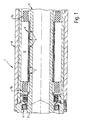
- a synchronous machine 1 which is shown in Figure 1, has, for example, a tubular shaft 2. in the middle area of the shaft 2 are individual permanent magnets 3 arranged. The permanent magnets 3 are on the shaft 2 glued. Throwing away is by means of a bandage 9 or breaking the permanent magnets 3 even at high Engine speeds prevented.
- FIG. 1 a front bearing 4 is shown in FIG. 1, which has an inside diameter larger than an outer diameter of the rotor 5 in the middle or in the rear area of the shaft 2. Hence can the front bearing 4 over the area of Permanent magnets 3 can be assembled or disassembled.
- Figure 1 shows in addition to other constructive Elements a stator 6, two end windings 7a, 7b and one Motor housing 8.
- Fig. 2 shows the cross section of a four-pole Synchronous machine with radially inside the stator 10 arranged rotor 11.
- the rotor 11 has at the air gap 12 arranged permanent magnets 13 - preferably from a NdFeB alloy - and a hollow shaft 14 made of magnetizable Full material on.
- the stator laminated core consists of twelve Pole segments 15 and twelve yoke segments 16 grain-oriented electrical sheets, the magnetic Preferred direction of the pole segments 15 radially and that of Yoke segments 16 is tangential. After inserting the Winding 17 between by a device in it final position held pole segments 15 are the Yoke segments 16 inserted radially from the outside and to the Joining gaps 18 welded to the pole segments 15.
- the trapezoidal grooves 19 form towards the air gap 12 narrow slot slots 20.
- the width of the slot slots 20 on the narrowest point is smaller than the air gap width that the Distance between the permanent magnets 13 and Pole segments 15 corresponds. Through surface tolerances can adjacent pole segments 15 in the slot slots 20 also meet directly.
- To increase the Self-inductance point pole shoes 21 to the slot 20 facing sides have a radial height that is greater than the height required to guide the magnetic flux.
- the pole shoes 21 of electrically generated Magnetic fields used up to the saturation limit.
- the shape of the slot slots 20 or pole shoes 21 can be one Set high self-inductance at higher speeds the terminal voltage due to the inductive voltage drop limited.
- About the width of the joining gap 18 between the The self-inductance can also be segments 15, 16 to be influenced.
Landscapes
- Engineering & Computer Science (AREA)
- Power Engineering (AREA)
- Iron Core Of Rotating Electric Machines (AREA)
- Permanent Field Magnets Of Synchronous Machinery (AREA)
Applications Claiming Priority (4)
| Application Number | Priority Date | Filing Date | Title |
|---|---|---|---|
| DE10007064 | 2000-02-16 | ||
| DE10007064 | 2000-02-16 | ||
| DE10018962 | 2000-04-17 | ||
| DE10018962 | 2000-04-17 |
Publications (1)
| Publication Number | Publication Date |
|---|---|
| EP1126577A1 true EP1126577A1 (fr) | 2001-08-22 |
Family
ID=26004369
Family Applications (1)
| Application Number | Title | Priority Date | Filing Date |
|---|---|---|---|
| EP20010250051 Withdrawn EP1126577A1 (fr) | 2000-02-16 | 2001-02-16 | Machine électrique |
Country Status (2)
| Country | Link |
|---|---|
| EP (1) | EP1126577A1 (fr) |
| DE (1) | DE10107760A1 (fr) |
Families Citing this family (2)
| Publication number | Priority date | Publication date | Assignee | Title |
|---|---|---|---|---|
| DE102005027953A1 (de) * | 2005-06-16 | 2006-12-28 | Siemens Ag | Permanentmagneterregte elektrische Maschine mit Rotorkühlung |
| DE102008043661A1 (de) * | 2008-11-12 | 2010-05-20 | Robert Bosch Gmbh | Welle für eine elektrische Maschine, insbesondere für einen Motorgenerator |
Citations (8)
| Publication number | Priority date | Publication date | Assignee | Title |
|---|---|---|---|---|
| US4587721A (en) * | 1984-03-27 | 1986-05-13 | General Electric Company | Method of assembling a rotatable assembly, apparatus and method of operating such |
| US4642502A (en) * | 1986-04-24 | 1987-02-10 | General Motors Corporation | Dynamoelectric machine with permanent magnet and magnet mounting surface arrangement |
| DE8803372U1 (de) * | 1988-03-12 | 1988-04-28 | Frankl & Kirchner GmbH & Co KG Fabrik für Elektromotoren u. elektrische Apparate, 6830 Schwetzingen | Rotor für eine permanent-magnetisch erregte elektrische Maschine |
| JPH06253515A (ja) * | 1993-02-24 | 1994-09-09 | Matsushita Refrig Co Ltd | 自己始動形永久磁石式同期電動機の回転子 |
| US5506460A (en) * | 1993-01-14 | 1996-04-09 | Patent-Treuhand-Gesellschaft F. Elektrische Gluehlampen Mbh | Precision drive system for independently driven coaxial shafts, particularly to make coiled electric lamp filaments |
| EP0748025A2 (fr) * | 1995-06-07 | 1996-12-11 | Matsushita Electric Industrial Co., Ltd. | Stator de moteur électrique et sa fabrication |
| JPH1051985A (ja) * | 1996-08-02 | 1998-02-20 | Shinko Electric Co Ltd | 高速同期発電機のロータシュリンクリングとその製造方法 |
| US5945751A (en) * | 1991-06-28 | 1999-08-31 | Papst Licensing Gmbh | Disk storage device having a spindle driving motor |
-
2001
- 2001-02-16 DE DE10107760A patent/DE10107760A1/de not_active Withdrawn
- 2001-02-16 EP EP20010250051 patent/EP1126577A1/fr not_active Withdrawn
Patent Citations (8)
| Publication number | Priority date | Publication date | Assignee | Title |
|---|---|---|---|---|
| US4587721A (en) * | 1984-03-27 | 1986-05-13 | General Electric Company | Method of assembling a rotatable assembly, apparatus and method of operating such |
| US4642502A (en) * | 1986-04-24 | 1987-02-10 | General Motors Corporation | Dynamoelectric machine with permanent magnet and magnet mounting surface arrangement |
| DE8803372U1 (de) * | 1988-03-12 | 1988-04-28 | Frankl & Kirchner GmbH & Co KG Fabrik für Elektromotoren u. elektrische Apparate, 6830 Schwetzingen | Rotor für eine permanent-magnetisch erregte elektrische Maschine |
| US5945751A (en) * | 1991-06-28 | 1999-08-31 | Papst Licensing Gmbh | Disk storage device having a spindle driving motor |
| US5506460A (en) * | 1993-01-14 | 1996-04-09 | Patent-Treuhand-Gesellschaft F. Elektrische Gluehlampen Mbh | Precision drive system for independently driven coaxial shafts, particularly to make coiled electric lamp filaments |
| JPH06253515A (ja) * | 1993-02-24 | 1994-09-09 | Matsushita Refrig Co Ltd | 自己始動形永久磁石式同期電動機の回転子 |
| EP0748025A2 (fr) * | 1995-06-07 | 1996-12-11 | Matsushita Electric Industrial Co., Ltd. | Stator de moteur électrique et sa fabrication |
| JPH1051985A (ja) * | 1996-08-02 | 1998-02-20 | Shinko Electric Co Ltd | 高速同期発電機のロータシュリンクリングとその製造方法 |
Non-Patent Citations (2)
| Title |
|---|
| PATENT ABSTRACTS OF JAPAN vol. 018, no. 652 (E - 1642) 12 December 1994 (1994-12-12) * |
| PATENT ABSTRACTS OF JAPAN vol. 1998, no. 06 30 April 1998 (1998-04-30) * |
Also Published As
| Publication number | Publication date |
|---|---|
| DE10107760A1 (de) | 2001-09-06 |
Similar Documents
| Publication | Publication Date | Title |
|---|---|---|
| EP1570564B1 (fr) | Machine electrique, en particulier moteur synchrone sans balais | |
| DE69827299T2 (de) | Elektrischer motor oder generator | |
| DE19728172C2 (de) | Elektrische Maschine mit weichmagnetischen Zähnen und Verfahren zu ihrer Herstellung | |
| DE102019206460B3 (de) | Drehende Mehrphasen-Transversalflussmaschine | |
| DE102010061784A1 (de) | Optimierter Speichenrotor | |
| DE19503610C2 (de) | Mehrphasige und vielpolige, elektrisch kommutierbare Maschine und Verfahren zur Herstellung des Ständers | |
| EP2448096A1 (fr) | Machine électrique à excitation permanente | |
| EP2768117A1 (fr) | Rotor d'une machine à reluctance | |
| DE4138014C1 (en) | Electromechanical power converter in rotary or linear form - has permanent magnets assembled in rotor driven by AC stator winding with pole elements | |
| DE102018200077A1 (de) | Rotor für einen bürstenlosen Gleichstrommotor, insbesondere für einen Innenläufer-Elektromotor, und Elektromotor mit einem solchen Rotor | |
| EP2507894B1 (fr) | Machine électrique excitée par des aimants permanents | |
| WO2011151138A2 (fr) | Machine électrique générant moins de bruit | |
| EP1126577A1 (fr) | Machine électrique | |
| DE19525346C2 (de) | Ringkern-Synchronmaschine | |
| DE10163544A1 (de) | Elektromotor und Verfahren zu dessen Herstellung | |
| WO1998043339A1 (fr) | Machine a poles a griffes | |
| DE20103661U1 (de) | Elektrische Maschine | |
| DE19648758A1 (de) | Dauermagnetisch erregte elektrische Maschine mit Rotorrückschluß | |
| DE9114582U1 (de) | Elektrische Maschine | |
| EP1233497B1 (fr) | Machine électrique excitée par aimant permanent | |
| WO2008034792A1 (fr) | Machine synchrone | |
| DE10031349A1 (de) | Elementbauweise bei TFM | |
| WO2011036135A1 (fr) | Machine électrique comportant un rotor à excitation hybride | |
| DE3511408A1 (de) | Umlaufende dynamoelektrische induktions-verbundmaschine | |
| DE69832832T2 (de) | Vorrichtung und Verfahren zum Erzeugen von Elektrizität |
Legal Events
| Date | Code | Title | Description |
|---|---|---|---|
| PUAI | Public reference made under article 153(3) epc to a published international application that has entered the european phase |
Free format text: ORIGINAL CODE: 0009012 |
|
| AK | Designated contracting states |
Kind code of ref document: A1 Designated state(s): AT BE CH CY DE DK ES FI FR GB GR IE IT LI LU MC NL PT SE TR |
|
| AX | Request for extension of the european patent |
Free format text: AL;LT;LV;MK;RO;SI |
|
| 17P | Request for examination filed |
Effective date: 20010908 |
|
| 17Q | First examination report despatched |
Effective date: 20020208 |
|
| AKX | Designation fees paid |
Free format text: AT BE CH CY DE DK ES FI FR GB GR IE IT LI LU MC NL PT SE TR |
|
| STAA | Information on the status of an ep patent application or granted ep patent |
Free format text: STATUS: THE APPLICATION IS DEEMED TO BE WITHDRAWN |
|
| 18D | Application deemed to be withdrawn |
Effective date: 20030517 |