EP1126597B1 - Méthode pour la détection d'un décalage de niveau continu prédéterminé dans un système audio pour automobile - Google Patents
Méthode pour la détection d'un décalage de niveau continu prédéterminé dans un système audio pour automobile Download PDFInfo
- Publication number
- EP1126597B1 EP1126597B1 EP20010301127 EP01301127A EP1126597B1 EP 1126597 B1 EP1126597 B1 EP 1126597B1 EP 20010301127 EP20010301127 EP 20010301127 EP 01301127 A EP01301127 A EP 01301127A EP 1126597 B1 EP1126597 B1 EP 1126597B1
- Authority
- EP
- European Patent Office
- Prior art keywords
- predetermined
- audio
- clip
- predetermined threshold
- offset
- Prior art date
- Legal status (The legal status is an assumption and is not a legal conclusion. Google has not performed a legal analysis and makes no representation as to the accuracy of the status listed.)
- Expired - Lifetime
Links
- 238000000034 method Methods 0.000 title claims description 13
- 230000005236 sound signal Effects 0.000 claims description 6
- 238000005070 sampling Methods 0.000 claims description 2
- 239000003990 capacitor Substances 0.000 description 5
- 239000000523 sample Substances 0.000 description 5
- 238000010586 diagram Methods 0.000 description 2
- 238000009825 accumulation Methods 0.000 description 1
- 230000003750 conditioning effect Effects 0.000 description 1
- 230000007812 deficiency Effects 0.000 description 1
- 238000001514 detection method Methods 0.000 description 1
Images
Classifications
-
- H—ELECTRICITY
- H03—ELECTRONIC CIRCUITRY
- H03F—AMPLIFIERS
- H03F1/00—Details of amplifiers with only discharge tubes, only semiconductor devices or only unspecified devices as amplifying elements
- H03F1/52—Circuit arrangements for protecting such amplifiers
-
- H—ELECTRICITY
- H03—ELECTRONIC CIRCUITRY
- H03F—AMPLIFIERS
- H03F1/00—Details of amplifiers with only discharge tubes, only semiconductor devices or only unspecified devices as amplifying elements
- H03F1/30—Modifications of amplifiers to reduce influence of variations of temperature or supply voltage or other physical parameters
-
- H—ELECTRICITY
- H03—ELECTRONIC CIRCUITRY
- H03F—AMPLIFIERS
- H03F1/00—Details of amplifiers with only discharge tubes, only semiconductor devices or only unspecified devices as amplifying elements
- H03F1/32—Modifications of amplifiers to reduce non-linear distortion
Definitions
- the present invention relates in general to detecting a DC offset in an automotive audio system, and, more specifically, to use of a diagnostic signal from a power amplifier to determine output conditions of the power amplifier as they are affected by a DC offset.
- Automotive audio systems typically have a power amplifier intended to amplify AC signals, but which will amplify any signal which is presented at the amplifier's input. Audio speakers, (normally 4 ohms), which are attached to the amplifier can be damaged by certain amounts of DC current. Capacitors are normally used on an input side of the amplifier to remove any DC offset in the amplifier input signal, thereby preventing DC current from flowing to the speakers. In the event these capacitors fail or are inadvertently not present, there can be substantial damage caused to the amplifier and/or the speakers. Currently, most automotive power amplifiers have protection for shorts but not for DC offsets.
- the present invention overcomes the deficiencies of the prior art by providing automatic detection of a DC offset.
- the method detects a predetermined DC offset in an audio signal provided by an audio processor unit to an audio power amplifier, wherein the audio amplifier provides a clip detect signal back to the audio processor unit.
- the method begins by sampling the clip detect signal at a predetermined rate during a predetermined time interval to collect a predetermined number of samples. Then, a number of active clip detects are counted during the predetermined time interval. Next, the counted number is compared to a predetermined threshold and the predetermined DC offset is detected if the counted number exceeds the predetermined threshold.
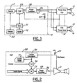
- FIG 1 shows an automotive audio system including an audio processing unit or head unit 10 and power amplifiers 11 and 14 driving speakers 12, 13, 15 and 16. Power amps 11 and 14 each drive left and right stereo speakers for front and rear speakers sets, respectively.
- Processing unit 10 includes an audio source 17 such as a radio tuner, cassette player, or compact disc player.
- An audio signal from source 17 is provided to an input of a digital signal processor (DSP) 20 which outputs left and right stereo signals.
- DSP digital signal processor
- Capacitors 26 and 27 are located between a power condition circuit 28 and power amplifier 14 and 11.
- Power conditioning circuit 28 includes digital-to-analog converter circuits for converting the DSP output to an analog signal. The capacitors allow AC signals to flow while preventing any DC signal flow, thus preventing DC offset in the amplified signals. In the event these capacitors are shorted, damaged, or missing, the speakers will be subjected to DC current which could potentially cause damage.
- a microcontroller unit (MCU) 21 communicates with DSP 20 and source 17 to control operation of the audio system.
- MCU 21 receives input commands from inputs 22 which may include push button operator controls or an interface to a multiplex network whereby commands may be received from other locations.
- a display 23 is connected to MCU 21 for displaying status of the audio processing unit to allow adjustment of audio parameters such as volume, balance, and fade.
- Power amps 11 and 14 provide outputs from a clip detector.
- the clip detector outputs indicate moments when clipping occurs in the output signal of the respective power amplifiers.
- the clip detect outputs of power amps 11 and 14 are connected together and to a pull-up resistor 24 and an input of DSP 20 in audio processing unit 10.
- the clip detect outputs of power amp 11 and 14 are configured to provide a current sink(i.e., a direct connection to ground) when clipping occurs.
- a current sink i.e., a direct connection to ground
- Figure 2 shows a DSP limiter function in which signal level is reduced in response to clipping.
- a clip detect signal provided from power amp 11 in conjunction with a pull-up resistor 25 is input to DSP 20 and is used in a limiter calculation which relates the severity of clipping with a particular limiter value. Specifically, the limiter value is reduced from a maximum value of 1.0 to a possible minimum value of 0.1 at a predetermined attack rate during clipping and is restored toward 1.0 at a slower decay rate when clipping is not present.
- a limiter calculation 70 produces a limiter value 71 which is stored in DSP 20 and is provided as a multiplier input to a multiplier 72 to reduce the volume command. The output of multiplier 72 is provided to a multiplier 73 which multiplies the audio signal which is then provided to power amplifier 11.
- the present invention analyzes clipping to determine if a DC offset is present.
- the clip detect outputs are monitored for active states during normal operation.
- Software routines, for example, in DSP 20 utilize a timer and a counter to sample and count a number of active clip detects occurring during a predetermined time interval.
- a hardware/analog circuit counter and timer can also be used to monitor the clip detect outputs.
- a predetermined rate is used to determine when to sample the clip detect output.
- the predetermined rate can be a cycle time of MCU 21, such as every 26 microseconds, for example. If the clip detect output is active when a sample is taken then the counter is incremented. Accumulation of a predetermined number of samples, such as 1000, is used to determine when to compare the counter to a predetermined threshold.
- a predetermined time interval is determined by a minimum frequency that can produce clipping. If the predetermined rate is 26 microseconds then a predetermined time interval for 1000 samples will be 1000•26•10 -6 or 26 milliseconds. This equals about 38 Hz and is the lowest frequency that will be detected if and when it causes clipping.
- the predetermined threshold can vary depending on the characteristics of the amplifier and the clip detect.
- Values from about 30 percent to about 50 percent of the total number of samples has been found to uniquely identify presence of a DC offset, for example. These values are typical because a normal signal without DC offset can clip based on the nature of audio signals and a maximum output of the audio amplifier.
- a normal clipping rate is about 10 to 15 percent. Any clipping rate above the normal clipping rate is considered unusual and indicates a DC offset.
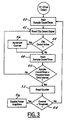
- FIG. 3 shows a method of detecting a DC offset in an audio power amplifier.
- a sample count/timer is started.
- a clip detect signal is sampled.
- a counter is incremented in step 46. If the clip detect is not active in step 44 or after the counter is incremented in step 46 the timer is read in step 48. If the timer has not exceeded a predetermined timer interval in step 50 then steps 42-50 are repeated until the timer exceeds the predetermined time interval. After the timer exceeds the predetermined time interval the counter is read in step 52.
- the counter reading is compared to a predetermined threshold and if the counter reading exceeds the predetermined threshold then the power amplifier is disabled in step 56 else the method is repeated starting at step 40.
Landscapes
- Engineering & Computer Science (AREA)
- Power Engineering (AREA)
- Physics & Mathematics (AREA)
- Nonlinear Science (AREA)
- Amplifiers (AREA)
Claims (8)
- Une méthode pour détecter un décalage de courant continu dans un signal audio fourni par un circuit de traitement des signaux sonores à un amplificateur de puissance audio, dans laquelle ledit amplificateur audio fournit un signal de détection de crêtes ou d'écrêtage en retour audit circuit de traitement des signaux sonores, ladite méthode comprenant les étapes de :échantillonner ledit signal de détection d'écrêtage ou de crêtes selon un taux prédéterminé pendant un intervalle de temps prédéterminé pour collecter un nombre d'échantillons prédéterminé ;compter un nombre de détections actives de crêtes ou d'écrêtage pendant ledit intervalle de temps prédéterminé ;comparer ledit nombre compté avec une limite prédéterminée ; etidentifier la présence dudit décalage de courant continu si ledit nombre compté dépasse ladite limite prédéterminée.
- La méthode selon la revendication 1, dans laquelle ledit circuit de traitement des signaux sonores comprend un microprocesseur et dans laquelle ledit taux prédéterminé correspond à au moins un cycle de la cadence dudit microprocesseur.
- La méthode selon la revendication 1, dans laquelle ladite limite prédéterminée est d'au moins 30 % dudit nombre d'échantillons prédéterminé.
- La méthode selon la revendication 1, dans laquelle une faute est rapportée à ladite installation principale si ledit nombre compté dépasse ladite limite prédéterminée.
- La méthode selon la revendication 1, dans laquelle ledit intervalle de temps prédéterminé est au moins aussi important qu'une période correspondant à une fréquence la moins élevée amplifiée par ledit amplificateur de puissance audio.
- La méthode selon la revendication 1, dans laquelle ladite limite prédéterminée est comprise entre environ 300 et environ 500 instances actives d'écrêtage ou crêtes effectives, parmi 1000 instances actives d'écrêtage ou crêtes effectives possibles.
- La méthode selon la revendication 1, dans laquelle ledit amplificateur de puissance audio est mis hors - service si ledit nombre compté dépasse ladite limite prédéterminée.
- Un système pour détecter un décalage de courant continu dans un signal audio fourni par un circuit de traitement des signaux sonores à un amplificateur audio, dans lequel ledit amplificateur audio fournit un signal de détection d'écrêtage ou de crêtes en retour audit circuit de traitement des signaux sonores, ledit système comprenant :dans lequel la présence dudit décalage de courant continu est identifiée si ledit compteur excède ladite limite prédéterminée.un chronomètre pour échantillonner ladite détection d'écrêtage ou de crêtes dans un intervalle de temps prédéterminé jusqu'à ce qu'un nombre d'échantillons prédéterminé soit atteint ;un compteur comptant les détections actives d'écrêtage ou de crêtes ; etun comparateur comparant lesdites détections actives d'écrêtage ou de crêtes comptées avec une limite prédéterminée lorsque ledit nombre d'échantillons prédéterminé est atteint ;
Applications Claiming Priority (2)
| Application Number | Priority Date | Filing Date | Title |
|---|---|---|---|
| US50530500A | 2000-02-17 | 2000-02-17 | |
| US505305 | 2000-02-17 |
Publications (3)
| Publication Number | Publication Date |
|---|---|
| EP1126597A2 EP1126597A2 (fr) | 2001-08-22 |
| EP1126597A3 EP1126597A3 (fr) | 2004-01-02 |
| EP1126597B1 true EP1126597B1 (fr) | 2005-04-20 |
Family
ID=24009785
Family Applications (1)
| Application Number | Title | Priority Date | Filing Date |
|---|---|---|---|
| EP20010301127 Expired - Lifetime EP1126597B1 (fr) | 2000-02-17 | 2001-02-08 | Méthode pour la détection d'un décalage de niveau continu prédéterminé dans un système audio pour automobile |
Country Status (2)
| Country | Link |
|---|---|
| EP (1) | EP1126597B1 (fr) |
| DE (1) | DE60110136T2 (fr) |
Family Cites Families (3)
| Publication number | Priority date | Publication date | Assignee | Title |
|---|---|---|---|---|
| JPS5425145A (en) * | 1977-07-28 | 1979-02-24 | Sony Corp | Detection circuit for unbalanced dc voltage of output amplifier on two-power- supply system |
| US5255324A (en) * | 1990-12-26 | 1993-10-19 | Ford Motor Company | Digitally controlled audio amplifier with voltage limiting |
| JP4121200B2 (ja) * | 1998-10-30 | 2008-07-23 | サンヨー・オートメディア・センディリアン・バハド | Btl電力増幅器におけるスピーカー保護回路 |
-
2001
- 2001-02-08 EP EP20010301127 patent/EP1126597B1/fr not_active Expired - Lifetime
- 2001-02-08 DE DE2001610136 patent/DE60110136T2/de not_active Expired - Fee Related
Also Published As
| Publication number | Publication date |
|---|---|
| DE60110136T2 (de) | 2006-03-02 |
| EP1126597A3 (fr) | 2004-01-02 |
| EP1126597A2 (fr) | 2001-08-22 |
| DE60110136D1 (de) | 2005-05-25 |
Similar Documents
| Publication | Publication Date | Title |
|---|---|---|
| US6577737B1 (en) | Method of detecting a DC offset in an automotive audio system | |
| EP0841570B1 (fr) | Détection automatique des haut-parleurs court-circuités dans des systèmes audio pour automobiles | |
| US11243243B2 (en) | Circuit for arc detection in direct current and microprocessor | |
| US10531211B2 (en) | Circuit and method for detecting the load status of an audio amplifier | |
| US5847610A (en) | Protection circuit for an audio amplifier | |
| JP2006187002A (ja) | アンプ故障検出回路 | |
| EP3772147A1 (fr) | Procédé et dispositif d'interruption de puissance basés sur la mesure de phase et la détection d'arc de niveau de puissance | |
| US7016172B2 (en) | Method of detecting an arc and protecting the load against said arc | |
| EP1126597B1 (fr) | Méthode pour la détection d'un décalage de niveau continu prédéterminé dans un système audio pour automobile | |
| CN114123754A (zh) | 过流保护电路及方法和空调器 | |
| WO2008021440A2 (fr) | Procédé de détection de défaillance de convertisseur abaisseur de tension | |
| US7342758B2 (en) | Method and system for detecting stand-alone operation of a distributed generating system | |
| US5627452A (en) | Charging method of secondary battery | |
| US7323841B2 (en) | Method and apparatus for detecting multiple overcurrent thresholds using a single comparator device | |
| JPS5821173A (ja) | 電源系統の異常検出判別装置 | |
| US20030031329A1 (en) | Sound signal reproducing apparatus | |
| KR0146085B1 (ko) | 진공차단기의 자기진단장치 | |
| JP2003309437A (ja) | オーディオアンプの回路保護装置およびオーディオアンプ | |
| JP2000037030A (ja) | 異常負荷電流検出方法及びその装置 | |
| CN114094544B (zh) | 一种变频器的保护装置、方法和磁悬浮机组 | |
| JPH07227095A (ja) | 負荷駆動装置のフェール検知回路 | |
| CN120389700A (zh) | 电压检测控制装置以及电压检测控制方法 | |
| JPH0767228B2 (ja) | サイリスタ素子の異常診断装置 | |
| JPH0535983A (ja) | 火災報知設備における断線検出機能の試験装置 | |
| JPH1044862A (ja) | 自動車用異常負荷電流検出方法 |
Legal Events
| Date | Code | Title | Description |
|---|---|---|---|
| PUAI | Public reference made under article 153(3) epc to a published international application that has entered the european phase |
Free format text: ORIGINAL CODE: 0009012 |
|
| AK | Designated contracting states |
Kind code of ref document: A2 Designated state(s): AT BE CH CY DE DK ES FI FR GB GR IE IT LI LU MC NL PT SE TR |
|
| AX | Request for extension of the european patent |
Free format text: AL;LT;LV;MK;RO;SI |
|
| PUAL | Search report despatched |
Free format text: ORIGINAL CODE: 0009013 |
|
| AK | Designated contracting states |
Kind code of ref document: A3 Designated state(s): AT BE CH CY DE DK ES FI FR GB GR IE IT LI LU MC NL PT SE TR |
|
| AX | Request for extension of the european patent |
Extension state: AL LT LV MK RO SI |
|
| 17P | Request for examination filed |
Effective date: 20040227 |
|
| GRAP | Despatch of communication of intention to grant a patent |
Free format text: ORIGINAL CODE: EPIDOSNIGR1 |
|
| AKX | Designation fees paid |
Designated state(s): DE FR GB |
|
| GRAS | Grant fee paid |
Free format text: ORIGINAL CODE: EPIDOSNIGR3 |
|
| GRAA | (expected) grant |
Free format text: ORIGINAL CODE: 0009210 |
|
| AK | Designated contracting states |
Kind code of ref document: B1 Designated state(s): DE FR GB |
|
| REG | Reference to a national code |
Ref country code: GB Ref legal event code: FG4D |
|
| REG | Reference to a national code |
Ref country code: IE Ref legal event code: FG4D |
|
| REF | Corresponds to: |
Ref document number: 60110136 Country of ref document: DE Date of ref document: 20050525 Kind code of ref document: P |
|
| PG25 | Lapsed in a contracting state [announced via postgrant information from national office to epo] |
Ref country code: GB Free format text: LAPSE BECAUSE OF NON-PAYMENT OF DUE FEES Effective date: 20060208 |
|
| PLBE | No opposition filed within time limit |
Free format text: ORIGINAL CODE: 0009261 |
|
| STAA | Information on the status of an ep patent application or granted ep patent |
Free format text: STATUS: NO OPPOSITION FILED WITHIN TIME LIMIT |
|
| ET | Fr: translation filed | ||
| 26N | No opposition filed |
Effective date: 20060123 |
|
| PG25 | Lapsed in a contracting state [announced via postgrant information from national office to epo] |
Ref country code: DE Free format text: LAPSE BECAUSE OF NON-PAYMENT OF DUE FEES Effective date: 20060901 |
|
| GBPC | Gb: european patent ceased through non-payment of renewal fee |
Effective date: 20060208 |
|
| REG | Reference to a national code |
Ref country code: FR Ref legal event code: ST Effective date: 20061031 |
|
| PG25 | Lapsed in a contracting state [announced via postgrant information from national office to epo] |
Ref country code: FR Free format text: LAPSE BECAUSE OF NON-PAYMENT OF DUE FEES Effective date: 20060228 |