EP1126644A2 - Sender-Empfänger mit Signalkodiereinheit nach RDS-Standard - Google Patents
Sender-Empfänger mit Signalkodiereinheit nach RDS-Standard Download PDFInfo
- Publication number
- EP1126644A2 EP1126644A2 EP01830080A EP01830080A EP1126644A2 EP 1126644 A2 EP1126644 A2 EP 1126644A2 EP 01830080 A EP01830080 A EP 01830080A EP 01830080 A EP01830080 A EP 01830080A EP 1126644 A2 EP1126644 A2 EP 1126644A2
- Authority
- EP
- European Patent Office
- Prior art keywords
- signal
- data
- unit
- input signal
- indicative information
- Prior art date
- Legal status (The legal status is an assumption and is not a legal conclusion. Google has not performed a legal analysis and makes no representation as to the accuracy of the status listed.)
- Withdrawn
Links
- 230000005540 biological transmission Effects 0.000 claims description 20
- 238000012545 processing Methods 0.000 claims description 17
- 238000004364 calculation method Methods 0.000 claims description 4
- 238000012544 monitoring process Methods 0.000 claims description 3
- 238000010586 diagram Methods 0.000 description 6
- 238000000034 method Methods 0.000 description 6
- 230000006870 function Effects 0.000 description 5
- 239000000203 mixture Substances 0.000 description 4
- 230000003993 interaction Effects 0.000 description 3
- 238000004891 communication Methods 0.000 description 2
- 230000000694 effects Effects 0.000 description 2
- 238000005516 engineering process Methods 0.000 description 1
- 239000000284 extract Substances 0.000 description 1
- 239000004973 liquid crystal related substance Substances 0.000 description 1
- 230000001681 protective effect Effects 0.000 description 1
- 238000007619 statistical method Methods 0.000 description 1
Images


Classifications
-
- H—ELECTRICITY
- H04—ELECTRIC COMMUNICATION TECHNIQUE
- H04H—BROADCAST COMMUNICATION
- H04H60/00—Arrangements for broadcast applications with a direct linking to broadcast information or broadcast space-time; Broadcast-related systems
- H04H60/76—Arrangements characterised by transmission systems other than for broadcast, e.g. the Internet
- H04H60/81—Arrangements characterised by transmission systems other than for broadcast, e.g. the Internet characterised by the transmission system itself
- H04H60/90—Wireless transmission systems
- H04H60/91—Mobile communication networks
-
- H—ELECTRICITY
- H04—ELECTRIC COMMUNICATION TECHNIQUE
- H04H—BROADCAST COMMUNICATION
- H04H2201/00—Aspects of broadcast communication
- H04H2201/10—Aspects of broadcast communication characterised by the type of broadcast system
- H04H2201/13—Aspects of broadcast communication characterised by the type of broadcast system radio data system/radio broadcast data system [RDS/RBDS]
Definitions
- the present invention refers to a transmitter-receiver apparatus with a signal-coding unit according to the RDS standard as well as to a radio-transmitted data receiving system with a signal-decoding unit.
- the RDS signal transmitted by a source transmission station together with the usual radio signal, is constituted by a plurality of components apt to provide information of general kind, such as for example information about traffic, important news, information about the transmission station, information about the transmitted 'program, information about broadcasting musical pieces and so on.
- radio receivers are known in this connection providing the presence of two distinct decoding units, the first one apt to decode traditional broadcast signals and the second one apt to decode RDS data, the latter subsequently sent to a display in order to be appreciated by a user upon listening the transmitted piece.
- RDS signal is subject to decoding operations only, since it has not to be utilized for subsequent operations which in some way bear traces of the specific receiver.
- radio receivers are known equipped with a function for automatically searching for pieces. However, not even in this case information is added to the received RDS signal.
- none of the known receivers is equipped with data transmission devices to be utilized for establishing a communication channel between radio receivers and a data receiving and processing system aimed at providing services of various kind and based upon RDS data received by the above mentioned receivers equipped with transmission devices both to the source transmission stations and to the single radio-listeners.
- the present invention solves the above mentioned prior art drawbacks, since it provides a signal-coding unit, to be used with a radio receiver compatible with the RDS standard, receiving as input an input signal according to RDS standard comprising not indicative information about said radio receiver, and emitting as output an output signal, characterized in that it comprises signal-combining means for combining at least one portion of said input signal with a signal component comprising indicative information about said radio receiver, the combination between said at least one portion of said input signal and said signal component being said output signal.
- a transmitter-receiver apparatus comprising:
- a signal-decoding unit to be used in a system for receiving radio-transmitted data, receiving as input an input signal comprising indicative information about a transmitter-receiver apparatus therefrom said input signal is transmitted, characterized in that it comprises signal-separating means for separating from said input signal said indicative information about said transmitter-receiver apparatus, and a system for receiving radio-transmitted data are furthermore provided, comprising:
- FIG. 1 First of all figure 1 is referred to showing the block diagram of a transmitter-receiver apparatus according to a first embodiment.
- a tuner is visible, designated with the numeral 1 as a whole, comprising:
- the signal outputting from the stereo decoding unit 4 is sent to an audio amplifying and reproducing system designated with the numeral 5 as a whole.
- This system comprises in particular an amplifier 51 and a loudspeaker 52.
- control unit 7 which provides for controlling the whole device.
- input/output devices 8 such as a keyboard and an alphanumerical display, and the tuner 1, connected to the central unit 7 by the PLL unit 3 and the RDS decoder 6.
- a signal coding unit 9 is furthermore connected. Such unit receives as input a signal according to the RDS standard and provides for processing the same so as to extract therefrom some components corresponding to an input signal portion. To these components the coding unit 9 provides for adding some others containing information apt to identify univocally the transmitter-receiver apparatus of the Figure, so as to generate an output signal, hereinafter designated as FDC (FeedBack Data Channel) signal.
- FDC eedBack Data Channel
- the FDC signal is then fed to a transmission device 10, constituted for example by a transmitter compatible with the GSM standard, the purpose thereof is to transmit the FDC signal toward a data receiving, gathering, processing and sorting system.
- a transmission device 10 constituted for example by a transmitter compatible with the GSM standard, the purpose thereof is to transmit the FDC signal toward a data receiving, gathering, processing and sorting system.
- Such system will be schematically represented in the following figure 4.
- the figure 2 shows the block diagram of a radio receiver according to a second embodiment of the present invention wherein a radio receiver is provided equipped with the piece-searching function described in the already mentioned patent RM97A000712, the description thereof is incorporated for reference in the present application.
- the system of figure 2 allows, upon listening a radio station, to search for other broadcasting stations transmitting on other frequencies and containing, in the corresponding RDS signal, information similar to those present in the RDS signal of the broadcasting stations which is being listened.
- a signal coding unit 18 is furthermore connected to the control unit 16, receiving as input a signal according to the RDS standard, coming from the control unit itself.
- Such coding unit 18 comprises signal combination means and provides for combining a RDS signal portion coming from the broadcasting station with the other signal components characteristic of the radio apparatus whereon it is provided.
- the so obtained FDC signal is then fed to a transmission device 19, constituted for example by a GSM transmitter, apt to transmit the FDC signal to a data receiving, gathering, processing and sorting system according to what will be schematically represented in the following figure 4.
- a transmission device 19 constituted for example by a GSM transmitter, apt to transmit the FDC signal to a data receiving, gathering, processing and sorting system according to what will be schematically represented in the following figure 4.
- the figure 3 shows a timing chart versus time, apt to allow understanding in greater detail the FDC signal composition starting from the RDS signal.
- an exemplary composition of the RDS signal associated to the radio signal in a time tl is visible as an exploded view.
- this FDC signal comprises, apart from some of the described components, characteristic of the RDS signal, other components characteristic of the apparatus which has transmitted the FDC signal. In particular the following is visible:
- At least one of the components added to the RDS signal, and in particular the PRIC component, will have to contain information so as to allow associating in a univocally way the received FDC signal, to the transmitter-receiver apparatus which has transmitted it, for example by means of the serial number of the transmitter-receiver apparatus.
- the DBF signal component is to be provided in case the FDC signal represented in the figure comes from a transmitter-receiver apparatus implemented according to the described second embodiment, that is equipped with a piece-searching system.
- the presence of this DBF component allows the system to receive and process data, to get to know about the musical preferences of the radio-listeners and to advantageously exploit this knowledge for example to make classifications or allow radio stations to improve their own musical programming.
- the following figure 4 shows an exemplary timing chart of a PRIC signal component containing indicative information about the transmitter-receiver apparatus.
- a PRIC signal component containing indicative information about the transmitter-receiver apparatus.
- such component can comprise three data blocks, each of them, in turn, is constituted by sixteen bit.
- a code identifying the manufacturer can be coded
- a code identifying the model can be coded
- a serial number in the third block a serial number.
- Such code could advantageously be stored in a ROM-type read-only memory, present in the transmitter-receiver apparatus and read upon coding the FDC signal, as it will be hereinafter described.
- the following figure 5 shows a flow chart describing in a schematic way the operation of extracting data from the RDS signal, the combination thereof with additional signal components and the subsequent sending of the so-composed signal to the transmission unit.
- the searching step S2 performed by a PLL unit is highlighted.
- the desired frequency is locked.
- the control is then passed to the step S4 which receives the data coming from a RDS data decoding unit and provides for extracting the involved components, in particular the previously described components CT, PS, PI and TDC.
- Such components are then stored in a RAM-type memory (step S5).
- step S6 it is then provided for reading from a ROM-type memory the PRIC signal component identifying the particular transmitter-receiver apparatus.
- step S7 instead, it is provided for storing in the RAM memory also the PRIC component.
- step S8 it is checked whether the DBF function has been activated. If this results true, the following step S9 reads from the memory also the data related to the DBF signal component.
- step S10 All the hereto read signal components are then sent to a FDC data coding unit (step S10) which provides for generating the whole FDC signal (step S11).
- the so-generated signal is radio-sent to the transmission unit (step S12) to be indeed transmitted to a data gathering and processing system.
- a delay cycle is then inserted to synchronize the following coding operation of the FDC signal.
- the procedure starts again as from step S4.
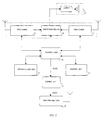
- the following figure 6 shows a timing chart related to the above mentioned sequence of operations.
- the activity intervals of the units involved in the sequence described in the preceding figure 4 and namely the PLL unit, the stereo decoding unit, the data decoding unit, the control unit, the RAM memory, the ROM memory, the data coding unit and the transmitter of the FDC signal are highlighted.
- the PLL unit is activated to lock the requested frequency.
- the search for this frequency is performed, which is locked in the time t2.
- the control unit is activated, which moreover will remain active until the end of the described cycle.
- the stereo decoding unit to audio-reproduce the radio signal and the data decoding unit to decode data coming from the associated RDS signal. Also the stereo decoding unit will remain active until the end of the cycle.
- the data decoding unit is deactivated and the RAM memory is enabled in order to allow writing the decoded data. This writing operation takes place during the interval t3-t4.
- the ROM memory is activated in order to allow reading the PRIC code containing information identifying the transmitter-receiver apparatus. Such PRIC code is stored in the RAM memory during the following time interval t5-t6.
- a check is performed to verify if the DBF function is active or not. Should this function be active, the data related to the DBF signal component DBF are read by the RAM memory during the time interval t6-t7.
- the data coding unit is furthermore activated, which will remain active until the time t8.
- the radio transmitter is activated which provides for transmitting the FDC signal, during the time interval t8-t9.
- the following interval t9-t10 represents the delay cycle inserted to synchronize the following coding operation of the FDC signal.
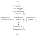
- the following figure 7 shows the block diagram of the receiving, processing, storing and sorting system of the data coming from each of the radio receivers of the so far described type.
- the system represented in the figure is constituted by:
- a second embodiment of this data receiving, processing, storing and sorting system could provide that the reception of the data transmitted by each of the radio receivers takes places according to different modes compared to what has been now described.
- These radio-transmitted data could, for example, be received through a network such as Internet, according to modes similar to what has been provided by some broadcasting stations.
- the data coming from the transmitter-receiver apparatuses are then processed, stored and utilized in order to provide a plurality of services both to the broadcasting stations and to the single radio-listener.
- Such systems allows:
- the hereto described service examples are only some services which can be implemented by means of the present invention. Other and different services could be easily provided and implemented by exploiting the possibility of a two-directional communication between the broadcasting stations, a data-receiving station and a plurality of radio-listeners.
Landscapes
- Engineering & Computer Science (AREA)
- Computer Networks & Wireless Communication (AREA)
- Signal Processing (AREA)
- Circuits Of Receivers In General (AREA)
- Transceivers (AREA)
Applications Claiming Priority (2)
| Application Number | Priority Date | Filing Date | Title |
|---|---|---|---|
| IT2000RM000069A IT1315831B1 (it) | 2000-02-14 | 2000-02-14 | Apparecchio ricetrasmittente con unita di codifica di segnale secondolo standard rds. |
| ITRM200069 | 2000-02-14 |
Publications (2)
| Publication Number | Publication Date |
|---|---|
| EP1126644A2 true EP1126644A2 (de) | 2001-08-22 |
| EP1126644A3 EP1126644A3 (de) | 2006-05-10 |
Family
ID=11454430
Family Applications (1)
| Application Number | Title | Priority Date | Filing Date |
|---|---|---|---|
| EP01830080A Withdrawn EP1126644A3 (de) | 2000-02-14 | 2001-02-09 | Sender-Empfänger mit Signalkodiereinheit nach RDS-Standard |
Country Status (3)
| Country | Link |
|---|---|
| US (1) | US6847802B2 (de) |
| EP (1) | EP1126644A3 (de) |
| IT (1) | IT1315831B1 (de) |
Families Citing this family (5)
| Publication number | Priority date | Publication date | Assignee | Title |
|---|---|---|---|---|
| EP1447928A1 (de) * | 2003-02-13 | 2004-08-18 | Harman/Becker Automotive Systems (Becker Division) GmbH | Empfänger für Fernseh- und/oder Rundfunkprogramme und Verfahren zur Überwachung von Fernseh- und/oder Rundfunkprogrammen |
| EP1475909B1 (de) * | 2003-05-08 | 2011-09-28 | Harman Becker Automotive Systems GmbH | Hintergrundtuner eines Rundfunkempfängers zum Empfangen von Verkehrs- und Reise-Information und zum Untersuchen von alternativen Frequenzen |
| US7231177B2 (en) * | 2003-11-13 | 2007-06-12 | Delphi Technologies, Inc. | Audio system with first and second units having wireless interface, and audio recievers therefor |
| US7970342B1 (en) | 2006-02-06 | 2011-06-28 | Griffin Technology Inc. | Digital music player accessory with digital communication capability |
| US7587167B2 (en) * | 2006-03-08 | 2009-09-08 | Visteon Global Technologies, Inc. | Integrated digital radio module |
Family Cites Families (12)
| Publication number | Priority date | Publication date | Assignee | Title |
|---|---|---|---|---|
| WO1996021284A1 (en) * | 1994-12-29 | 1996-07-11 | Seiko Communications Systems, Inc. | A system for identifying and responding to different broadcast programs |
| CN1089902C (zh) * | 1995-09-01 | 2002-08-28 | 布劳管理有限责任公司 | 运动物体定位系统与接收装置及其处理数据的方法 |
| CN1174638A (zh) * | 1995-10-24 | 1998-02-25 | 菲利浦电子有限公司 | 一种无线电广播系统,在这种系统中使用的发射机和接收机,无线电广播方法和无线电广播信号 |
| DE19626907C2 (de) * | 1996-07-04 | 1998-07-23 | Wolfgang Mintrop | Verfahren und Schaltungsanordnung zum Ermitteln der Einschaltquote bei der Ausstrahlung von Fernsehprogrammen |
| FR2759829B1 (fr) * | 1997-02-18 | 1999-05-07 | Radio Shopper | Assemblage comportant un poste radiophonique a recepteur de donnees numeriques, notamment de type rds |
| IT1297066B1 (it) | 1997-11-18 | 1999-08-03 | Riccardo Migliaccio | Apparecchio e metodo per la ricezione di segnali radio trasmessi tramite sistema rds |
| US6625464B1 (en) * | 1998-08-13 | 2003-09-23 | Data Fm, Incorporated | Codeable programmable receiver and point to multipoint messaging system |
| WO2000036771A1 (de) * | 1998-12-14 | 2000-06-22 | Mannesmann Ag | Duales übertragungssystem |
| US6088577A (en) * | 1999-01-13 | 2000-07-11 | Clariti Telecommunications International, Ltd. | Multiple subcarrier communication system |
| US6493546B2 (en) * | 1999-03-05 | 2002-12-10 | Xm Satellite Radio Inc. | System for providing signals from an auxiliary audio source to a radio receiver using a wireless link |
| US6674993B1 (en) * | 1999-04-30 | 2004-01-06 | Microvision, Inc. | Method and system for identifying data locations associated with real world observations |
| US6563805B1 (en) * | 1999-11-05 | 2003-05-13 | Xm Satellite Radio, Inc. | Digital radio prepaid music recording system |
-
2000
- 2000-02-14 IT IT2000RM000069A patent/IT1315831B1/it active
-
2001
- 2001-01-29 US US09/771,941 patent/US6847802B2/en not_active Expired - Fee Related
- 2001-02-09 EP EP01830080A patent/EP1126644A3/de not_active Withdrawn
Also Published As
| Publication number | Publication date |
|---|---|
| ITRM20000069A0 (it) | 2000-02-14 |
| EP1126644A3 (de) | 2006-05-10 |
| US6847802B2 (en) | 2005-01-25 |
| ITRM20000069A1 (it) | 2001-08-14 |
| US20010043645A1 (en) | 2001-11-22 |
| IT1315831B1 (it) | 2003-03-26 |
Similar Documents
| Publication | Publication Date | Title |
|---|---|---|
| EP0602438A1 (de) | RDS-Rundfunkempfänger | |
| US5278988A (en) | Automated receiver monitoring method and apparatus | |
| WO2008071460A1 (en) | Portable device with combined broadcast and web radio | |
| US7912421B2 (en) | Radio device | |
| JP4388031B2 (ja) | デジタルマルチメディア放送チャネルの管理方法、デジタルマルチメディア放送システム及びデジタルマルチメディア放送を受信可能な端末機 | |
| US7308236B2 (en) | Broadcast receiver and channel scanning method | |
| EP0448618A1 (de) | Modifiziertes rds-funksystem. | |
| KR970705253A (ko) | 공동파 방송 네트워크에서 로컬 무선 프로그램의 전송과 선택을 위한 방법 및 이를 위한 송신기와 수신기(process, sender and receiver for transmitting and selecting local radio programs in a common-wave broadcasting network) | |
| KR100800869B1 (ko) | 지상파 dmb 서비스 방법 및 장치와 시스템 | |
| US6847802B2 (en) | Transmitter-receiver apparatus with signal coding unit according to RDS standard | |
| CN1059060C (zh) | 一种调谐接收机的方法及采用这种方法的接收机 | |
| GB2418803A (en) | Emergency digital broadcast message transmitter system | |
| CN102055541B (zh) | 多路复用广播接收机 | |
| US6912378B2 (en) | Multiple band scanning receiver system having data and speech searching capability | |
| EP1800424A2 (de) | Verfahren und system zum senden von notfall-nachrichten in einer region wie etwa einem tunnel oder eine brücke | |
| JP2885809B2 (ja) | 受信機 | |
| JPH02213229A (ja) | Rdsの自動追従方法 | |
| JP3968541B2 (ja) | デジタルオーディオ放送の受信機 | |
| KR100656080B1 (ko) | 홈 네트워크 상의 방송파 수신 가능한 가전제품 및 그의정보 표시 방법 | |
| KR100744292B1 (ko) | 멀티 다운로드 알고리즘을 사용한 지상파 dmb 데이터다운로드 방법과 그 방법이 적용되는 dmb 데이터다운로드 장치 | |
| KR101577262B1 (ko) | 실시간 수신가능 방송국 목록을 제공하는 dmb 수신 모듈 및 방법 | |
| KR102244965B1 (ko) | 멀티데이터 방송 수신장치 및 그 제어방법 | |
| US7991011B2 (en) | Identification of changes in broadcast database | |
| EP0688112A1 (de) | Verfahren für die Auswahl eines anderen Funkprogramms mit Verkehrsinformationen unter Verwendung von Radiodatenempfängern | |
| JPH01276828A (ja) | Rds受信方法 |
Legal Events
| Date | Code | Title | Description |
|---|---|---|---|
| PUAI | Public reference made under article 153(3) epc to a published international application that has entered the european phase |
Free format text: ORIGINAL CODE: 0009012 |
|
| AK | Designated contracting states |
Kind code of ref document: A2 Designated state(s): AT BE CH CY DE DK ES FI FR GB GR IE IT LI LU MC NL PT SE TR |
|
| AX | Request for extension of the european patent |
Free format text: AL;LT;LV;MK;RO;SI |
|
| RIC1 | Information provided on ipc code assigned before grant |
Ipc: 7H 04H 9/00 B Ipc: 7H 04H 1/00 A |
|
| PUAL | Search report despatched |
Free format text: ORIGINAL CODE: 0009013 |
|
| AK | Designated contracting states |
Kind code of ref document: A3 Designated state(s): AT BE CH CY DE DK ES FI FR GB GR IE IT LI LU MC NL PT SE TR |
|
| AX | Request for extension of the european patent |
Extension state: AL LT LV MK RO SI |
|
| AKX | Designation fees paid | ||
| REG | Reference to a national code |
Ref country code: DE Ref legal event code: 8566 |
|
| 17P | Request for examination filed |
Effective date: 20070129 |
|
| RBV | Designated contracting states (corrected) |
Designated state(s): AT BE CH CY DE DK ES FI FR GB GR IE IT LI LU MC NL PT SE TR |
|
| 17Q | First examination report despatched |
Effective date: 20070618 |
|
| STAA | Information on the status of an ep patent application or granted ep patent |
Free format text: STATUS: THE APPLICATION IS DEEMED TO BE WITHDRAWN |
|
| 18D | Application deemed to be withdrawn |
Effective date: 20071030 |