EP1126645A2 - Réseau de communication à protocole de communication commandé en temps - Google Patents
Réseau de communication à protocole de communication commandé en temps Download PDFInfo
- Publication number
- EP1126645A2 EP1126645A2 EP01200492A EP01200492A EP1126645A2 EP 1126645 A2 EP1126645 A2 EP 1126645A2 EP 01200492 A EP01200492 A EP 01200492A EP 01200492 A EP01200492 A EP 01200492A EP 1126645 A2 EP1126645 A2 EP 1126645A2
- Authority
- EP
- European Patent Office
- Prior art keywords
- divider
- correction term
- clock signal
- arrangement
- synchronization circuit
- Prior art date
- Legal status (The legal status is an assumption and is not a legal conclusion. Google has not performed a legal analysis and makes no representation as to the accuracy of the status listed.)
- Granted
Links
Images




Classifications
-
- H—ELECTRICITY
- H04—ELECTRIC COMMUNICATION TECHNIQUE
- H04L—TRANSMISSION OF DIGITAL INFORMATION, e.g. TELEGRAPHIC COMMUNICATION
- H04L7/00—Arrangements for synchronising receiver with transmitter
- H04L7/02—Speed or phase control by the received code signals, the signals containing no special synchronisation information
- H04L7/033—Speed or phase control by the received code signals, the signals containing no special synchronisation information using the transitions of the received signal to control the phase of the synchronising-signal-generating means, e.g. using a phase-locked loop
- H04L7/0331—Speed or phase control by the received code signals, the signals containing no special synchronisation information using the transitions of the received signal to control the phase of the synchronising-signal-generating means, e.g. using a phase-locked loop with a digital phase-locked loop [PLL] processing binary samples, e.g. add/subtract logic for correction of receiver clock
-
- G—PHYSICS
- G06—COMPUTING OR CALCULATING; COUNTING
- G06F—ELECTRIC DIGITAL DATA PROCESSING
- G06F1/00—Details not covered by groups G06F3/00 - G06F13/00 and G06F21/00
- G06F1/04—Generating or distributing clock signals or signals derived directly therefrom
- G06F1/14—Time supervision arrangements, e.g. real time clock
-
- H—ELECTRICITY
- H04—ELECTRIC COMMUNICATION TECHNIQUE
- H04J—MULTIPLEX COMMUNICATION
- H04J3/00—Time-division multiplex systems
- H04J3/02—Details
- H04J3/06—Synchronising arrangements
- H04J3/0635—Clock or time synchronisation in a network
- H04J3/0685—Clock or time synchronisation in a node; Intranode synchronisation
- H04J3/0694—Synchronisation in a TDMA node, e.g. TTP
Definitions
- TTP Time-Triggered Protocol
- This protocol provides a correction term available for the implementation of the synchronization, which results from the comparison of the theoretical point in time at which a certain message should arrive with the actual reception time. If this correction term is caused by a creeping, continuous deviation (e.g. caused by aging of the clock source), it must be balanced again and again in every synchronization interval.
- the invention has for its object a communication network with dynamic To create synchronization.
- the synchronization circuit contains a divider control, which is used for ver Change at least one divisor factor when the correction term is exceeded by one predetermined first threshold value is provided.
- the idea on which this invention is based is a synchronization circuit which is implemented by a divider control dynamic configuration of the divider factors when exceeded of the correction term generated in the comparison circuit via a predetermined first Threshold causes. This way there is a continuous deviation of the local Clock from the global clock is taken into account by changing the divider factors once, and multiple tracking to compensate for the deviation found the local clock becomes superfluous.
- a correction term is formed in order to change the divisor factors.
- the Control unit At If the correction term is exceeded above the predetermined first threshold value, the Control unit to a divider factor generator contained in the divider control Control signal. The divider factor generator then performs a divider adjustment.
- the correction term not only the first but also a second threshold, the is greater than the first, a calibration of the divider factors in the calibration unit carried out. This makes it possible to also see large deviations from the local one Clock as e.g. occur after breaks in operation of parts of the communication system can correct permanently.
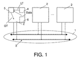
- FIG. 1 An exemplary embodiment of the communication network 1 according to the invention is shown in FIG. 1 shown.
- This communication network 1 can e.g. one from the magazine “Electronics", No. 14, 1999, pages 36 to 43 (Dr. Stefan Polenda, Georg Kroiss: "TTP: “Drive by Wire” within reach ”) known TTP protocol and exists from several network nodes 2, their access to a common communication medium 3, is regulated by a TDMA procedure (Time Division Multiple Access).
- the method ensures that only one network node 2 is connected to a predetermined one Time to send a message.
- a time-controlled protocol like the TTP protocol uses a local clock LT in each network node 2, which is used in a clock generator 4 of the network node 2 is generated.
- the local clock LT becomes too with other nodes a global match, a global clock GT, in a synchronization circuit 5 synchronized.
- a decoder 6 supplies the clock generator for synchronization 4, the synchronization circuit 5 for the node from the communication medium 3 specific dates.
- the synchronization circuit 5 is described in more detail in FIG. 2. She gets the local one Clock LT and a correction term KT to in a divider control 7 and a divider arrangement 8 to modify the local clock signal LT with a prescaler arrangement 9 and thereby delay or advance the next pulse for the global clock GT.
- the correction term KT arises in a comparison circuit 10 and results from the Comparison of the theoretical point in time at which a certain message (data) arrives should, with the actual time of receipt of this message (data) (see journal "Electronics", No. 14, 1999, pages 36 to 43, Dr. Stefan Polenda, Georg Kroiss: "TTP:” Drive by Wire "within reach”).
- Fig. 3 shows an embodiment of the divider control 7 and the divider arrangement 8.
- Die Divider control 7 contains a circuit for threshold value formation 11, the input of which the comparison circuit 10 and its output are connected to a control unit 12.
- the control unit 12 can send control signals to a divider factor generator 13, a calibration unit 14 or a modification device 15 send.
- the divider factor generator 13 and the calibration unit 14 is the comparison circuit of the Correction term KT and the divider arrangement 9 supplied two divider factors.
- Both the divider factor generator 13 and the calibration unit 14 can store data send to the prescaler arrangement 9. This is located together with the modification device 15 and a counter arrangement 16 in the divider arrangement 8 and sends the current divider factors to the counter arrangement 16, which are not only the global ones Clock GT provides, but also a control signal for modification to the Modification device 15 provides. This has a connection to the comparison circuit 10 and the clock generator 4 of the network node. The output of the modification device 15 leads to the counter arrangement 16.
- the control unit 12 sends in circuit for threshold value formation 11 Control signal to the modification device 15.
- the modification device 15 finds a modification of the local clock LT depending on the correction term KT instead of.
- An auxiliary signal HS resulting from the modification device 15 is indicated by divided down a counter array 16.
- Exceeds the determined correction term KT the predetermined first threshold value then the control unit 12 sends a control signal a divider factor generator 13, which changes the divider factors in a prescaler arrangement 9 depending on the correction term KT. If this correction term also exceeds a second threshold value that is greater than the first the control unit 12 sends a control signal to the calibration unit 14.
- the calibration unit 14 determines new values of the divisor factors depending on the correction term KT for the prescaler arrangement 9.
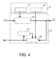
- the prescaler arrangement 9 shown in FIG. 4 has an integer prescaler factor 17 and additionally a non-integer prescaler factor 18.
- a method for handling non-integer prescaler factors is from the publication "A Synchronization Strategy for a time-triggered Multicluster Real-Time system "(Hermann Kopetz, Andreas Krüger, Dietmar Millinger, Anton Schedl, Proc. of the 14 th IEEE Symposium on Reliable Distributed Systems, Bad Neuenahr, Germany, IEEE Press, September 1995) known .
- a counter 19, an adder 20 and an accumulator register 21 form the counter arrangement 16.
- the output of the integer prescaler factor 17 leads to the counter 19 and the output of the non-integer prescaler factor 18 to the adder 20.
- the adder 20 not only sends its data to the modification device 15 but also to an accumulator register 21, which in turn transmits its result to the adder 20. Together, the adder 20 and the accumulator register 21 form an accumulator.
- the counter 19 is initialized with the value of the integer prescaler factor. This counter 19 reduces its content when a pulse of the auxiliary signal HS is received from the modification device 15. When the counter has reached zero, it generates the global clock GT.
- the non-integer prescaler is summed in the accumulator register 21 by the adder 20 until its sum reaches the overflow value (value 1).
- the adder 20 signals the modification device 15 to suppress a pulse of the local clock LT. In this way, the clocking of the counter 19 and thus also of the global clock GT is delayed.
- FIG. 5 shows the local clock LT, the modified auxiliary signal HS and the global clock GT.
- This illustration illustrates the dependency between the global clock GT and the local clock LT of a network node.
- the influence of the divisor factors is shown here using an example configuration.
- the integer prescaler was chosen to be 8, with the non-integer prescaler set to 1/3. Every third period of a global clock is extended by one clock period of a local clock. For this purpose, a pulse is hidden from the local clock at the appropriate time.
- the modified auxiliary signal HS serves as a counter clock to generate the global clock GT. 6 and FIG.
- FIG. 7 show, by way of example for a given local clock LT, the global clock signal GT1 generated in a conventional synchronization with auxiliary signal HS1 and the global clock signal GT2 generated with the aid of the dynamic configuration of the divider factors with auxiliary signal HS2.
- FIG. 6 describes the case of clock acceleration
- FIG. 7 shows the case of clock deceleration.
- the identity of the global clocks GT1 and GT2 can be clearly seen in both cases, while the auxiliary signals on the one hand represent the correction according to the conventional method (HS1) and the inventive dynamic divider factor correction (HS2).
Landscapes
- Engineering & Computer Science (AREA)
- Theoretical Computer Science (AREA)
- Computer Networks & Wireless Communication (AREA)
- Signal Processing (AREA)
- Physics & Mathematics (AREA)
- General Engineering & Computer Science (AREA)
- General Physics & Mathematics (AREA)
- Synchronisation In Digital Transmission Systems (AREA)
- Electric Clocks (AREA)
Applications Claiming Priority (2)
| Application Number | Priority Date | Filing Date | Title |
|---|---|---|---|
| DE10007070 | 2000-02-16 | ||
| DE10007070A DE10007070A1 (de) | 2000-02-16 | 2000-02-16 | Kommunikationsnetzwerk mit zeitgesteuertem Kommunikationsprotokoll |
Publications (3)
| Publication Number | Publication Date |
|---|---|
| EP1126645A2 true EP1126645A2 (fr) | 2001-08-22 |
| EP1126645A3 EP1126645A3 (fr) | 2005-09-14 |
| EP1126645B1 EP1126645B1 (fr) | 2008-07-09 |
Family
ID=7631205
Family Applications (1)
| Application Number | Title | Priority Date | Filing Date |
|---|---|---|---|
| EP01200492A Expired - Lifetime EP1126645B1 (fr) | 2000-02-16 | 2001-02-09 | Réseau de communication à protocole de communication commandé en temps |
Country Status (4)
| Country | Link |
|---|---|
| US (1) | US6917656B2 (fr) |
| EP (1) | EP1126645B1 (fr) |
| JP (1) | JP2001251282A (fr) |
| DE (2) | DE10007070A1 (fr) |
Families Citing this family (5)
| Publication number | Priority date | Publication date | Assignee | Title |
|---|---|---|---|---|
| DE10147422A1 (de) * | 2001-09-26 | 2003-04-24 | Siemens Ag | Kommunikationssystem und Verfahren zur Synchronisation eines Kommunikationszyklus |
| EP1335520B1 (fr) * | 2002-02-11 | 2018-05-30 | Semiconductor Components Industries, LLC | Système de bus multiplexé avec correction du rapport cyclique |
| DE10347381B4 (de) | 2003-10-08 | 2019-05-09 | Volkswagen Ag | Verfahren und Vorrichtung zur fehlerabgesicherten Übertragung von Nutzdaten |
| US7424076B2 (en) * | 2004-01-22 | 2008-09-09 | Nokia Corporation | System and method for providing synchronization information to a receiver |
| DE102004006398B4 (de) * | 2004-02-10 | 2006-06-08 | Atmel Germany Gmbh | Verfahren und Vorrichtung zum Synchronisieren einer Funktionseinheit auf eine vorgegebene Taktfrequenz |
Family Cites Families (4)
| Publication number | Priority date | Publication date | Assignee | Title |
|---|---|---|---|---|
| US4939753A (en) * | 1989-02-24 | 1990-07-03 | Rosemount Inc. | Time synchronization of control networks |
| EP0718995A1 (fr) * | 1994-12-20 | 1996-06-26 | International Business Machines Corporation | Appareil et méthode pour synchroniser des signaux d'horloge pour des liaisons numériques |
| AU8684098A (en) * | 1997-07-31 | 1999-02-22 | Sapphire Communications, Inc. | Means and method for a synchronous network communications system |
| DE19849458A1 (de) * | 1998-10-28 | 2000-05-04 | Philips Corp Intellectual Pty | Drahtloses Netzwerk mit einer Taktsynchronisation |
-
2000
- 2000-02-16 DE DE10007070A patent/DE10007070A1/de not_active Withdrawn
-
2001
- 2001-02-09 EP EP01200492A patent/EP1126645B1/fr not_active Expired - Lifetime
- 2001-02-09 DE DE50114081T patent/DE50114081D1/de not_active Expired - Lifetime
- 2001-02-12 US US09/781,504 patent/US6917656B2/en not_active Expired - Lifetime
- 2001-02-13 JP JP2001035631A patent/JP2001251282A/ja not_active Withdrawn
Non-Patent Citations (2)
| Title |
|---|
| KOPETZ H ET AL: "A Synchronization Strategy for Time-Triggered Multicluster Real-Time System" RELIABLE DISTRIBUTED SYSTEMS. BAD NEUENAHR, SEPT. 13 - 15, 1995, NEW YORK, IEEE, US, 13. September 1995 (1995-09-13), Seiten 154-161, XP002293492 * |
| POLEDNA S ET AL: "TTP: DRIVE BY WIRE IN GREIFBARER NAEHE ECHTZEIT-KOMMUNIKATION IM AUTOMOBIL MIT ZEITGESTEUERTEM PROTOKOLL ERLAUBT HOCHZUVERLAESSIGE ANWENDUNGEN" ELEKTRONIK, WEKA FACHZEITSCR.-VERLAG, MUNCHEN, DE, Bd. 48, Nr. 14, 13. Juli 1999 (1999-07-13), Seite 36-38,40,42,43, XP000913186 ISSN: 0013-5658 * |
Also Published As
| Publication number | Publication date |
|---|---|
| EP1126645B1 (fr) | 2008-07-09 |
| JP2001251282A (ja) | 2001-09-14 |
| EP1126645A3 (fr) | 2005-09-14 |
| DE50114081D1 (de) | 2008-08-21 |
| US6917656B2 (en) | 2005-07-12 |
| US20020052707A1 (en) | 2002-05-02 |
| DE10007070A1 (de) | 2001-08-30 |
Similar Documents
| Publication | Publication Date | Title |
|---|---|---|
| DE3244327C2 (de) | Schaltung zum Erzeugen einer Substrat-Vorspannung | |
| DE10320794B3 (de) | Vorrichtung und Verfahren zur Korrektur des Tastverhältnisses eines Taktsignals | |
| DE4342266A1 (de) | Taktgenerator sowie Phasenkomparator zur Verwendung in einem solchen Taktgenerator | |
| DE2216123A1 (de) | Verfahren und Anordnung zur Analog Digital Umsetzung unter mehrfacher Inte gration | |
| DE3212453C2 (fr) | ||
| DE2751021A1 (de) | Anordnung zum synchronisieren von oszillatorsignalen | |
| DE2648560C2 (de) | Synchronisierung von Taktsignalen mit Eingangssignalen | |
| EP0023331B1 (fr) | Circuit pour la synchronisation d'un dispositif subordonné, en particulier un poste d'abonné numérique par un dispositif d'ordre supérieur, en particulier un central de communication numérique d'un réseau de télécommunication MIC | |
| DE2119091A1 (de) | Spannungsgesteuerter Taktgenerator | |
| DE3416548A1 (de) | Verfahren und einrichtung zur optimalen zeitlichen einstellung von taktsignalen fuer digitalrechner | |
| EP1126645B1 (fr) | Réseau de communication à protocole de communication commandé en temps | |
| DE3315372C2 (fr) | ||
| DE69106422T2 (de) | Multiplexierungsanordnung für Taktsignale. | |
| DE2658908B2 (de) | Elektronische Uhr | |
| EP0128396A1 (fr) | Système de communication intégré à bus | |
| DE3920391A1 (de) | Schaltungsanordnung zur anpassung der bitraten zweier signale | |
| EP0180001A2 (fr) | Circuit de mise en mémoire temporaire de signaux numériques | |
| DE3743434A1 (de) | Zeitsignalgeber | |
| EP0237699B1 (fr) | Méthode et montage de circuit pour la synchronisation d'un oscillateur commandé en tension appartenant à un central téléphonique | |
| DE1256689C2 (de) | Taktgeber mit einer einrichtung zur abschaltung und zur phasenrichtigen wiedereinschaltung der taktsignale von elektronischen datenverarbeitenden anlagen | |
| DE19739245C2 (de) | Digitale Schaltung mit einer Filtereinheit zur Unterdrückung von Störimpulsen | |
| DE2840853A1 (de) | Datenimpulsempfangsanordnung | |
| DE10056164C1 (de) | Schaltungsanordnung zur Erzeugung von mit Ausgangssignalen eines Taktgenerators flankensynchronen Taktsignalen für einen Halbleiterspeicher | |
| DE2058958C3 (de) | Schaltung zur Verringerung des Einflusses von Störimpulsen auf Korrekrurimpulse, die die Synchronisation von Daten- mit Taktimpulsen bewirken | |
| EP0053650B1 (fr) | Circuit intégré monolithique de balayage vertical des récepteurs de télévision à traitement de signal corrigé digitalement en tangente à la fréquence de ligne |
Legal Events
| Date | Code | Title | Description |
|---|---|---|---|
| PUAI | Public reference made under article 153(3) epc to a published international application that has entered the european phase |
Free format text: ORIGINAL CODE: 0009012 |
|
| AK | Designated contracting states |
Kind code of ref document: A2 Designated state(s): AT BE CH CY DE DK ES FI FR GB GR IE IT LI LU MC NL PT SE TR |
|
| AX | Request for extension of the european patent |
Free format text: AL;LT;LV;MK;RO;SI |
|
| RAP1 | Party data changed (applicant data changed or rights of an application transferred) |
Owner name: PHILIPS CORPORATE INTELLECTUAL PROPERTY GMBH Owner name: KONINKLIJKE PHILIPS ELECTRONICS N.V. |
|
| RAP1 | Party data changed (applicant data changed or rights of an application transferred) |
Owner name: PHILIPS INTELLECTUAL PROPERTY & STANDARDS GMBH Owner name: KONINKLIJKE PHILIPS ELECTRONICS N.V. |
|
| PUAL | Search report despatched |
Free format text: ORIGINAL CODE: 0009013 |
|
| AK | Designated contracting states |
Kind code of ref document: A3 Designated state(s): AT BE CH CY DE DK ES FI FR GB GR IE IT LI LU MC NL PT SE TR |
|
| AX | Request for extension of the european patent |
Extension state: AL LT LV MK RO SI |
|
| RAP1 | Party data changed (applicant data changed or rights of an application transferred) |
Owner name: KONINKLIJKE PHILIPS ELECTRONICS N.V. Owner name: PHILIPS INTELLECTUAL PROPERTY & STANDARDS GMBH |
|
| 17P | Request for examination filed |
Effective date: 20060314 |
|
| AKX | Designation fees paid |
Designated state(s): DE FR GB |
|
| RAP1 | Party data changed (applicant data changed or rights of an application transferred) |
Owner name: NXP B.V. |
|
| 17Q | First examination report despatched |
Effective date: 20071002 |
|
| GRAP | Despatch of communication of intention to grant a patent |
Free format text: ORIGINAL CODE: EPIDOSNIGR1 |
|
| GRAS | Grant fee paid |
Free format text: ORIGINAL CODE: EPIDOSNIGR3 |
|
| GRAA | (expected) grant |
Free format text: ORIGINAL CODE: 0009210 |
|
| AK | Designated contracting states |
Kind code of ref document: B1 Designated state(s): DE FR GB |
|
| REG | Reference to a national code |
Ref country code: GB Ref legal event code: FG4D Free format text: NOT ENGLISH |
|
| REF | Corresponds to: |
Ref document number: 50114081 Country of ref document: DE Date of ref document: 20080821 Kind code of ref document: P |
|
| PLBE | No opposition filed within time limit |
Free format text: ORIGINAL CODE: 0009261 |
|
| STAA | Information on the status of an ep patent application or granted ep patent |
Free format text: STATUS: NO OPPOSITION FILED WITHIN TIME LIMIT |
|
| 26N | No opposition filed |
Effective date: 20090414 |
|
| PGFP | Annual fee paid to national office [announced via postgrant information from national office to epo] |
Ref country code: DE Payment date: 20100219 Year of fee payment: 10 |
|
| REG | Reference to a national code |
Ref country code: DE Ref legal event code: R119 Ref document number: 50114081 Country of ref document: DE Effective date: 20110901 |
|
| PG25 | Lapsed in a contracting state [announced via postgrant information from national office to epo] |
Ref country code: DE Free format text: LAPSE BECAUSE OF NON-PAYMENT OF DUE FEES Effective date: 20110901 |
|
| REG | Reference to a national code |
Ref country code: FR Ref legal event code: PLFP Year of fee payment: 16 |
|
| REG | Reference to a national code |
Ref country code: FR Ref legal event code: PLFP Year of fee payment: 17 |
|
| REG | Reference to a national code |
Ref country code: FR Ref legal event code: PLFP Year of fee payment: 18 |
|
| PGFP | Annual fee paid to national office [announced via postgrant information from national office to epo] |
Ref country code: GB Payment date: 20200123 Year of fee payment: 20 |
|
| PGFP | Annual fee paid to national office [announced via postgrant information from national office to epo] |
Ref country code: FR Payment date: 20200122 Year of fee payment: 20 |
|
| REG | Reference to a national code |
Ref country code: GB Ref legal event code: PE20 Expiry date: 20210208 |
|
| PG25 | Lapsed in a contracting state [announced via postgrant information from national office to epo] |
Ref country code: GB Free format text: LAPSE BECAUSE OF EXPIRATION OF PROTECTION Effective date: 20210208 |