EP1126740B1 - Procédé et système de routage optique de paquets de longueur variable - Google Patents
Procédé et système de routage optique de paquets de longueur variable Download PDFInfo
- Publication number
- EP1126740B1 EP1126740B1 EP01301171A EP01301171A EP1126740B1 EP 1126740 B1 EP1126740 B1 EP 1126740B1 EP 01301171 A EP01301171 A EP 01301171A EP 01301171 A EP01301171 A EP 01301171A EP 1126740 B1 EP1126740 B1 EP 1126740B1
- Authority
- EP
- European Patent Office
- Prior art keywords
- label
- frame
- block
- payload
- optical
- Prior art date
- Legal status (The legal status is an assumption and is not a legal conclusion. Google has not performed a legal analysis and makes no representation as to the accuracy of the status listed.)
- Expired - Lifetime
Links
- 230000003287 optical effect Effects 0.000 title claims description 155
- 238000000034 method Methods 0.000 title claims description 26
- 230000005540 biological transmission Effects 0.000 claims description 12
- 230000003139 buffering effect Effects 0.000 claims description 6
- 230000003111 delayed effect Effects 0.000 claims description 6
- 239000000835 fiber Substances 0.000 description 11
- 238000010586 diagram Methods 0.000 description 8
- 238000006243 chemical reaction Methods 0.000 description 4
- 239000013307 optical fiber Substances 0.000 description 4
- 238000010276 construction Methods 0.000 description 2
- 230000007812 deficiency Effects 0.000 description 1
- 230000001934 delay Effects 0.000 description 1
- 230000001066 destructive effect Effects 0.000 description 1
- 230000000694 effects Effects 0.000 description 1
- 239000000284 extract Substances 0.000 description 1
- 238000004321 preservation Methods 0.000 description 1
- 230000001172 regenerating effect Effects 0.000 description 1
Images


Classifications
-
- H—ELECTRICITY
- H04—ELECTRIC COMMUNICATION TECHNIQUE
- H04Q—SELECTING
- H04Q11/00—Selecting arrangements for multiplex systems
- H04Q11/0001—Selecting arrangements for multiplex systems using optical switching
- H04Q11/0062—Network aspects
- H04Q11/0066—Provisions for optical burst or packet networks
-
- H—ELECTRICITY
- H04—ELECTRIC COMMUNICATION TECHNIQUE
- H04L—TRANSMISSION OF DIGITAL INFORMATION, e.g. TELEGRAPHIC COMMUNICATION
- H04L49/00—Packet switching elements
- H04L49/25—Routing or path finding in a switch fabric
-
- H—ELECTRICITY
- H04—ELECTRIC COMMUNICATION TECHNIQUE
- H04Q—SELECTING
- H04Q11/00—Selecting arrangements for multiplex systems
- H04Q11/0001—Selecting arrangements for multiplex systems using optical switching
- H04Q11/0005—Switch and router aspects
-
- H—ELECTRICITY
- H04—ELECTRIC COMMUNICATION TECHNIQUE
- H04L—TRANSMISSION OF DIGITAL INFORMATION, e.g. TELEGRAPHIC COMMUNICATION
- H04L49/00—Packet switching elements
- H04L49/25—Routing or path finding in a switch fabric
- H04L49/253—Routing or path finding in a switch fabric using establishment or release of connections between ports
- H04L49/254—Centralised controller, i.e. arbitration or scheduling
-
- H—ELECTRICITY
- H04—ELECTRIC COMMUNICATION TECHNIQUE
- H04L—TRANSMISSION OF DIGITAL INFORMATION, e.g. TELEGRAPHIC COMMUNICATION
- H04L49/00—Packet switching elements
- H04L49/35—Switches specially adapted for specific applications
- H04L49/356—Switches specially adapted for specific applications for storage area networks
- H04L49/357—Fibre channel switches
-
- H—ELECTRICITY
- H04—ELECTRIC COMMUNICATION TECHNIQUE
- H04Q—SELECTING
- H04Q11/00—Selecting arrangements for multiplex systems
- H04Q11/0001—Selecting arrangements for multiplex systems using optical switching
- H04Q11/0005—Switch and router aspects
- H04Q2011/0007—Construction
- H04Q2011/0035—Construction using miscellaneous components, e.g. circulator, polarisation, acousto/thermo optical
-
- H—ELECTRICITY
- H04—ELECTRIC COMMUNICATION TECHNIQUE
- H04Q—SELECTING
- H04Q11/00—Selecting arrangements for multiplex systems
- H04Q11/0001—Selecting arrangements for multiplex systems using optical switching
- H04Q11/0005—Switch and router aspects
- H04Q2011/0037—Operation
- H04Q2011/0039—Electrical control
-
- H—ELECTRICITY
- H04—ELECTRIC COMMUNICATION TECHNIQUE
- H04Q—SELECTING
- H04Q11/00—Selecting arrangements for multiplex systems
- H04Q11/0001—Selecting arrangements for multiplex systems using optical switching
- H04Q11/0005—Switch and router aspects
- H04Q2011/0037—Operation
- H04Q2011/0047—Broadcast; Multicast
-
- H—ELECTRICITY
- H04—ELECTRIC COMMUNICATION TECHNIQUE
- H04Q—SELECTING
- H04Q11/00—Selecting arrangements for multiplex systems
- H04Q11/0001—Selecting arrangements for multiplex systems using optical switching
- H04Q11/0062—Network aspects
- H04Q2011/0069—Network aspects using dedicated optical channels
-
- H—ELECTRICITY
- H04—ELECTRIC COMMUNICATION TECHNIQUE
- H04Q—SELECTING
- H04Q11/00—Selecting arrangements for multiplex systems
- H04Q11/0001—Selecting arrangements for multiplex systems using optical switching
- H04Q11/0062—Network aspects
- H04Q2011/0077—Labelling aspects, e.g. multiprotocol label switching [MPLS], G-MPLS, MPAS
Definitions
- the present invention relates to optical communications networks, and in particular to a method and system for optical routing of variable length packet data across an optical communications network.
- IP internet protocol
- IP packets are converted into optical form and launched into a fiber optic link towards a node of the network.
- the optical signal arrives at the node, it is usually converted back into electronic form and buffered to allow the header portion of the IP packet to be extracted and decoded to determine the routing for the next hop towards the destination.
- the header portion is transmitted over a link on one wavelength (or channel) and the data portion of the packet is transmitted on a second wavelength. Accordingly, at each node it is only necessary to electronically decode the header portion of the packet, which can be easily detected independently of the data portion of the packet.
- the decoded header portion can then be used to determine packet routing in a conventional manner, and this routing information is used to control a transparent optical switch to guide the data portion of the packet through the transparent optical switch and into a downstream link without being converted into an electronic signal and back again to an optical signal.
- Optical buffering of the data portion of the packet e.g. by use of one or more fiber rings having a predetermined length) is used to ensure proper timing between the header and data portions of each packet, and may also be used to resolve contention issues and provide add/drop functionality of the node.
- Known methods of buffering (or delaying) optical signals rely on the use of optical fiber rings or the like having a predetermined length. An optical signal can therefore be delayed for a period of time by launching the signal into the fiber ring. According to Boncek, such a ring is used on the input side of each node to delay the data portion of the packet for a period of time sufficient to allow the header portion to be decoded and the transparent optical switch set to provide routing of the data portion through to the appropriate output node.
- the delay loop on the input side of the node can also be adjusted to compensate for known differences in the propagation speed of the header and data portions of the packet through the link.
- a further delay ring can also be used within the transparent optical switch to resolve contention issues by enabling a data portion of a packet to be delayed by a period of time equivalent to the length of a data packet arriving on another input node, to thereby enable that other data packet to clear an output port before the first data packet arrives at that same output port.
- the use of a fiber ring for delaying and buffering optical signals suffers the disadvantage that the amount of delay is governed primarily by the length of the fiber ring (the time delay is equal to the length of the ring divided by the speed of light in the fiber medium of the ring). This is generally fixed during the design and construction of the fiber ring, and cannot be varied during operation of the node. Because contention resolution requires one data packet to be delayed by a period of time equal to or greater than the length of a second data packet, assumptions must be made concerning the maximum allowable packet length during the design phase of the node. Successful operation of the network depends on the data packets never being longer than the previously defined maximum allowable length.
- the defined maximum length is too large, unnecessarily long delays will be incurred as packets move through the node.
- the defined maximum length is too small, the available band-width of the network may be unnecessarily limited.
- Boncek's use of delay rings at the input of the network node imposes a further restriction that the size and content of the packet header must also be predetermined at the time of design and construction of the node, because the header portion must be fully decoded and interpreted before the delayed data portion arrives at the transparent optical switch.
- the transparent optical node structure of Boncek will only work in a network environment in which data packets of a uniform predefined size and format are employed.
- IP multi protocol label switching
- an object of the present invention is to provide a method and system enabling full optical routing of variable length packetized data across an optical communications network.
- Another object of the present invention is to provide an optical communications system in which variable length packetized data is optically routed across the communications system within fixed length data frames.
- a still further object of the present invention is to provide an optical communications system in which variable length data packets are optically routed across the communications system on the basis of routing information encoded within a label block which is independent of the format of the variable length data packet.
- an aspect of the present invention provides a method of routing variable-length packet data as set out in claim 1 appended hereto.
- Another aspect of the present invention provides a communications network as set out in claim 21 appended hereto.
- a further aspect of the present invention provides a router as set out in claim 37 appended hereto.
- the communications network may be a wave division multiplex (WDM) optical network.
- WDM wave division multiplex
- the communications network is adapted for multi-protocol label switched (MPLS) routing of the packet data traffic.
- MPLS multi-protocol label switched
- the packet data traffic may include any one or more of internet protocol (IP) packets having a variable length, and asynchronous transfer mode (ATM) frames.
- IP internet protocol
- ATM asynchronous transfer mode
- a number N of payload blocks, and the predetermined length of each payload block of each frame can be selected based on an expected mean length of the data packets, or may be selected based on other criteria.
- inverse-multiplexing a data packet preferably includes dividing the data packet into N packet segments of substantially equal length. When the length of each packet segment is less than or equal to the length of each payload block, each packet segment can be buffered for transmission within a respective payload block of a frame.
- each packet segment when the length of each packet segment is greater than the length of each payload block, each packet segment may be subdivided into two or more portions, each portion having a length equal to or less than the length of a payload block. Each portion may then be buffered for transmission within a respective payload block of respective successive frames.
- a large data packet can be subdivided into two or more portions and transmitted within a corresponding number of frames.
- the length of each portion may be the same, or may differ.
- the label block of each frame preferably comprises encoded information concerning at least a start time and routing across the network of the frame.
- the start time may be indicative of a delay period between an arrival time of the label block and an arrival time of the payload blocks of a frame.
- the start time may also be indicative of a delay period between transmission of the label block of a frame, and subsequent transmission of the payload blocks of the frame.
- the delay period is selected such that the step of establishing a transparent optical path between the input port and the selected output port is completed prior to arrival of the payload blocks of the frame at the input port of the router. This allows the router to set-up the path between the input and output ports prior to arrival of the payload blocks, which can therefore be guided through the router without buffering.
- the label block may also include an end time indicative of the location of the last bit of the data packet within the payload blocks.
- an end time indicative of the location of the last bit of the data packet within the payload blocks.
- the router may include a label regenerator for regenerating the label block of the frame, and an optical coupler for transmitting the regenerated label block over the label channel through the selected output port. Additionally, the router may include means for delaying the payload blocks of the frame for a predetermined period of time during passage of the payload blocks through the router between the input and output ports. The predetermined period is preferably selected to preserve the start time encoded in the label block as the frame passes through the router. By this means, successive routers can be used for end-to-end transport of the frame across the network.
- An advantage of the present invention is that it facilitates full optical routing of IP packets, which naturally vary widely in length, using optical routing equipment designed to accommodate fixed-length data packets.
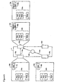
- an optical network 2 usable in conjunction with the present invention generally comprises a plurality of optical routers 4 (four are shown in Fig. 1 ) interconnected by fiber optic links 6.
- Communications devices 8 for example end user personal computers (PCs) or local area network (LAN) servers may be connected to the optical network 2 via one or more access points 10.
- the optical network 2 may also be connected to one or more federated networks 12, for example an ATM or an IP network, through a respective gateway 14.
- each of the optical routers 4 is configured for wave division multiplex (WDM) and/or dense wave division multiplex (DWDM) transport of packet data traffic as will be described in greater detail below.
- WDM wave division multiplex
- DWDM dense wave division multiplex
- packetized data is transported across the optical network 2 within a frame 16 comprising a label block 18 and two or more payload blocks 20.
- Each block (18,20) of the frame 16 is transported across the network 2 on a respective channel (wavelength).
- the label block 18 is transported on a respective label channel
- each payload block 20 is transported on a respective payload channel.
- each of the label and payload channels are predetermined, and remain constant across the optical network 2, so that end-to-end transport of each of the blocks 18,20 is effected without requiring wavelength conversions.
- the label block 18 comprises encoded information concerning the routing of the frame 16 across the network 2 and a start time (TS) of the payload blocks 20 of the frame 16. Encoded information of an end time TE may also be included in the label block 18.
- the routing information may, for example, be an address on the optical network 2 of an access point 10 serving an end-user communications device 8, or a gateway 14 connecting the optical network 2 to an adjacent federated network 12.
- the encoded start time (TS) is used to provide an indication of the length of a time delay (D) between the label block 18 and the payload blocks 20 of the frame 16. There are a variety of ways in which the delay period (D) may be determined.
- TS start time
- D delay between transmission of the first bit of the label block 18 and transmission of the first bit of the payload blocks 20, as shown in Fig. 2a .
- D a predetermined delay between transmission of the first bit of the label block 18 and transmission of the first bit of the payload blocks 20, as shown in Fig. 2a .
- D a predetermined delay between transmission of the first bit of the label block 18 and transmission of the first bit of the payload blocks 20, as shown in Fig. 2a .
- frame spread can be controlled such that all of the payload blocks 20 tend to lag behind the label block 18 as shown in Fig. 2b .
- the start time (TS) encoded in the label block 18 will indicate a minimum delay period (D min ) between arrival of the first bit of the label block 18 and the arrival of the first bit of the first (i.e. the fastest) payload block 20a.
- the start time (TS) can be determined in other ways based on the selection of the channel wavelengths for each of the label and payload channels and the propagation speeds of optical signals at those wavelengths. Other factors may also influence the selection of the start time (TS) and the delay period (D).
- the start time (TS) is selected such that at each optical router 4, the label block 18 arrives at the optical router 4 a period of time prior to the payload blocks 20 sufficient to enable the label block 16 to be decoded and the optical router 4 configured (as will be described in greater detail below) for routing of the payload blocks 20 prior to arrival of the first bit of the payload blocks 20 at the optical router 4.
- the end time TE is used to provide an indication of the location of the last data bit within the payload blocks 20, and may, for example, take the form of a bit count of the data packet.
- the end time TE is of particular use in cases where the size of a data packet is less than the data capacity of the payload blocks 20. In such cases, the payload blocks 20 are only partially filed with "live" data, and the remaining portion of the payload blocks 20 remains unused. In order to maintain system synchronization across the optical network 2, it may be preferable to fill the unused portion of the data blocks 20 with predetermined stuff bits (for example, a clock signal) rather than leave it empty. However, when the original data packet is to be extracted from the frame 16, it becomes necessary to separate the live data from the stuff bits. This can readily be accomplished by means of the end time TE encoded in the label block 18, as will be described in greater detail below.
- each of the payload blocks 20 is transmitted on its own respective payload channel (wavelength), which is different from the label channel used for transmission of the label block 18.
- each of the N (where N is a predetermined number, and is at least 2) payload blocks 20 has a fixed predetermined length.
- the length of a data block 20 may conveniently be defined in terms of time (or equivalently, distance) which is advantageous for resolving issues related to buffering and/or delaying payload blocks 20.
- the data capacity of each payload block 20 (and thus of the frame 16 as a whole) will then be defined as the bit rate multiplied by the payload block length.
- the number and length of the payload blocks 20 may be selected in accordance with various criteria including, for example, an expected mean size of data packets to be transported across the optical network 2. Selection of a suitable combination of the number N of payload blocks 20 and the length of the payload blocks 20 can yield a highly versatile data transport frame 16 which minimizes the amount of wasted (i.e. unused) frame capacity incurred during the transport of live data.
- IP internet protocol
- a frame 16 may, for example, be configured to transport 512 bytes within the payload blocks 20.
- an IP packet conveying information of a mouse button click would be transported within a frame 16 in which the payload blocks are mostly empty, or may contain stuff bits (e.g. a clock signal).
- an IF packet conveying information of a video image may be transported across the optical network 2 within several successive frames 16 each containing closely similar label information. The operation of the invention in both of these cases will be described in greater detail below. In either case, for any given data capacity of a frame 16 it is possible to select between a large number N of short payload blocks 20 and a small number N of long payload blocks 20.
- the use of short data blocks 20 has an advantage in that the data blocks 20 of the frame 16 can be processed through an optical router 4 in a comparatively short period of time, thereby reducing the probability of contention issues arising from two or more frames 16 arriving at respective input ports of the optical router 4 and destined to be routed over the same outbound link for their next hop.
- the use of a large number N of payload blocks may be limited by the number of channels available for packetized data traffic, either due to physical limitations of network equipment, or due to the need to provide a minimum number of channels for connection oriented traffic through the optical network 2.
- Fig. 3 is a block diagram showing principal elements of an interface unit 22 which may be used in a gateway 14 or access point 12 to the optical network 2 to provide conversion between conventional data packet (e.g. IP or ATM) formats and the frames 16 used for transport across the optical network.
- the data packets are transported across a federated network 12 and/or used by end user communications devices 8 as serial signals.
- the interface unit 22 illustrated in Fig. 3 generally comprises a serial-to-parallel converter 24 which converts the serial bit stream of a data packet into N parallel data segments.
- a buffer 26 is connected to the serial-to-parallel converter 24 and is used to store each of the N data segments.
- a set of N optical couplers 28 are connected to the buffer 26 so that the data segments stored within the buffer can be converted into an optical signal having a respective unique wavelength and launched into an optical fiber link 6.
- An additional optical coupler 30 is provided for converting a frame label provided by a label generator 32 into an optical signal that is also launched into the optical fiber link 6.
- a controller unit 34 is used to control operation of the buffer 26, the label generator 32 and the optical couplers 28,30.
- a data packet is received as a serial bit stream and supplied to the controller unit 34 and the serial-to-parallel converter 24.
- the serial-to-parallel converter 24 converts the serial bit stream of the data packet into N parallel bit streams which are stored in the buffer unit as data segments of the data packet.
- the controller unit 34 extracts and decodes the header portion of the data packet to determine the size (e.g. the bit count) of the data packet and its destination address.
- the controller unit 34 controls the label generator 32 to assemble a frame label containing encoded information concerning at least routing across the optical network and the start time (TS) of the data blocks of the frame 16.
- the frame label is then passed to the respective optical coupler 30 and launched over the label channel of the optical link 6 as the label block 18.
- the controller unit 34 then controls the buffer 26 and optical couplers 28 to launch the buffered segments of the data packet as respective payload blocks 20.
- the controller unit 34 can control the buffer 26 and the optical couplers 28 to insert stuff bits (e.g. a clock signal) as necessary in order to completely fill each payload block 20.
- stuff bits e.g. a clock signal
- a first portion of each data segment can be launched into the link 6 within the payload blocks 20 of a first frame, followed by a second frame 16 carrying a further (or residual) portion of the data packet.
- the encoded information in the label block 18 of the second frame will be closely similar to that of the first frame 16, in that the routing and start time information will be identical.
- the end time TE encoded in the second (or a last) frame 16 will likely be different from that of the first frame.
- the above description describes the operation of the serial to parallel converter 24, the buffer 26, and the optical couplers 28,30 in terms of the conversion of a data packet into a frame 16 for transport across the optical network 2. It will be apparent, however, that a similar (or parallel) structure may also be used to convert an incoming frame 16 into a serial data packet.
- the optical couplers 28,30 may be conventional bi-directional optical couplers.
- the buffer 26 may also be designed to handle bi-directional data traffic, or alternatively a second buffer 36 may be employed to handle inbound frames 16.
- a parallel-to-serial converter 38 is then used to convert the parallel packet segments into a serial bit stream and so recover a (serial) data packet from the inbound frame 16.
- a label decoder 40 can be provided to decode the label block 18 of the inbound frame 16, and pass the start time TS and end time TE to the controller unit 34.
- the controller unit 34 counts the number of bits. When the bit-count reaches the number of bits indicated by the end time TE encoded in the label block 18 of the inbound frame 16, the controller unit 34 terminates transmission of the recovered data packet, and discards any remaining bits of the inbound frame 16.
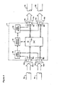
- Fig. 4 is a block diagram schematically illustrating the principal elements of an optical router 4 of the optical network.
- the optical router 4 is provided with two input ports 42a,b and two output ports 42c,d.
- a greater or smaller number of ports 42 may be provided in the optical router 4, and/or the optical router 4 may be provided with a plurality of ports 42 of which one or more may remain unused.
- the ports 42 of the optical router may be suitably designed and connected to handle bi-directional data traffic.
- the embodiment of Fig. 4 is provided with unidirectional ports two of which (input ports 2a,b) are connected to handle inbound frames, and the other two (output ports 42c,d) connected to handle outbound frames.
- an input port 42a is connected to receive inbound frames through a respective fiber optic link 6a.
- the input port 42a generally comprises an optical coupler 44a tuned to the label channel, and so receives the label block 18 of an inbound frame 16.
- the optical coupler 44a converts the label block 18 into an electrical signal which is passed to a label decoder 46.
- the input port 44a also provides a transparent optical connector 48a designed to guide the payload blocks 20 of an inbound frame 16 received over the data channels directly to an optical switch 50, without converting the optical signals into an electronic signal.
- the label decoder 46 receives the frame label (in electronic form) from the optical coupler 44a and decodes the frame label to extract the encoded routing information.
- the routing information is then passed by the label decoder 46 to a switch controller 52 which uses the routing information to select one of the output ports 42c,d for launching the frame 16 over a downstream link 6c,d for the next hop towards the destination of the frame 16. Selection of the output port may be made by known methods, for example as defined under the MPLS protocol. In the present example, the switch controller 52 selects the output port 42c for the next hop.
- the switch controller 52 then controls the optical switch 50, which may for example be an optical space switch, to set up a transparent optical path 54 (shown by a dashed line) between the input port 42a and the selected output port 42c.
- a transparent optical path 54 shown by a dashed line
- payload blocks 20 of the frame 16 arriving at the input port will be conducted across the optical router 4 to the output port 42c and launched into the downstream link 6c without interruption or conversion into electrical signals.
- the start time (TS) is predetermined and selected so that the delay period (D) between the launch of the first bit of the label block 18 and the first bit of the payload blocks 20 is sufficiently large to ensure that the label block 18 of an incoming frame 16 can be converted into an electrical signal at the input port optical coupler 44a, decoded by the label decoder 46, and then used by the switch controller 52 to establish the transparent optical path 54 through the optical switch 50 between the input port 42a and the selected output port 42c prior to arrival of the first bit of the payload blocks 20 of the incoming frame 16.
- the switch controller 52 can also control a label regenerator 56 which regenerates the frame label and launches a new label block 58 of the frame 16 (see Figs. 5 and 6 ) using an optical coupler 44c of the selected output port 42c.
- downstream link 6c In cases where the downstream link 6c is connected at its opposite end to an interface unit 22 such as shown in Fig. 3 , then preservation of the delay period (D) between the first bit of the label block 18 and the first bit of the payload blocks 20 of the outgoing frame 16 is not critical. However, in general, the downstream link 6c must be assumed to be connected at its opposite end to an input port 42 of another optical router 4. In this case, reliable transport of a frame 16 across the optical network 2 requires that the delay period (D) must be preserved across each link.
- the regenerated label constructed by the label regenerator 56 must be converted into an optical signal by the optical coupler 44c of the selected output port 42c and launched into the downstream link 6c as a new label block 58 at least a period of time (D) prior to arrival of the first bit of the payload blocks 20 at the selected output port 6c.
- D period of time
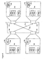
- an optical router 4 may comprise two (or more) input ports 42a,b connected to respective inbound links 6a,b. In such cases it is possible for respective frames 16a,b to arrive substantially simultaneously at respective input ports 42a,b of the optical router 4. Parallel decoding of the respective frame labels 18a,b within the label decoder 46 is readily possible, as is parallel set-up of transparent optical paths 54a,b through the optical switch under the control of the switch controller. As shown in Fig.
- the routing information encoded in the respective frame labels 18a,b is such that the transparent optical paths 54a,b are set up through the optical switch to respective different output ports 42c,d then the payload blocks 20a,b of each frame 16a,b can be conducted through the optical router 4 and launched into their respective downstream links 6c,d without difficulty.
- the routing information encoded in the respective frame labels 18a,b requires transparent optical guide paths to be established across the optical switch to a common output port 42c, the resulting contention between the inbound frames 16a,b must be resolved in order to prevent destructive interference of the inbound frames 10a,b.
- the use of comparatively short payload blocks 20 minimizes the probability of contention issues arising, by reducing the likelihood that frames 16a,b may arrive at different input ports 42a,b at the same time (or close enough in time that the respective sets of payload blocks 20a,b would overlap upon convergence of the two frames 16a,b into the downstream link 6c).
- An added measure of reliability can also be obtained by providing a delay loop 60 within the router 4.
- one of the transparent optical paths 54b can be routed through the optical switch 50 in such a way as to incorporate the delay loop 60.
- the delay loop 60 can conveniently be sized to impose a delay of a predetermined length, such as for example an integer multiple of the payload block length.
- the payload blocks 20b of one of the contending frames 16b will be delayed by the delay loop 60 for a time sufficient to permit the payload blocks 20a of the other frame 16a to clear the router 4 and be launched into the downstream link 6c. Because the payload blocks 20 of each frame 16 are a predetermined fixed length, this operation can reliably be performed even when the data packets being transported within each frame 16a,b are of different length. Thus it will be seen that the present invention facilitates full optical routing of variable length data packets.
Landscapes
- Engineering & Computer Science (AREA)
- Computer Networks & Wireless Communication (AREA)
- Signal Processing (AREA)
- Data Exchanges In Wide-Area Networks (AREA)
- Optical Communication System (AREA)
Claims (45)
- Procédé de routage de données par paquets de longueur variable à travers un réseau de communications optique (2) ayant une pluralité de voies de communications de données, caractérisé en ce que :a) un paquet de données subit un multiplexage inverse en une trame (16) comprenant :i) un bloc d'étiquette (18) contenant des informations d'étiquette de la trame ; etii) deux blocs de charge utile respectifs ou plus (20) ayant une longueur prédéterminée ;b) le bloc d'étiquette (18) est transmis sur une voie d'étiquette du réseau de communications ; etc) chaque bloc de charge utile (20) est transmis sur des voies de données séparées respectives du réseau de communications.
- Procédé selon la revendication 1, caractérisé en ce que le réseau de communications est un réseau optique de multiplexage par répartition en longueur d'onde (WDM).
- Procédé selon la revendication 2, caractérisé en ce que le réseau de communications est adapté pour le routage de commutation multiprotocole par étiquette (MPLS) du trafic de données par paquets.
- Procédé selon la revendication 3, caractérisé en ce que le trafic de données par paquets comprend l'un quelconque ou plusieurs de paquets de Protocole Internet (IP) et de trames en mode de transfert asynchrone (ATM).
- Procédé selon la revendication 3, caractérisé en ce qu'un nombre N de blocs de charge utile et la longueur prédéterminée de chaque bloc de charge utile de chaque trame sont sélectionnés sur la base d'une taille moyenne escomptée des paquets de données.
- Procédé selon la revendication 5, caractérisé en ce que l'étape de multiplexage inverse d'un paquet de données comprend l'étape consistant à diviser le paquet de données en N segments de paquet de taille sensiblement égale.
- Procédé selon la revendication 6, caractérisé en outre en ce que, lorsque la taille de chaque segment de paquet est inférieure ou égale à une capacité de chaque bloc de charge utile, une étape consistant à transmettre chaque segment de paquet à l'intérieur d'un bloc de charge utile respectif d'une seule trame.
- Procédé selon la revendication 6, caractérisé en outre en ce que, lorsque la taille de chaque segment de paquet est supérieure à une capacité de chaque bloc de charge utile :a) chaque segment de paquet est subdivisé en deux parties ou plus, chaque partie ayant une taille égale ou inférieure à la capacité d'un bloc de charge utile ; etb) chaque partie est transmise à l'intérieur de blocs de charge utile respectifs de trames successives respectives.
- Procédé selon la revendication 3, caractérisé en ce que le bloc d'étiquette comprend des informations codées concernant au moins un temps de départ et le routage à travers le réseau de la trame.
- Procédé selon la revendication 9, caractérisé en outre en ce que :a) le bloc d'étiquette d'une trame est reçu par l'intermédiaire d'un premier port d'un noeud de réseau ;b) le bloc d'étiquette est décodé pour obtenir les informations de routage ;c) un second port du noeud de réseau est sélectionné sur la base des informations de routage de la trame ; etd) un trajet optique transparent est établi entre les premier et second ports, de sorte que les blocs de charge utile de la trame soient guidés à travers le noeud de réseau via les premier et second ports.
- Procédé selon la revendication 10, caractérisé en ce que le temps de départ est indicatif d'une période de délai entre un temps d'arrivée d'un premier bit du bloc d'étiquette et un temps d'arrivée d'un premier bit des blocs de charge utile d'une trame.
- Procédé selon la revendication 11, caractérisé en ce que le temps de départ est sélectionné de sorte que l'étape consistant à établir le trajet optique transparent soit accomplie avant l'arrivée des blocs de charge utile de la trame au niveau du premier port du noeud de réseau.
- Procédé selon la revendication 12, caractérisé en ce que le bloc d'étiquette de la trame est regénéré, et le bloc d'étiquette regénéré est transmis sur la voie d'étiquette par l'intermédiaire du second port sélectionné.
- Procédé selon la revendication 13, caractérisé en ce que les blocs de charge utile de la trame sont retardés pendant une période de temps prédéterminée durant le passage des blocs de charge utile à travers le noeud de réseau entre les premier et second ports, la période prédéterminée étant sélectionnée pour conserver le temps de départ codé dans le bloc d'étiquette lorsque la trame traverse le noeud de réseau.
- Procédé selon la revendication 6, caractérisé en outre en ce que :a) une trame est reçue ; etb) les blocs de charge utile de la trame sont démultiplexés pour reconstruire le paquet de données.
- Procédé selon la revendication 15, caractérisé en ce que le bloc d'étiquette comprend des informations codées concernant un temps de fin indicatif d'une localisation d'un dernier bit du paquet de données à l'intérieur de la trame.
- Procédé selon la revendication 16, caractérisé en ce que le temps de fin est un nombre de bits du paquet de données.
- Procédé selon la revendication 16, caractérisé en ce que l'étape consistant à recevoir une trame comprend les étapes correspondant à :a) recevoir le bloc d'étiquette de la trame ;b) décoder le bloc d'étiquette pour extraire les informations de temps de fin ; etc) recevoir chaque bloc de charge utile de la trame.
- Procédé selon la revendication 16, caractérisé en ce que l'étape consistant à démultiplexer les blocs de charge utile de la trame comprend les étapes correspondant à :a) mettre en mémoire tampon les bits de chaque bloc de charge utile ;b) sélectionner des bits des blocs de charge utile reçus avant le temps de fin pour extraire chaque segment de données du paquet de données de son bloc de charge utile respectif ; etc) assembler les segments de données pour reconstruire le paquet de données.
- Procédé selon la revendication 19, caractérisé en outre en ce que les bits de la trame reçus après le temps de fin sont rejetés.
- Réseau de communications optique adapté pour la communication de paquets de données de taille variable, caractérisé par :a) une interface (24, 26, 32) adaptée au multiplexage inverse d'un paquet de données en une trame (16) comprenant :i) un bloc d'étiquette (18) contenant des informations d'étiquette de la trame ; etii) deux blocs de charge utile respectifs ou plus (20) ayant une longueur prédéterminée ;b) un premier coupleur optique (30) adapté pour transmettre le bloc d'étiquette (18) sur une voie d'étiquette du réseau de communications ; etc) un deuxième coupleur optique respectif (28) adapté pour transmettre chaque bloc de charge utile (20) sur une voie de données séparée respective du réseau de communications.
- Réseau de communications optique selon la revendication 21, caractérisé en ce que le premier coupleur optique est adapté pour transmettre le bloc d'étiquette à un même débit binaire que celui de chaque deuxième coupleur optique respectif.
- Réseau de communications optique selon la revendication 21, caractérisé en ce que le premier coupleur optique est adapté pour transmettre le bloc d'étiquette à un débit binaire inférieur à celui de chaque deuxième coupleur optique respectif.
- Réseau de communications optique selon la revendication 21, caractérisé en ce que le réseau de communications est un réseau optique de multiplexage par répartition en longueur d'onde (WDM).
- Réseau de communications optique selon la revendication 24, caractérisé en ce que le réseau de communications est adapté pour le routage de commutation multiprotocole par étiquette (MPLS) du trafic de données par paquets.
- Réseau de communications optique selon la revendication 25, caractérisé en ce que le trafic de données par paquets comprend l'un quelconque ou plusieurs de paquets de Protocole Internet (IP) et de trames en mode de transfert asynchrone (ATM).
- Réseau de communications optique selon la revendication 26, caractérisé en ce qu'un nombre N de blocs de charge utile et la longueur prédéterminée de chaque bloc de charge utile de chaque trame sont sélectionnés sur la base d'une taille moyenne escomptée des paquets de données.
- Réseau de communications optique selon la revendication 27, caractérisé en ce que l'interface est adaptée pour diviser le paquet de données en N segments de paquet de taille sensiblement égale.
- Réseau de communications optique selon la revendication 28, caractérisé en ce que, lorsque la taille de chaque segment de paquet est inférieure ou égale à une capacité de chaque bloc de charge utile, l'interface est adaptée pour transmettre chaque segment de paquet à l'intérieur d'un bloc de charge utile respectif d'une seule trame.
- Réseau de communications optique selon la revendication 28, caractérisé en ce que, lorsque la taille de chaque segment de paquet est supérieure à une capacité de chaque bloc de charge utile, l'interface est adaptée pour :a) subdiviser chaque segment de paquet en deux parties ou plus, chaque partie ayant une taille égale ou inférieure à la capacité d'un bloc de charge utile ; etb) transmettre chaque partie à l'intérieur de blocs de charge utile respectifs de trames successives respectives.
- Réseau de communications optique selon la revendication 25, caractérisé en ce que l'interface comprend en outre un générateur d'étiquette adapté pour générer le bloc d'étiquette incluant des informations codées concernant au moins un temps de départ et le routage de la trame à travers le réseau.
- Réseau de communications optique selon la revendication 31, caractérisé en ce que le temps de départ est indicatif d'une période de délai entre la transmission d'un premier bit du bloc d'étiquette par le premier coupleur optique et la transmission d'un premier bit des blocs de charge utile par les deuxièmes coupleurs optiques respectifs.
- Réseau de communications optique selon la revendication 32, comprenant en outre un noeud de réseau adapté pour router des trames entre une première et une seconde liaison du réseau de communications, caractérisé par :a) un décodeur d'étiquette adapté pour décoder un bloc d'étiquette d'une trame reçu sur la voie d'étiquette par l'intermédiaire d'un port d'entrée connecté à la première liaison ;b) un contrôleur sensible au décodeur d'étiquette pour générer un signal de commande de routage ;c) un commutateur sensible au signal de commande de routage pour établir un trajet optique transparent entre le port d'entrée et un port de sortie sélectionné connecté à la seconde liaison ; etd) un regénérateur d'étiquette adapté pour regénérer un bloc d'étiquette de la trame pour la transmission sur la voie d'étiquette par l'intermédiaire du port de sortie sélectionné.
- Réseau de communications optique selon la revendication 33, caractérisé en ce que le temps de départ est sélectionné de sorte que le commutateur ait suffisamment de temps pour établir le trajet optique transparent avant l'arrivée des blocs de charge utile de la trame au niveau du premier port du noeud de réseau.
- Réseau de communications optique selon la revendication 33, caractérisé en ce que le noeud de réseau comprend en outre un troisième coupleur optique adapté pour transmettre le bloc d'étiquette regénéré sur la voie d'étiquette par l'intermédiaire du port de sortie sélectionné.
- Réseau de communications optique selon la revendication 33, caractérisé en outre par des moyens de retard adaptes pour retarder les blocs de charge utile de la trame pendant une période de temps prédéterminée durant le passage des blocs de charge utile à travers le noeud de réseau entre les ports d'entrée et de sortie, la période prédéterminée étant sélectionnée pour conserver le temps de départ codé dans le bloc d'étiquette de la trame lorsqu'elle traverse le noeud de réseau.
- Routeur pour router le trafic de données par paquets entre une première et une seconde liaison d'un réseau de communications optique adapté pour la communication de paquets de données ayant une longueur variable, les paquets de données étant transportés à l'intérieur de trames (16) comprenant un bloc d'étiquette (18) et deux blocs de charge utile ou plus (20) ayant une longueur prédéterminée, le bloc d'étiquette étant acheminé sur une voie d'étiquette du réseau de communications, et les blocs de charge utile étant acheminés sensiblement en parallèle sur des voies de données séparées respectives du réseau de communications, le routeur incluant au moins un port d'entrée (42a,b) connecté à la première liaison (6a,b) pour recevoir des trames séquentielles, et au moins un port de sortie (42c,d) connecté à la seconde liaison (6c,d) pour lancer des trames séquentielles dans la seconde liaison, et comprenant en outre :a) un décodeur d'étiquette (46) adapté pour décoder un bloc d'étiquette reçu sur la voie d'étiquette par l'intermédiaire d'un port d'entrée ;b) un contrôleur (52) sensible au décodeur d'étiquette (46) pour générer un signal de commande de routage indicatif d'un port de sortie sélectionné ;c) un commutateur (50) sensible au signal de commande de routage pour établir un trajet optique transparent entre le port d'entrée et le port de sortie sélectionné ; etd) un regénérateur d'étiquette (56) adapté pour regénérer le bloc d'étiquette pour l'envoi sur la voie d'étiquette par l'intermédiaire du port de sortie sélectionné.
- Routeur selon la revendication 37, caractérisé en ce que le réseau de communications est un réseau optique de multiplexage par répartition en longueur d'onde (WDM).
- Routeur selon la revendication 38, caractérisé en ce que le routeur est adapté pour le routage de commutation multiprotocole par étiquette (MPLS) du trafic de données par paquets.
- Routeur selon la revendication 39, caractérisé en ce que le trafic de données par paquets comprend l'un quelconque ou plusieurs de paquets de Protocole Internet (IP) et de trames en mode de transfert asynchrone (ATM).
- Routeur selon la revendication 39, caractérisé en ce que le bloc d'étiquette inclut des informations codées concernant au moins un temps de départ et le routage de la trame à travers le réseau.
- Routeur selon la revendication 41, caractérisé en ce que le temps de départ est indicatif d'une période de délai minimum entre l'arrivée d'un premier bit du bloc d'étiquette et l'arrivée d'un premier bit des blocs de charge utile au niveau du port d'entrée.
- Routeur selon la revendication 42, caractérisé en ce que le temps de départ est sélectionné de sorte que le commutateur ait suffisamment de temps pour établir le trajet optique transparent avant l'arrivée des blocs de charge utile de la trame au niveau du port d'entrée.
- Routeur selon la revendication 43, caractérisé en outre par un coupleur optique adapté pour transmettre le bloc d'étiquette regénéré sur la voie d'étiquette par l'intermédiaire du port de sortie sélectionné.
- Routeur selon la revendication 43, caractérisé en outre par des moyens de retard adaptés pour retarder les blocs de charge utile de la trame pendant une période de temps prédéterminée durant le passage des blocs de charge utile à travers le noeud de réseau entre les ports d'entrée et de sortie, la période prédéterminée étant sélectionnée pour conserver le temps de départ codé dans le bloc d'étiquette de la trame lorsqu'elle traverse le noeud de réseau.
Applications Claiming Priority (2)
| Application Number | Priority Date | Filing Date | Title |
|---|---|---|---|
| US501517 | 2000-02-09 | ||
| US09/501,517 US6839322B1 (en) | 2000-02-09 | 2000-02-09 | Method and system for optical routing of variable-length packet data |
Publications (3)
| Publication Number | Publication Date |
|---|---|
| EP1126740A2 EP1126740A2 (fr) | 2001-08-22 |
| EP1126740A3 EP1126740A3 (fr) | 2005-11-30 |
| EP1126740B1 true EP1126740B1 (fr) | 2009-07-01 |
Family
ID=23993877
Family Applications (1)
| Application Number | Title | Priority Date | Filing Date |
|---|---|---|---|
| EP01301171A Expired - Lifetime EP1126740B1 (fr) | 2000-02-09 | 2001-02-09 | Procédé et système de routage optique de paquets de longueur variable |
Country Status (4)
| Country | Link |
|---|---|
| US (2) | US6839322B1 (fr) |
| EP (1) | EP1126740B1 (fr) |
| CA (1) | CA2334549C (fr) |
| DE (1) | DE60139095D1 (fr) |
Families Citing this family (60)
| Publication number | Priority date | Publication date | Assignee | Title |
|---|---|---|---|---|
| CN1214588C (zh) * | 1999-05-25 | 2005-08-10 | 索尼公司 | 传送方法、传送装置及传送系统 |
| KR100612003B1 (ko) * | 2000-02-26 | 2006-08-11 | 삼성전자주식회사 | 통신망에서 비트 스트림 송수신 장치 및 그 방법 |
| US6795605B1 (en) * | 2000-08-01 | 2004-09-21 | Cheetah Omni, Llc | Micromechanical optical switch |
| US7613183B1 (en) | 2000-10-31 | 2009-11-03 | Foundry Networks, Inc. | System and method for router data aggregation and delivery |
| JP2002152259A (ja) * | 2000-11-13 | 2002-05-24 | Yozan Inc | 通信端末装置および課金処理装置 |
| US20020085563A1 (en) * | 2001-01-03 | 2002-07-04 | Michael Mesh | Packet processing method and engine |
| US7145704B1 (en) * | 2003-11-25 | 2006-12-05 | Cheetah Omni, Llc | Optical logic gate based optical router |
| US7315900B1 (en) * | 2001-06-20 | 2008-01-01 | Juniper Networks, Inc. | Multi-link routing |
| JP2003078497A (ja) * | 2001-09-04 | 2003-03-14 | Fujitsu Ltd | 伝送装置 |
| US7110671B1 (en) * | 2001-12-03 | 2006-09-19 | Cheetah Omni, Llc | Method and apparatus for scheduling communication using a star switching fabric |
| US7079528B2 (en) * | 2001-12-13 | 2006-07-18 | International Business Machines Corporation | Data communication method |
| US8660427B2 (en) * | 2002-09-13 | 2014-02-25 | Intel Corporation | Method and apparatus of the architecture and operation of control processing unit in wavelenght-division-multiplexed photonic burst-switched networks |
| US8315518B1 (en) | 2002-09-18 | 2012-11-20 | Ciena Corporation | Technique for transmitting an optical signal through an optical network |
| US20040062195A1 (en) * | 2002-09-30 | 2004-04-01 | Intel Corporation | Algorithm for dynamic provisioning of fail-over support in generalized multi-protocol label switching enabled networks |
| US7428383B2 (en) * | 2003-02-28 | 2008-09-23 | Intel Corporation | Architecture, method and system of WDM-based photonic burst switched networks |
| US7848649B2 (en) * | 2003-02-28 | 2010-12-07 | Intel Corporation | Method and system to frame and format optical control and data bursts in WDM-based photonic burst switched networks |
| US7298973B2 (en) * | 2003-04-16 | 2007-11-20 | Intel Corporation | Architecture, method and system of multiple high-speed servers to network in WDM based photonic burst-switched networks |
| US7266295B2 (en) * | 2003-04-17 | 2007-09-04 | Intel Corporation | Modular reconfigurable multi-server system and method for high-speed networking within photonic burst-switched network |
| US7526202B2 (en) | 2003-05-19 | 2009-04-28 | Intel Corporation | Architecture and method for framing optical control and data bursts within optical transport unit structures in photonic burst-switched networks |
| US7266296B2 (en) * | 2003-06-11 | 2007-09-04 | Intel Corporation | Architecture and method for framing control and data bursts over 10 Gbit Ethernet with and without WAN interface sublayer support |
| US7310480B2 (en) * | 2003-06-18 | 2007-12-18 | Intel Corporation | Adaptive framework for closed-loop protocols over photonic burst switched networks |
| US7315549B2 (en) * | 2003-07-24 | 2008-01-01 | Intel Corporation | Formatting data for a buffer |
| US20050030951A1 (en) * | 2003-08-06 | 2005-02-10 | Christian Maciocco | Reservation protocol signaling extensions for optical switched networks |
| US20050068968A1 (en) * | 2003-09-30 | 2005-03-31 | Shlomo Ovadia | Optical-switched (OS) network to OS network routing using extended border gateway protocol |
| US7315693B2 (en) * | 2003-10-22 | 2008-01-01 | Intel Corporation | Dynamic route discovery for optical switched networks |
| US7340169B2 (en) * | 2003-11-13 | 2008-03-04 | Intel Corporation | Dynamic route discovery for optical switched networks using peer routing |
| US20050135612A1 (en) * | 2003-12-19 | 2005-06-23 | Evans Alan F. | Secure digital communication |
| US7734176B2 (en) * | 2003-12-22 | 2010-06-08 | Intel Corporation | Hybrid optical burst switching with fixed time slot architecture |
| US20050177749A1 (en) * | 2004-02-09 | 2005-08-11 | Shlomo Ovadia | Method and architecture for security key generation and distribution within optical switched networks |
| US20050175183A1 (en) * | 2004-02-09 | 2005-08-11 | Shlomo Ovadia | Method and architecture for secure transmission of data within optical switched networks |
| US7321597B2 (en) * | 2004-03-18 | 2008-01-22 | Jeknouus, Inc. | Method and apparatus for remote network management over ethernet connections |
| FR2868226B1 (fr) * | 2004-03-29 | 2006-05-26 | Philippe Joliot | Procede de transmission d'un fichier de donnees numeriques au travers de reseaux de telecommunications ou de radiocommunications |
| US7515543B2 (en) * | 2004-12-21 | 2009-04-07 | Alcatel-Lucent Usa Inc. | Packet reorder resolution in a load-balanced network architecture |
| JP3961000B2 (ja) * | 2005-05-26 | 2007-08-15 | 株式会社日立コミュニケーションテクノロジー | パケット転送装置及びネットワークシステム |
| US7706685B2 (en) * | 2005-09-20 | 2010-04-27 | Lockheed Martin Corporation | Data communication network using optical power averaged multiplexing |
| US8670309B2 (en) * | 2005-09-30 | 2014-03-11 | Alcatel Lucent | Method and apparatus for preventing activation of a congestion control process |
| JP4938890B2 (ja) * | 2007-05-10 | 2012-05-23 | テレフオンアクチーボラゲット エル エム エリクソン(パブル) | 光ノード |
| US8411681B2 (en) * | 2008-12-10 | 2013-04-02 | Electronics And Telecommunications Research Institute | Multicasting method in network including T-MPLS network and WDM network and apparatus therefor |
| KR101252825B1 (ko) | 2008-12-10 | 2013-04-11 | 한국전자통신연구원 | T-mpls망과 wdm망으로 구성된 네트워크에서의 멀티캐스팅 방법 및 그를 위한 장치 |
| US20110318004A1 (en) * | 2008-12-23 | 2011-12-29 | Telefonaktiebolaget L M Ericsson (Publ) | Transmission and routing of optical signals |
| JP5439355B2 (ja) * | 2010-12-28 | 2014-03-12 | 富士通テレコムネットワークス株式会社 | 光パケットスイッチ装置 |
| JP2012165267A (ja) * | 2011-02-08 | 2012-08-30 | Fujitsu Telecom Networks Ltd | 光パケット交換システムおよび光パケット交換装置 |
| WO2013033448A1 (fr) * | 2011-08-30 | 2013-03-07 | University Of Houston | Procédés et appareils pour routeur de commutation multimode dwdm et pour configuration et reconfiguration multimode dynamiques |
| US9148250B2 (en) | 2012-06-30 | 2015-09-29 | Intel Corporation | Methods and arrangements for error correction in decoding data from an electromagnetic radiator |
| US9218532B2 (en) | 2012-09-28 | 2015-12-22 | Intel Corporation | Light ID error detection and correction for light receiver position determination |
| US9178615B2 (en) * | 2012-09-28 | 2015-11-03 | Intel Corporation | Multiphase sampling of modulated light with phase synchronization field |
| US9590728B2 (en) | 2012-09-29 | 2017-03-07 | Intel Corporation | Integrated photogrammetric light communications positioning and inertial navigation system positioning |
| JP6007747B2 (ja) * | 2012-11-20 | 2016-10-12 | 富士通株式会社 | データ受信装置、dpll装置及びデータ受信装置制御方法 |
| US9065747B2 (en) * | 2012-12-28 | 2015-06-23 | Infinera Corp. | Network interface and method of aggregating processor circuits |
| KR20160006766A (ko) * | 2013-05-10 | 2016-01-19 | 후아웨이 테크놀러지 컴퍼니 리미티드 | 광 스위칭을 위한 시스템 및 방법 |
| GB201411366D0 (en) * | 2014-06-26 | 2014-08-13 | Univ Warwick | Controlling packet flow in a network |
| TWI564722B (zh) * | 2014-12-12 | 2017-01-01 | 環鴻科技股份有限公司 | 硬碟背板及其串列通用輸入輸出訊號的偵測方法 |
| US10750255B2 (en) | 2016-04-22 | 2020-08-18 | Huawei Technologies Co., Ltd. | Segment routing for optical networks |
| US20170373881A1 (en) * | 2016-06-27 | 2017-12-28 | Qualcomm Incorporated | Systems and methods for controlling isochronous data streams |
| JP2018191033A (ja) * | 2017-04-28 | 2018-11-29 | ルネサスエレクトロニクス株式会社 | 無線送信装置、無線受信装置、及び無線送信方法 |
| GB2597487A (en) * | 2020-07-23 | 2022-02-02 | British Telecomm | Optical network configuration |
| US11627185B1 (en) * | 2020-09-21 | 2023-04-11 | Amazon Technologies, Inc. | Wireless data protocol |
| US12250502B2 (en) * | 2022-04-05 | 2025-03-11 | University Of Southern California | Remotely biasing, controlling, and monitoring a network routing node based on remotely provided optical signals |
| US12219304B2 (en) * | 2022-10-27 | 2025-02-04 | Cisco Technology, Inc. | Packet switched quantum network |
| US12615216B2 (en) * | 2023-11-29 | 2026-04-28 | Cisco Technology, Inc. | Coalescing public internet packets into jumbo frames between SD-WAN provider network services |
Family Cites Families (20)
| Publication number | Priority date | Publication date | Assignee | Title |
|---|---|---|---|---|
| DE69013886T2 (de) * | 1990-04-11 | 1995-05-18 | Ibm | Mehrfachzugriffssteuerung für ein Kommunikationssystem mit Reservierungsblockübermittlung. |
| SG48849A1 (en) * | 1992-04-09 | 1998-05-18 | British Telecomm | Optical processing system |
| KR0148153B1 (ko) * | 1994-05-31 | 1998-09-15 | 김광호 | 비트스터핑 제거장치 |
| JP3651941B2 (ja) * | 1994-11-28 | 2005-05-25 | キヤノン株式会社 | 画像再生装置 |
| KR100192651B1 (ko) * | 1994-12-07 | 1999-06-15 | 가나이 쓰도무 | 제어셀에 의해 입력셀의 전송을 제어하는 atm교환망, atm교환기 및 atm교환망에 있어서의 신호처리방법 |
| US5617233A (en) | 1995-09-28 | 1997-04-01 | The United States Of America As Represented By The Secretary Of The Air Force | Transparent optical node structure |
| US5917828A (en) * | 1997-01-03 | 1999-06-29 | Ncr Corporation | ATM reassembly controller and method |
| JP2962276B2 (ja) * | 1997-05-12 | 1999-10-12 | 日本電気株式会社 | Atmコネクションレス通信網におけるセッション管理方式及びコネクション管理方式 |
| US6021419A (en) * | 1997-09-16 | 2000-02-01 | International Business Machines Corporation | System for filtering broadcast digital information in accordance with channel identifiers stored in preference list which can be dynamically updated via command through network |
| US6160819A (en) * | 1998-02-19 | 2000-12-12 | Gte Internetworking Incorporated | Method and apparatus for multiplexing bytes over parallel communications links using data slices |
| US6374314B1 (en) * | 1998-09-28 | 2002-04-16 | Raytheon Company | Method for managing storage of data by storing buffer pointers of data comprising a sequence of frames in a memory location different from a memory location for pointers of data not comprising a sequence of frames |
| US7340183B2 (en) * | 1998-11-17 | 2008-03-04 | Broadwing Corporation | Optical communications systems, devices, and methods |
| US6222858B1 (en) * | 1999-02-10 | 2001-04-24 | Verizon Laboratories Inc. | Method of inverse multiplexing for ATM |
| US6331978B1 (en) * | 1999-03-09 | 2001-12-18 | Nokia Telecommunications, Oy | Generic label encapsulation protocol for carrying label switched packets over serial links |
| US6433904B1 (en) * | 1999-07-27 | 2002-08-13 | Sycamore Networks, Inc. | Method and apparatus for improving transmission performance over wavelength division multiplexed optical communication links using forward error correction coding |
| US6721315B1 (en) * | 1999-09-30 | 2004-04-13 | Alcatel | Control architecture in optical burst-switched networks |
| US6819870B1 (en) * | 1999-11-02 | 2004-11-16 | Alcatel | All-optical networking optical fiber line delay buffering apparatus and method |
| US20020054732A1 (en) * | 1999-11-02 | 2002-05-09 | Zheng Si Q. | Optical burst scheduling using partitioned channel groups |
| US6519062B1 (en) * | 2000-02-29 | 2003-02-11 | The Regents Of The University Of California | Ultra-low latency multi-protocol optical routers for the next generation internet |
| US7065103B1 (en) * | 2000-04-19 | 2006-06-20 | Nortel Networks Limited | Hyper-concatenation across multiple parallel channels |
-
2000
- 2000-02-09 US US09/501,517 patent/US6839322B1/en not_active Expired - Lifetime
-
2001
- 2001-02-08 CA CA002334549A patent/CA2334549C/fr not_active Expired - Fee Related
- 2001-02-09 DE DE60139095T patent/DE60139095D1/de not_active Expired - Lifetime
- 2001-02-09 EP EP01301171A patent/EP1126740B1/fr not_active Expired - Lifetime
-
2004
- 2004-10-18 US US10/965,828 patent/US7869362B2/en not_active Expired - Fee Related
Also Published As
| Publication number | Publication date |
|---|---|
| US7869362B2 (en) | 2011-01-11 |
| DE60139095D1 (de) | 2009-08-13 |
| EP1126740A2 (fr) | 2001-08-22 |
| US6839322B1 (en) | 2005-01-04 |
| EP1126740A3 (fr) | 2005-11-30 |
| CA2334549A1 (fr) | 2001-08-09 |
| US20050047392A1 (en) | 2005-03-03 |
| CA2334549C (fr) | 2009-06-16 |
Similar Documents
| Publication | Publication Date | Title |
|---|---|---|
| EP1126740B1 (fr) | Procédé et système de routage optique de paquets de longueur variable | |
| JP3578960B2 (ja) | 超高速光パケット転送リングネットワーク、光挿入分岐型多重分離ノード装置及び光挿入分岐型多重分離ノード装置の動作方法 | |
| US6940863B2 (en) | Edge router for optical label switched network | |
| US20020057861A1 (en) | Optical IP switching router architecture | |
| US20050078659A1 (en) | Label selection for end-to-end label-switched traffic through a communications network | |
| EP1445975B1 (fr) | Routeur optique à grande capacité utilisant une mémoire tampon électrique | |
| US7181140B2 (en) | Method and apparatus for implementing and networking a semiconductor-based optical burst switching module within optical networks | |
| US7376138B1 (en) | Optical communications network | |
| EP1266472B1 (fr) | Procede de transfert optique d'informations par paquets au moyen de longueurs d'ondes differentes pour les informations d'adresse et les informations utiles | |
| EP1158711B1 (fr) | Concaténer virtuellement à travers de processeurs indépendants de pointeurs | |
| US8594130B2 (en) | Method and system for shortening the length of time gaps between data units in a data switching network | |
| WO2001084875A2 (fr) | Transport efficace de trafic ip via mrl par commutation optique de rafales | |
| EP1686734A1 (fr) | Procédé et dispositif pour transmettre un signal optique dans un réseau optique par rafales utilisant le temps d'arrivée | |
| JP3546797B2 (ja) | 普遍的データリンクプロトコールを用いた通信装置 | |
| EP1052808A1 (fr) | Réseau de communication utilisant classes de priorité | |
| Salvador et al. | An all-optical WDM packet-switched network architecture with support for group communication | |
| US20030016671A1 (en) | Wavelength division multiplexed network with frame switching | |
| JP2017204821A (ja) | 光集線ネットワークシステム、光伝送装置及び光伝送方法 | |
| WO2000042739A1 (fr) | Systeme et procede de simulation d'une topologie de reseau en etoile | |
| KR101106096B1 (ko) | 리피터 및 브리지 기능이 혼합된 오디오 및 데이터 중계 방법 및 그 실시를 위한 중계 시스템 | |
| EP1052807A1 (fr) | Réseau de communications utilisant classes de priorité | |
| Xu et al. | Transporting IP packets over light: a survey | |
| Wu et al. | An effective implementation scheme of just-in-time protocol for optical burst switching networks | |
| US20020131671A1 (en) | Fibre optic switching device |
Legal Events
| Date | Code | Title | Description |
|---|---|---|---|
| PUAI | Public reference made under article 153(3) epc to a published international application that has entered the european phase |
Free format text: ORIGINAL CODE: 0009012 |
|
| AK | Designated contracting states |
Kind code of ref document: A2 Designated state(s): AT BE CH CY DE DK ES FI FR GB GR IE IT LI LU MC NL PT SE TR |
|
| AX | Request for extension of the european patent |
Free format text: AL;LT;LV;MK;RO;SI |
|
| RAP1 | Party data changed (applicant data changed or rights of an application transferred) |
Owner name: NORTEL NETWORKS LIMITED |
|
| PUAL | Search report despatched |
Free format text: ORIGINAL CODE: 0009013 |
|
| AK | Designated contracting states |
Kind code of ref document: A3 Designated state(s): AT BE CH CY DE DK ES FI FR GB GR IE IT LI LU MC NL PT SE TR |
|
| AX | Request for extension of the european patent |
Extension state: AL LT LV MK RO SI |
|
| 17P | Request for examination filed |
Effective date: 20060307 |
|
| AKX | Designation fees paid |
Designated state(s): DE FR GB |
|
| 17Q | First examination report despatched |
Effective date: 20061011 |
|
| GRAP | Despatch of communication of intention to grant a patent |
Free format text: ORIGINAL CODE: EPIDOSNIGR1 |
|
| GRAS | Grant fee paid |
Free format text: ORIGINAL CODE: EPIDOSNIGR3 |
|
| GRAA | (expected) grant |
Free format text: ORIGINAL CODE: 0009210 |
|
| AK | Designated contracting states |
Kind code of ref document: B1 Designated state(s): DE FR GB |
|
| REG | Reference to a national code |
Ref country code: GB Ref legal event code: FG4D |
|
| REF | Corresponds to: |
Ref document number: 60139095 Country of ref document: DE Date of ref document: 20090813 Kind code of ref document: P |
|
| PLBE | No opposition filed within time limit |
Free format text: ORIGINAL CODE: 0009261 |
|
| STAA | Information on the status of an ep patent application or granted ep patent |
Free format text: STATUS: NO OPPOSITION FILED WITHIN TIME LIMIT |
|
| 26N | No opposition filed |
Effective date: 20100406 |
|
| REG | Reference to a national code |
Ref country code: FR Ref legal event code: PLFP Year of fee payment: 16 |
|
| PGFP | Annual fee paid to national office [announced via postgrant information from national office to epo] |
Ref country code: DE Payment date: 20160202 Year of fee payment: 16 |
|
| PGFP | Annual fee paid to national office [announced via postgrant information from national office to epo] |
Ref country code: GB Payment date: 20160203 Year of fee payment: 16 Ref country code: FR Payment date: 20160108 Year of fee payment: 16 |
|
| REG | Reference to a national code |
Ref country code: DE Ref legal event code: R119 Ref document number: 60139095 Country of ref document: DE |
|
| GBPC | Gb: european patent ceased through non-payment of renewal fee |
Effective date: 20170209 |
|
| REG | Reference to a national code |
Ref country code: FR Ref legal event code: ST Effective date: 20171031 |
|
| PG25 | Lapsed in a contracting state [announced via postgrant information from national office to epo] |
Ref country code: FR Free format text: LAPSE BECAUSE OF NON-PAYMENT OF DUE FEES Effective date: 20170228 Ref country code: DE Free format text: LAPSE BECAUSE OF NON-PAYMENT OF DUE FEES Effective date: 20170901 |
|
| PG25 | Lapsed in a contracting state [announced via postgrant information from national office to epo] |
Ref country code: GB Free format text: LAPSE BECAUSE OF NON-PAYMENT OF DUE FEES Effective date: 20170209 |