EP1126920B1 - Bewegung einer sprühpistole gemäss einer achtförmigen bahn - Google Patents
Bewegung einer sprühpistole gemäss einer achtförmigen bahn Download PDFInfo
- Publication number
- EP1126920B1 EP1126920B1 EP99971741A EP99971741A EP1126920B1 EP 1126920 B1 EP1126920 B1 EP 1126920B1 EP 99971741 A EP99971741 A EP 99971741A EP 99971741 A EP99971741 A EP 99971741A EP 1126920 B1 EP1126920 B1 EP 1126920B1
- Authority
- EP
- European Patent Office
- Prior art keywords
- gear
- motor
- axle
- arm
- follower
- Prior art date
- Legal status (The legal status is an assumption and is not a legal conclusion. Google has not performed a legal analysis and makes no representation as to the accuracy of the status listed.)
- Expired - Lifetime
Links
Images



Classifications
-
- B—PERFORMING OPERATIONS; TRANSPORTING
- B05—SPRAYING OR ATOMISING IN GENERAL; APPLYING FLUENT MATERIALS TO SURFACES, IN GENERAL
- B05B—SPRAYING APPARATUS; ATOMISING APPARATUS; NOZZLES
- B05B13/00—Machines or plants for applying liquids or other fluent materials to surfaces of objects or other work by spraying, not covered by groups B05B1/00 - B05B11/00
- B05B13/02—Means for supporting work; Arrangement or mounting of spray heads; Adaptation or arrangement of means for feeding work
- B05B13/04—Means for supporting work; Arrangement or mounting of spray heads; Adaptation or arrangement of means for feeding work the spray heads being moved during spraying operation
-
- B—PERFORMING OPERATIONS; TRANSPORTING
- B05—SPRAYING OR ATOMISING IN GENERAL; APPLYING FLUENT MATERIALS TO SURFACES, IN GENERAL
- B05B—SPRAYING APPARATUS; ATOMISING APPARATUS; NOZZLES
- B05B7/00—Spraying apparatus for discharge of liquids or other fluent materials from two or more sources, e.g. of liquid and air, of powder and gas
- B05B7/16—Spraying apparatus for discharge of liquids or other fluent materials from two or more sources, e.g. of liquid and air, of powder and gas incorporating means for heating or cooling the material to be sprayed
- B05B7/20—Spraying apparatus for discharge of liquids or other fluent materials from two or more sources, e.g. of liquid and air, of powder and gas incorporating means for heating or cooling the material to be sprayed by flame or combustion
Definitions
- This invention relates to thermal spraying, and particularly to apparatus for moving thermal spray guns over substrates.
- An apparatus for moving a spray gun comprising the features of the preamble of claim 1 is known from US5660 633 .
- Thermal spraying also known as flame spraying, involves the melting or at least heat softening of a heat fusible material such as a metal or ceramic, and propelling the softened material in particulate form against a surface which is to be coated. The heated particles strike the surface where they are quenched and bonded thereto to produce a coating.
- a plasma type of thermal spray gun a plasma stream, formed of nitrogen or argon heated by a high intensity arc, melts and propels powder particles.
- Other types of thermal spray guns include a combustion spray gun in which powder is entrained and heated in a combustion flame, either at nominal velocity or in a high velocity oxy-fuel (HVOF) gun.
- HVOF high velocity oxy-fuel
- a wire In a wire type of gun a wire is fed through a combustion flame where a melted wire tip is atomized by compressed air into a fine spray for deposit.
- a two-wire arc gun melts contacting wire tips with an electrical arc for atomization by compressed air.
- traversing equipment have been taught or used to traverse or scan a spray deposit over a relatively large substrate to produce as uniform a coating as practical. These include equipment designed to traverse and index the gun automatically in an x-y plane over preset areas, and robots with multiple linear and rotational axes particularly for complex shapes.
- Uniform thickness is easier to achieve for coating a shaft which may be rotated at high speed while the spray gun is traversed back and forth along the shaft.
- the gun On flat or large curved areas the gun generally is waved or moved back and forth while it is traversed in a direction generally perpendicular to the waving motion.
- a problem is that, during a cycle, the gun must be stopped at each end of the wave to reverse direction. The spray stream lingers longer near each of these points causing a much thicker layer to be deposited at each end.
- An additional problem is a hot spot that can develop at each point of lingering, thus overheating the coating and substrate to cause detrimental oxidation and other metallurgical changes. This is particularly acute for an HVOF type of gun which produces a relatively narrow spray stream and small deposit spot.
- the gun can be moved off the edge of the substrate for each reversal, but this results in loss of spray material which can be expensive, and can require masking to prevent unwanted areas to be coated.
- Multiple cycles of traversing with overlapping layers have been utilized for smoothing out the thickness variations, but often with only partial success because of the complex programming required to compensate a varying thickness profile.
- Such programming is even more extensive for complex shapes. Even programming of a robot can be time and memory consuming, and thus quite expensive for each different type of substrate to be coated.
- Circular and oval patterns result in substantially thicker coatings at the edges when the patterns are traversed.
- Figure eight patterns are better in this regard.
- a figure eight pattern with uniform velocity of travel of the deposit may be programmed into a robot, but this was found by the present inventors to be extremely complex and time consuming and, therefore, is believed not to have general practicality.
- Mechanisms such as with linked gearing and arms or cams can produce a figure eight motion which is an improvement over linear waving motion with regard to deposit thickness.
- simple mechanisms typically have variations in velocity of travel along the configuration of the figure eight, particularly slowing down along the distal ends of the figure, thus negating some of the advantage. Thus such mechanisms do not fully solve the problem.
- a thermal spray gun particularly an HVOF type, should have its deposit spot moved along a substrate at a relatively high velocity. Any apparatus dedicated to moving the gun must be quite robust, and should remain simple to achieve this.
- An object of the invention is to provide a novel apparatus for moving a thermal spray gun over a substrate, particularly a large area substrate. Another object is to provide such an apparatus for producing improvements in uniformity of coating thickness. Yet another object is to reduce overheating of spots in the coating during deposition. A further object is to provide such an apparatus for moving a thermal spray gun in a figure eight motion, with improvement wherein the travel of the deposit along the figure eight has reduced non-uniformity in velocity, with corresponding reductions in non-uniformity in coating thickness and in heating during deposition. Another object is to provide such an apparatus that is robust and capable of continuous, rapid motions.
- an apparatus for moving a spray stream from a thermal spray gun over a substrate comprising a support body, a figure eight mechanism and a drive system.
- the figure eight mechanism is affixed to the body and has a mounting thereon for a thermal spray gun that effects a spray stream to produce a deposit on a substrate.
- the mechanism is operational to effect a figure eight motion to the gun and thereby to the spray stream such that the deposit travels in a deposit pattern with a figure eight configuration.
- the mechanism has an input member such as an axle or gear receptive of an input drive to operate the mechanism.
- the mechanism is such that, when driven by an input drive of constant speed, the deposit travels along the configuration at a velocity with non-uniformity.
- the drive system is engaged with the input member to provide an input drive with varying speed so as to reduce the non-uniformity of the velocity, such that, with a thermal spray gun mounted to the mechanism and with the support body mounted onto a traversing device that traverses the mechanism and thereby the thermal spray gun, the deposit pattern is traversed along the substrate to effect a coating of substantially uniform thickness on the substrate.
- the drive system comprises a motor and a linkage connected between the motor and the input member.
- the linkage comprises a proportionate drive between the motor and the input member such that the input member speed is equal to or proportional to the motor speed
- the drive system further comprises a motor control connected to operate the motor at a varying speed so as to reduce the non-uniformity of the velocity along the figure eight configuration.
- the motor operates at constant speed
- the linkage translates the constant speed of the motor to varying speed at the input member to reduce the non-uniformity of the velocity of the deposit.
- a figure eight mechanism 12 is affixed to a support body 14.
- the mechanism is operated by a drive system 16 also affixed to the body.
- the mechanism includes a mounting member 18 with threaded holes 20 therein for screws to retain a thermal spray gun 22 that generates a spray stream 24 of coating material directed to a substrate 26 to produce a deposit 27 thereon.
- the apparatus is particularly suitable to manipulate such a gun for coating a large area substrate which, for example, may be flat, or have a curvature such as in a turbine blade, or include a joint of two sections.
- the support body is configured for attachment to a conventional or other desired traversing device such as a robot 28 or other automatic handling machine that can traverse the gun linearly or in an x-y motion, or further with a z motion and/or angular motions.
- the robot is conventional and may be, for example, a ASEA type IRB 6400 6-axis articulated robot.
- the traversing device provides traversing of the spray stream over the substrate while maintaining generally constant spray distance.
- the body is formed conveniently of two parts 29,30 held together by screws (not shown), with some components being internal and others external.
- an apparatus of the invention may be used for any type of thermal spraying gun, it is especially advantageous for a high velocity oxy-fuel (HVOF) thermal spray gun, such as described in U.S. patent No. 4,875,252 , which produces particularly dense coatings but the spot size of the deposit is small.
- HVOF high velocity oxy-fuel
- a spray stream and coating deposit are produced with a Metco TM type DJ gun sold by Sulzer Metco using a #9 nozzle sprays Metco 2005 powder of tungsten carbide and 17% cobalt having a size from 5.5 ⁇ m to 30 ⁇ m at 2.5 kg/hr using propylene gas at 7 bar pressure and 1.2 l/s flow rate, and oxygen at 10 bar pressure and 4 l/s flow rate.
- the spot size of the deposit, or width D ( FIG. 1 ) of a deposit strip is about 1 cm width at half maximum thickness.
- the mechanism 12 is an assembly of a gear section 32, an arm section 34 and a mounting section 36.
- the gear section includes a first gear 37 with a first axle 38 retained by the body 14 in a pair of ball bearings 40.
- a second gear 42 has a second axle 44 retained by the body in a second pair of ball bearings 46.
- the gears are engaged 47, the first gear and the second gear respectively having a first gear axis 48 and a second gear axis 50 that are parallel.
- the first gear is the smaller of these two gears.
- One of the gears, the first in the present example is driven by a drive system comprising a motor 52 and a linkage 54 in the body, the linkage being coupled to the first axle 38.
- the ball bearings used in the present apparatus are ordinary, and it will be appreciated that the exact type, number and location of the bearings, e.g. in the body or in the gears, are not critical to the invention. However, as it is advantageous for the apparatus to be robust and capable of continuous, rapid movements, good bearing systems such as the types illustrated should be used.)
- the linkage 54 is coupled through an input member in the mechanism, i.e. the first axle 38 in the present case.
- the input member may be the first or second axle, or the first or second gear through a gear engagement by the linkage.
- the motor, the linkage and the input member cooperate to drive the mechanism and may have any ordinary or other desired configuration such as direct, linear connection of the motor shaft 55 to the first or second gear axle, or direct engagement between a motor shaft gear and the first or second gear.
- the linkage provides a proportionate drive between the motor and the input member.
- a drive gear 56 held on the first axle 38 with screws 57 is engaged with the motor shaft gear 58, either directly ( FIG. 3 ) or through one or more other gears.
- the term "proportionate” means either linear or ratioed as with gears.
- the motor gear, drive gear and any intermediate gears have ratios selected for compatibility with desired motor and mechanism speeds, the ratio in the present case ( FIG. 3 ) being a 5:1 speed reduction from the motor speed.
- the linkage varies speed between the motor and the gears.
- a first pin 60 is retained by the first gear 37 on a first pin axis 62 located at a first radius R1 ( FIG. 4 ) from the first gear axis 48, and a second pin 64 is retained by the second gear 42 on a second pin axis 66 located at a second radius R2 from the second gear axis 50.
- a first arm 68 is retained by the first pin, and a second arm 70 is retained by the second pin.
- the arms are joined with an arm pivot 74 having a pivot axis 76 spaced respectively at a first arm length A1 from the first pin axis and a second arm length A2 from the second pin axis.
- one (e.g. the second) arm may be single with the other arm having two branches 78 as a yoke so as to straddle the second arm at the arm pivot.
- a bearing system 79 ( FIG. 7 ) for the arm pivot in the single arm provides smooth pivoting between the arms.
- a grease fitting (not shown) may be threaded into the end of the pivot.
- the gear ratio and alignment of the first and second gears, and the first radius, the second radius, the first arm length and the second arm length are selected cooperatively to move the pivot axis in a figure eight movement 80 ( FIG. 5 ).
- the gear ratio ratio of effective gear diameters
- the gear alignment is such that the first pin is closest to the second gear substantially when the second pin is closest to the first gear.
- the second radius should be between about 2 and 4, the first arm length between about 10 and 12, and the second arm length between about 9 and 11.
- Suitable dimensions are 3.8 cm (1.5") for the first gear, 7.6 cm (3") for the second gear, 0.71 cm (0.28") for the first radius, 20.8 cm (0.82") for the second radius, 8.26 cm (3.25”) for the first arm length, and 7.30 cm (2.875") for the second arm length. These correspond to ratios (relative to 1.0 for the first radius) of about 3 for the second arm length, about 11.5 for the first arm length and about 10.5 for the second arm length.
- These dimensions provide the figure eight movement 80 for the arm pivot shown in FIG. 5 .
- the figure eight should be approximately symmetric and should have a ratio of length L to width W between about 1.5 and 5. In the present example the length is about 18 cm and the width is about 4.5 cm measured at the deposit path, for a ratio of about 4.
- the figure eight cycling generally should be in the range of 100 to 400 cycles per minute (cpm), for example, at 300 cpm.
- a connector 82 is attached to either arm at a location spaced from the pins or, preferably (as shown), to the arm pivot 74, with the mounting member 18 being engaged with the connector.
- the mounting member may be attached rigidly to the connector so as to move the gun in an x-y motion for the figure eight.
- the connector has a flexible joint with the mounting member.
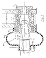
- Such a joint may, for example, be a universal joint or, as in the present case, a ball joint 84 ( FIG. 7 ).
- the pivot has a race 86 with a spherical bearing 88 therein.
- a rod 90 from the mounting member slides axially in a central hole 92 in the spherical bearing.
- a rubber boot 94 may be used to retain lubricant protect against contamination. The rod thus swivels and slides to varying positions 96 as the arm pivot moves, imparting motion to the pivot end of the mounting member 18 ( FIGS. 1-2 ).
- the other end of the mounting member is connected to a swivel joint 98 mounted to the support body 14 by way of a post 100 extending through a hole 102 in the body ( FIG. 3 ) and supported by bearings (not shown) in the body.
- a yoke 104 affixed to the post has a transverse pin 106 affixed in the yoke.
- An extension 108 from the mounting member is supported through additional bearings (not shown) by the transverse pin, allowing the mounting member to swivel at the swivel joint while being moved angularly by the ball joint.
- the mounting member is aligned for the gun to effect the spray stream in a median direction generally parallel to each gear axis.
- the gun is moved angularly in a figure eight motion upon driving of the gear assembly by the drive system such that the deposit on the substrate travels in a figure eight configuration 110 ( FIGS. 1 & 8 ) which also show traversing).
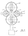
- Each of a pair of larger gears 109 is meshed alternately with each of a pair of smaller gears 113 with a gear ratio of 2:1.
- a truss 115 is formed of four orthogonal arms, each arm having a slot 117 therein.
- a pin 119 off center in each gear slides in a corresponding slot so that that an extension 121 of one arm moves in a figure eight when the gears are rotated.
- a mounting member 18' on the extension holds a thermal spray gun (not shown).
- FIG. 8 actually is a computer simulation of the motion of the arm pivot 74.
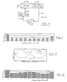
- FIG. 10 shows the velocity profile (velocity vs.
- FIG. 11 shows resulting variations in thickness of a coating deposit along the figure eight configuration, using an HVOF spray gun with powder and spray parameters set forth above.
- the thickness varies from about 6 to 18 (arbitrary units) or by a factor of 3, representing a comparable variation in velocity.
- hot spots were observed for the thicker parts of the deposit at the distal ends of the figure eight.
- This variation in velocity is compensated with a drive system engaged with the input member to provide an input drive with varying speed so as to reduce the non-uniformity of the velocity. It is particularly desirable, when practical, to effect higher velocity in the distal sections of the figure eight to compensate for the tendency otherwise for thicker coating at the edges during a traverse.
- the drive system further comprises a motor control 112 ( FIG. 12 ) connected to operate the motor 52 at a varying speed so as to reduce the non-uniformity of the velocity along the figure eight configuration.
- the motor such as an Electro-Craft AC motor model Y-1002 from has a built-in positional feedback detector 114 that sends a position signal 116 on a line to a programmable logic controller (PLC) 118 such as a model DDM-017 from Alan Bradley.
- PLC programmable logic controller
- This provides a velocity command 120 to an amplifier 122 which converts it to an AC driving voltage 124 to the motor 52, the speed being controlled by variable AC pulses.
- Programming of the controller is achieved according to manufacturer's instructions except that adjustment may be required to compensate for a timing lag so that the instructions lead in proportion to speed. This adjustment may be effected with simple experimentation.
- the speed variation will follow the velocity profile of the mechanism ( FIG. 10 ) inversely, the speed usually being slower while the deposit travels along the distal sections and higher while the deposit travels along the connecting sections.
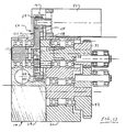
- compensation for the non-uniform velocity may be made mechanically with the linkage 54, such as with an offset cam and follower system 126 ( FIG. 13 ) for the linkage between the motor 52 and the input member (e.g. first axle 38 ).
- the motor drives a driver element in the form of a wheel 128 by a proportionate drive, for example by a gear 58 on the motor shaft engaging gear teeth 130 on the driver wheel.
- This gear ratio may be the same as for the system of FIG. 3 , e.g. 5:1.
- the driver wheel has a driver axle 132 mounted on a pair of bearings 133 in the support body 14, this axle being parallel to and offset from the first axle 38 (above or below in FIG. 13 ).
- the driver wheel has a face 134 which in the present case is a recess in the wheel.
- the face has a radial slot 136 therein.
- a follower element in the form of a wheel 138 is attached by screws 139 to a follower axle which is (or is affixed to) the first axle 38, and the follower element is adjacent to the driver wheel.
- the follower wheel has a follower pin 142 extending therefrom.
- the pin is parallel to the axles and spaced from the follower wheel axle, and preferably is on a bearing (not shown).
- the pin extends into the slot so as to ride therein, the pin preferably having a diameter only slightly smaller than the slot width so as to have a sliding fit.
- the outside of the pin in the slot advantageously is made of a low friction material such as a Delrin plastic.
- Rotation of the driver wheel at constant speed by the motor causes the follower wheel, and correspondingly the first and second gears, to rotate at a varying speed 144 as illustrated in FIG. 14 .
- Other components shown in FIG. 13 are the same as in FIG. 3 .
- Either or both of the driver element and the follower element need not be wheels, and alternatively may be in the form of an arm or a wheel segment or the like, with the respective slot and pin therein.
- the follower axle and the first (or second) axle (or gear) may be connected indirectly by further gearing for ratioed driving of the first (or second) gear.
- the resulting velocity profile 146 ( FIG. 14 ) of the arm pivot, and the corresponding thickness profile of the deposit along the figure eight configuration ( FIG. 15 ), are significantly improved.
- the thickness in this case varies from about 13 to 24 (arbitrary units or by a factor of 1.8, representing a comparable variation in velocity of the spray deposit. This is a reduction of 0.8 or about 27% from the original factor of 3. Hot spots in the deposit, as mentioned above without use of the driver and follower, were not seen in this case.
- the non-uniformity measured as a difference between maximum velocity and minimum velocity, should be reduced by at least 20% by the varying speed of the input drive.
- the present invention should effect a coating of substantially uniform thickness on the substrate wherein variations in the thickness is less than a factor of two.
- the mechanism is intended for mounting onto a traversing device ( FIG. 1 ) so as to traverse the mechanism and thereby the figure eight configuration of the deposit on the substrate to achieve a relatively uniform coating across the substrate.
- the traverse should be in a direction approximately perpendicular to the long axis 148 ( FIG. 5 ) of the figure eight, i.e. within about 30° of perpendicular (the long axis being drawn from the distal tips 150,152, not necessarily through the crossover 154).
- the direction need not be exactly perpendicular but generally should be within a range of about 30° from perpendicular.
- the traverse preferably is a distance D of between 2% and 10% of the length L' of the figure eight configuration, for each full circuit of the spray deposit over the figure eight.
- toothed gears are preferred as being robust for the embodiments described herein, alternative systems may use friction drives, pulleys or chains.
- the linkage may use bevel gears and/or worm gears as may be suitable for the selected motor.
Landscapes
- Nozzles (AREA)
- Spray Control Apparatus (AREA)
- Transmission Devices (AREA)
- Coating By Spraying Or Casting (AREA)
Claims (25)
- Vorrichtung zum Bewegen eines Spritzstrahles aus einer Pistole zum thermischen Spritzen über ein Substrat, umfassend:einen Trägerkörper;einen an dem Körper befestigten Mechanismus, wobei der Mechanismus eine Montageeinrichtung für eine Pistole zum thermischen Spritzen daran aufweist, die einen Spritzstrahl bewirkt, um eine Ablagerung auf einem Substrat zu erzeugen, wobei der Mechanismus dazu dient, an der Pistole und dadurch an dem Spritzstrahl eine Bewegung zu bewirken, sodass die Ablagerung in einem Ablagerungsmuster verläuft, wobei der Mechanismus ein Eingangselement aufweist, das für einen Eingangsantrieb zum Betätigen des Mechanismus aufnahmebereit ist, wobei der Mechanismus derart ist, dass, wenn er von einem Eingangsantrieb mit konstanter Drehzahl angetrieben wird, die Ablagerung entlang der Konfiguration mit einer eine Ungleichmäßigkeit aufweisenden Geschwindigkeit verläuft;dadurch gekennzeichnet, dass der Mechanismus dazu dient, eine achtförmige Bewegung der Pistole und dadurch des Spritzstrahles zu bewirken, und dass ein Antriebssystem mit dem Eingangselement in Eingriff steht, um einem Eingangsantrieb eine variierende Drehzahl zu verleihen und somit die Ungleichmäßigkeit der Geschwindigkeit zu verringern, sodass, wenn die Pistole zum thermischen Spritzen an dem Mechanismus montiert ist und der Trägerkörper auf einer Verfahreinrichtung, die den Mechanismus und dadurch die Pistole zum thermischen Spritzen verfährt, befestigt ist, das Ablagerungsmuster längs dem Substrat verfahren wird, um auf dem Substrat eine Beschichtung mit im Wesentlichen gleichmäßiger Dicke zu bewirken.
- Vorrichtung nach Anspruch 1,
wobei die Ungleichmäßigkeit, die als eine Differenz zwischen einer maximalen Geschwindigkeit und einer minimalen Geschwindigkeit gemessen wird, durch die variierende Drehzahl des Eingangsantriebs um zumindest 20 % reduziert ist. - Vorrichtung nach Anspruch 1,
wobei die Acht ein Verhältnis von Länge zu Breite zwischen etwa 1,5 und 5 aufweist. - Vorrichtung nach Anspruch 1,
wobei das Antriebssystem einen Motor und ein Gestänge, das zwischen den Motor und das Eingangselement geschaltet ist, umfasst. - Vorrichtung nach Anspruch 4,
wobei das Gestänge einen Proportionalantrieb zwischen dem Motor und dem Eingangselement umfasst, und das Antriebssystem ferner eine Motorsteuereinrichtung umfasst, die angeschlossen ist, um den Motor mit einer variierenden Drehzahl zu betreiben und somit die Ungleichmäßigkeit der Geschwindigkeit längs der achtförmigen Konfiguration zu reduzieren. - Vorrichtung nach Anspruch 5,
wobei die achtförmige Konfiguration aus einem Paar distalen Abschnitten und einem Paar Verbindungsabschnitten dazwischen gebildet ist, wobei die Geschwindigkeit in den distalen Abschnitten kleiner und in den Verbindungsabschnitten größer ist, und der Motor mit niedrigerer Drehzahl betrieben wird, während die Ablagerung längs den distalen Abschnitten verläuft, und mit höherer Drehzahl, während die Ablagerung längs den Verbindungsabschnitten verläuft. - Vorrichtung nach Anspruch 4, wobei der Mechanismus umfasst:einen Zahnradabschnitt, der ein erstes Zahnrad mit einer ersten Achse umfasst, die durch den Körper festgehalten ist, und ein zweites Zahnrad mit einer zweiten Achse, die durch den Körper festgehalten ist, wobei das erste Zahnrad und das zweite Zahnrad jeweils eine erste Zahnradachse und eine zweite Zahnradachse aufweisen, die parallel liegen, wobei das erste Zahnrad und das zweite Zahnrad mit einer ausgewählten Zahnradausrichtung in Eingriff stehen und ein ausgewähltes Übersetzungsverhältnis aufweisen, und das erste Zahnrad oder das zweite Zahnrad mit dem Eingangselement gekoppelt ist, so dass es von dem Antriebssystem angetrieben wird;einen Armabschnitt, der einen ersten Stift umfasst, der durch das erste Zahnrad auf einer Stiftachse festgehalten ist, die in einem ersten Radius von der ersten Zahnradachse angeordnet ist, einen zweiten Stift, der durch das zweite Zahnrad auf einer zweiten Stiftachse festgehalten ist, die in einem zweiten Radius von der zweiten Zahnradachse angeordnet ist, einen ersten Arm, der durch den ersten Stift festgehalten ist, und einen zweiten Arm, der durch den zweiten Stift festgehalten ist, wobei der erste Stift eine Achse für den ersten Arm ist, der zweite Stift eine Achse für den zweiten Arm ist, der erste Arm und der zweite Arm mit einem Armdrehzapfen verbunden sind, der eine Drehzapfenachse aufweist, die jeweils mit einer ersten Armlänge von der ersten Stiftachse bzw. einer zweiten Armlänge von der zweiten Stiftachse beabstandet ist, und das Übersetzungsverhältnis, die Zahnradausrichtung, der erste Radius, der zweite Radius, die erste Armlänge und die zweite Armlänge zusammenwirkend gewählt sind, um die Drehzapfenachse in einer achtförmigen Bewegung zu bewegen; undeinen Montageabschnitt, der eine Verbindungseinrichtung umfasst, die an dem Armdrehzapfen oder an dem ersten Arm oder dem zweiten Arm an einer Stelle angebracht ist, die von jedem Stift beabstandet ist, und ein Montageelement umfasst, das mit der Verbindungseinrichtung in Eingriff steht, wobei das Montageelement die Montageeinrichtung für die Pistole zum thermischen Spritzen umfasst, und das Montageelement ausgerichtet ist, damit die Pistole den Spritzstrahl in einer mittleren Richtung im Allgemeinen parallel zu jeder Zahnradachse bewirkt, wodurch die Pistole bei Drehung der Zahnradanordnung durch das Antriebssystem in der achtförmigen Bewegung bewegt wird, sodass die Ablagerung auf dem Substrat in der achtförmigen Konfiguration verläuft.
- Vorrichtung nach Anspruch 7,
wobei die Verbindungseinrichtung ein flexibles Gelenk umfasst, wobei der Montageabschnitt ferner ein Drehgelenk umfasst, das an dem Körper an einer von jedem Arm beabstandeten Position in einer Richtung parallel zu jeder Zahnradachse montiert ist, und das Montageelement zwischen das flexible Gelenk und das Drehgelenk geschaltet ist, wodurch die achtförmige Bewegung eine winklige achtförmige Bewegung der Pistole und dadurch des Spritzstrahles ist. - Vorrichtung nach Anspruch 8,
wobei das flexible Gelenk an dem Armdrehzapfen angebracht ist. - Vorrichtung nach Anspruch 9,
wobei das Übersetzungsverhältnis 2:1 beträgt, und die Zahnradausrichtung derart ist, dass sich der erste Stift im Wesentlichen dann am nächsten bei dem zweiten Zahnrad befindet, wenn sich der zweite Stift am nächsten bei dem ersten Zahnrad befindet. - Vorrichtung nach Anspruch 10,
wobei, relativ zu dem ersten Radius, der in beliebigen Einheiten gleich 1,0 ist, der zweite Radius zwischen etwa 2 und 4 liegt, die erste Armlänge zwischen etwa 10 und 12 liegt und die zweite Armlänge zwischen etwa 9 und 11 liegt. - Vorrichtung nach Anspruch 11,
wobei der zweite Radius etwa 3 beträgt, die erste Armlänge etwa 11,5 beträgt und die zweite Armlänge etwa 10,5 beträgt. - Vorrichtung nach Anspruch 7,
wobei das Eingangselement die erste Achse oder die zweite Achse umfasst. - Vorrichtung nach Anspruch 7,
wobei das Gestänge einen Proportionalantrieb zwischen dem Motor und dem Eingangselement umfasst, und das Antriebssystem ferner eine Motorsteuereinrichtung umfasst, die angeschlossen ist, um den Motor mit einer variierenden Drehzahl zu betreiben und somit die Ungleichmäßigkeit der Geschwindigkeit längs der achtförmigen Konfiguration zu reduzieren. - Vorrichtung nach Anspruch 14,
wobei die achtförmige Konfiguration aus einem Paar distalen Abschnitten und einem Paar Verbindungsabschnitten dazwischen gebildet ist, wobei die Geschwindigkeit in den distalen Abschnitten kleiner und in den Verbindungsabschnitten größer ist, und der Motor mit niedrigerer Drehzahl betrieben wird, während die Ablagerung längs den distalen Abschnitten verläuft, und mit höherer Drehzahl, während die Ablagerung längs den Verbindungsabschnitten verläuft. - Vorrichtung nach Anspruch 14,
wobei der Motor eine Motorachse aufweist, das Eingangselement aus der ersten Achse oder der zweiten Achse besteht, und das Gestänge ein antreibendes Zahnrad umfasst, das koaxial zu der Motorachse befestigt ist, und ein angetriebenes Zahnrad, das koaxial zu dem Eingangselement befestigt ist und mit dem antreibenden Zahnrad kämmt. - Vorrichtung nach Anspruch 7,
wobei der Motor mit konstanter Drehzahl arbeitet und das Gestänge die konstante Drehzahl des Motors in eine variierende Drehzahl an dem Antriebselement umsetzt, um die Ungleichmäßigkeit der Geschwindigkeit der Ablagerung zu reduzieren. - Vorrichtung nach Anspruch 17, wobei das Gestänge umfasst:ein Mitnehmerelement, das derart montiert ist, dass es durch den Motor proportional angetrieben wird, wobei das Mitnehmerelement an einer Mitnehmerachse montiert ist und eine Stirnseite mit einem radialen Schlitz darin aufweist; undein Folgerelement, das an einer Folgerachse montiert ist, welches verbunden ist, um das Eingangselement proportional anzutreiben, wobei die Folgerachse parallel zu der Mitnehmerachse liegt, wobei das Folgerelement einen Folgerstift aufweist, der sich davon beabstandet und parallel zu der Folgerachse erstreckt, wobei das Folgerelement benachbart zu dem Mitnehmerelement liegt, wobei der Folgerstift sich in den Schlitz hinein erstreckt, um darin zu laufen, sodass eine Drehung des Mitnehmerelements mit konstanter Drehzahl durch den Motor bewirkt, dass das Folgerelement und dadurch das Eingangselement mit einer variierenden Drehzahl rotiert.
- Vorrichtung nach Anspruch 18,
wobei das Mitnehmerelement und das Folgerelement jeweils in der Form eines Rades vorliegen. - Vorrichtung nach Anspruch 4,
wobei der Motor mit konstanter Drehzahl arbeitet, und das Gestänge die konstante Drehzahl des Motors in eine variierende Drehzahl an dem Eingangselement umsetzt, um die Ungleichmäßigkeit der Geschwindigkeit der Ablagerung zu reduzieren. - Vorrichtung nach Anspruch 20, wobei das Gestänge umfasst:ein Mitnehmerelement, das derart montiert ist, dass es durch den Motor proportional angetrieben wird, wobei das Mitnehmerelement an einer Mitnehmerachse montiert ist und eine Stirnseite mit einem radialen Schlitz darin aufweist; undein Folgerelement, das an einer Folgerachse montiert ist, welches verbunden ist, um das Eingangselement proportional anzutreiben, wobei die Folgerachse parallel zu der Mitnehmerachse liegt, wobei das Folgerelement einen Folgerstift aufweist, der sich davon beabstandet und parallel zu der Folgerachse erstreckt, wobei das Folgerelement benachbart zu dem Mitnehmerelement liegt, wobei der Folgerstift sich in den Schlitz hinein erstreckt, um darin zu laufen, sodass eine Drehung des Mitnehmerelements mit konstanter Drehzahl durch den Motor bewirkt, dass das Folgerelement und dadurch das Eingangselement mit einer variierenden Drehzahl rotiert.
- Vorrichtung nach Anspruch 21,
wobei das Mitnehmerelement und das Folgerelement jeweils in der Form eines Rades vorliegen. - Vorrichtung nach Anspruch 1,
die ferner eine Verfahreinrichtung mit dem daran montierten Mechanismus umfasst, um den Mechanismus und die achtförmige Konfiguration der Ablagerung zu verfahren. - Vorrichtung nach Anspruch 23,
wobei die Acht eine lange Achse aufweist, und das Verfahren in eine Richtung ungefähr senkrecht zu der langen Achse erfolgt. - Vorrichtung nach Anspruch 24,
wobei das Verfahren über eine Distanz von zwischen 2 % und 10 % der Länge der Acht für jeden vollen Kreis der Acht erfolgt.
Applications Claiming Priority (3)
| Application Number | Priority Date | Filing Date | Title |
|---|---|---|---|
| US09/186,812 US6068201A (en) | 1998-11-05 | 1998-11-05 | Apparatus for moving a thermal spray gun in a figure eight over a substrate |
| PCT/US1999/024105 WO2000027541A1 (en) | 1998-11-05 | 1999-10-14 | Figure eight movement of spray gun |
| US186812 | 2002-06-28 |
Publications (3)
| Publication Number | Publication Date |
|---|---|
| EP1126920A1 EP1126920A1 (de) | 2001-08-29 |
| EP1126920A4 EP1126920A4 (de) | 2008-12-24 |
| EP1126920B1 true EP1126920B1 (de) | 2009-12-09 |
Family
ID=22686375
Family Applications (1)
| Application Number | Title | Priority Date | Filing Date |
|---|---|---|---|
| EP99971741A Expired - Lifetime EP1126920B1 (de) | 1998-11-05 | 1999-10-14 | Bewegung einer sprühpistole gemäss einer achtförmigen bahn |
Country Status (6)
| Country | Link |
|---|---|
| US (1) | US6068201A (de) |
| EP (1) | EP1126920B1 (de) |
| JP (1) | JP4476490B2 (de) |
| CA (1) | CA2343982C (de) |
| DE (1) | DE69941790D1 (de) |
| WO (1) | WO2000027541A1 (de) |
Families Citing this family (10)
| Publication number | Priority date | Publication date | Assignee | Title |
|---|---|---|---|---|
| US6390383B1 (en) * | 2000-07-31 | 2002-05-21 | General Electric Company | Staged feed robotic machine |
| US20030024076A1 (en) * | 2001-08-06 | 2003-02-06 | Xerox Corporation | Replaceable breakaway link |
| NL1022155C2 (nl) * | 2002-12-12 | 2004-06-22 | Otb Group Bv | Werkwijze, alsmede inrichting voor het behandelen van een oppervlak van ten minste één substraat. |
| US8191504B2 (en) | 2006-11-27 | 2012-06-05 | United Technologies Corporation | Coating apparatus and methods |
| US9315888B2 (en) | 2009-09-01 | 2016-04-19 | General Electric Company | Nozzle insert for thermal spray gun apparatus |
| US8237079B2 (en) * | 2009-09-01 | 2012-08-07 | General Electric Company | Adjustable plasma spray gun |
| JP5994049B2 (ja) * | 2012-10-01 | 2016-09-21 | 兵神装備株式会社 | 吐出システム |
| US9272360B2 (en) | 2013-03-12 | 2016-03-01 | General Electric Company | Universal plasma extension gun |
| JP5629028B1 (ja) * | 2014-03-18 | 2014-11-19 | 澤井 豊 | 基本リンク機構及びリンク機構並びに人工動物 |
| JP6572422B2 (ja) * | 2016-06-30 | 2019-09-11 | 井上 賀夫 | 麺撚り綾掛け機構 |
Family Cites Families (13)
| Publication number | Priority date | Publication date | Assignee | Title |
|---|---|---|---|---|
| US4042734A (en) * | 1975-12-02 | 1977-08-16 | The Gyromat Corporation | Method for spray coating |
| US4191791A (en) * | 1976-10-29 | 1980-03-04 | Eutectic Corporation | Method of applying a metal coating to a metal substrate |
| DE2839990C2 (de) * | 1978-09-14 | 1980-05-14 | Audi Nsu Auto Union Ag, 7107 Neckarsulm | Verfahren zum Umschmelzhärten der Oberfläche eines um seine Drehachse rotierenden Werkstücks, welche Oberfläche unterschiedlichen Abstand von der Drehachse hat |
| CH656560A5 (de) * | 1982-03-19 | 1986-07-15 | Castolin Sa | Verfahren zum auftragen einer schutzschicht durch thermisches spritzen. |
| US4614300A (en) * | 1982-04-19 | 1986-09-30 | E. I. Du Pont De Nemours And Company | Computerized spray machine |
| DE3681732D1 (de) * | 1985-11-12 | 1991-10-31 | Osprey Metals Ltd | Herstellen von schichten durch zerstaeuben von fluessigen metallen. |
| US5401539A (en) * | 1985-11-12 | 1995-03-28 | Osprey Metals Limited | Production of metal spray deposits |
| EP0262235B1 (de) * | 1986-09-02 | 1990-08-08 | The Perkin-Elmer Corporation | Vakuumplasmaspritzanlage |
| US4865252A (en) * | 1988-05-11 | 1989-09-12 | The Perkin-Elmer Corporation | High velocity powder thermal spray gun and method |
| GB9008703D0 (en) * | 1990-04-18 | 1990-06-13 | Alcan Int Ltd | Spray deposition of metals |
| US5079043A (en) * | 1990-12-03 | 1992-01-07 | The Perkin-Elmer Corporation | Method for spraying a coating on a disk |
| US5332133A (en) * | 1991-11-01 | 1994-07-26 | Nisshin Flour Milling Co., Ltd. | Powder supplying apparatus and powder spraying apparatus |
| US5795622A (en) * | 1996-12-30 | 1998-08-18 | Owens-Corning Fiberglas Technology, Inc. | Method of rotating or oscillating a flow of granules to form a pattern on an asphalt coated sheet |
-
1998
- 1998-11-05 US US09/186,812 patent/US6068201A/en not_active Expired - Lifetime
-
1999
- 1999-10-14 JP JP2000580758A patent/JP4476490B2/ja not_active Expired - Fee Related
- 1999-10-14 CA CA002343982A patent/CA2343982C/en not_active Expired - Fee Related
- 1999-10-14 WO PCT/US1999/024105 patent/WO2000027541A1/en not_active Ceased
- 1999-10-14 EP EP99971741A patent/EP1126920B1/de not_active Expired - Lifetime
- 1999-10-14 DE DE69941790T patent/DE69941790D1/de not_active Expired - Lifetime
Also Published As
| Publication number | Publication date |
|---|---|
| CA2343982A1 (en) | 2000-05-18 |
| CA2343982C (en) | 2009-12-29 |
| DE69941790D1 (de) | 2010-01-21 |
| WO2000027541A9 (en) | 2000-09-21 |
| EP1126920A1 (de) | 2001-08-29 |
| JP4476490B2 (ja) | 2010-06-09 |
| US6068201A (en) | 2000-05-30 |
| JP2002529229A (ja) | 2002-09-10 |
| EP1126920A4 (de) | 2008-12-24 |
| WO2000027541A1 (en) | 2000-05-18 |
Similar Documents
| Publication | Publication Date | Title |
|---|---|---|
| US6068201A (en) | Apparatus for moving a thermal spray gun in a figure eight over a substrate | |
| CA1334565C (en) | Method and apparatus for coating surfaces of a workpiece | |
| CA2257468C (en) | Method and apparatus for processing fasteners | |
| US5714205A (en) | Method for thermal spray coating interior surfaces using deflecting gas nozzles | |
| JPH0823043B2 (ja) | 金属等の微粒化装置 | |
| CA1078677A (en) | Method and apparatus for spray coating | |
| US20080001005A1 (en) | Apparatus for evenly applying liquids to interior surfaces | |
| US7836847B2 (en) | Multi-station rotation system for use in spray operations | |
| AU6599786A (en) | Production of metal or ceramic deposits | |
| CA3003711C (en) | Wire arc spray swivel head | |
| US7981479B2 (en) | Multi-station rotation system for use in spray operations | |
| US4866241A (en) | Plasma spray apparatus for coating irregular internal surfaces | |
| US4905899A (en) | Atomisation of metals | |
| EP0489328B1 (de) | Verfahren zum Aufsprühen einer Beschichtung auf eine Scheibe | |
| EP0949350B1 (de) | Verfahren zur Entfernung von Unhebenheiten beim hin und her thermischen Spritzen | |
| US4201341A (en) | Device for automatic depositing by welding | |
| EP0444767A2 (de) | Vorrichtung und Verfahren zur Zerstäubung einer Flüssigkeit | |
| WO2017103868A1 (en) | Method for thermal spray deposition of a coating on a surface and apparatus | |
| US6478234B1 (en) | Adjustable injector assembly for melted powder coating deposition | |
| DE19651716C2 (de) | Verfahren und Vorrichtung zum Beschichten eines Substrates | |
| JP2645312B2 (ja) | 双ガンによるサイクロイド吹付方法及び装置 | |
| CN214327846U (zh) | 一种喷涂机 | |
| EP0582946B1 (de) | Farbspritzmaschine mit einem mit variabler Geschwindigkeit rotierenden Arm | |
| US20230014591A1 (en) | Method for thermal spray deposition of a coating on a surface and apparatus | |
| KR100360379B1 (ko) | 광폭합금판재제조용분무주조장치 |
Legal Events
| Date | Code | Title | Description |
|---|---|---|---|
| PUAI | Public reference made under article 153(3) epc to a published international application that has entered the european phase |
Free format text: ORIGINAL CODE: 0009012 |
|
| 17P | Request for examination filed |
Effective date: 20010427 |
|
| AK | Designated contracting states |
Kind code of ref document: A1 Designated state(s): AT BE CH CY DE DK ES FI FR GB GR IE IT LI LU MC NL PT SE |
|
| RBV | Designated contracting states (corrected) |
Designated state(s): CH DE FR LI |
|
| A4 | Supplementary search report drawn up and despatched |
Effective date: 20081125 |
|
| GRAP | Despatch of communication of intention to grant a patent |
Free format text: ORIGINAL CODE: EPIDOSNIGR1 |
|
| GRAS | Grant fee paid |
Free format text: ORIGINAL CODE: EPIDOSNIGR3 |
|
| GRAA | (expected) grant |
Free format text: ORIGINAL CODE: 0009210 |
|
| AK | Designated contracting states |
Kind code of ref document: B1 Designated state(s): CH DE FR LI |
|
| REG | Reference to a national code |
Ref country code: CH Ref legal event code: NV Representative=s name: SULZER MANAGEMENT AG PATENTABTEILUNG/0067 Ref country code: CH Ref legal event code: EP |
|
| REF | Corresponds to: |
Ref document number: 69941790 Country of ref document: DE Date of ref document: 20100121 Kind code of ref document: P |
|
| PLBE | No opposition filed within time limit |
Free format text: ORIGINAL CODE: 0009261 |
|
| STAA | Information on the status of an ep patent application or granted ep patent |
Free format text: STATUS: NO OPPOSITION FILED WITHIN TIME LIMIT |
|
| 26N | No opposition filed |
Effective date: 20100910 |
|
| PGFP | Annual fee paid to national office [announced via postgrant information from national office to epo] |
Ref country code: CH Payment date: 20131021 Year of fee payment: 15 Ref country code: DE Payment date: 20131021 Year of fee payment: 15 Ref country code: FR Payment date: 20131022 Year of fee payment: 15 |
|
| REG | Reference to a national code |
Ref country code: CH Ref legal event code: NV Representative=s name: INTELLECTUAL PROPERTY SERVICES GMBH, CH |
|
| REG | Reference to a national code |
Ref country code: DE Ref legal event code: R119 Ref document number: 69941790 Country of ref document: DE |
|
| REG | Reference to a national code |
Ref country code: CH Ref legal event code: PL |
|
| PG25 | Lapsed in a contracting state [announced via postgrant information from national office to epo] |
Ref country code: CH Free format text: LAPSE BECAUSE OF NON-PAYMENT OF DUE FEES Effective date: 20141031 Ref country code: LI Free format text: LAPSE BECAUSE OF NON-PAYMENT OF DUE FEES Effective date: 20141031 Ref country code: DE Free format text: LAPSE BECAUSE OF NON-PAYMENT OF DUE FEES Effective date: 20150501 |
|
| REG | Reference to a national code |
Ref country code: FR Ref legal event code: ST Effective date: 20150630 |
|
| PG25 | Lapsed in a contracting state [announced via postgrant information from national office to epo] |
Ref country code: FR Free format text: LAPSE BECAUSE OF NON-PAYMENT OF DUE FEES Effective date: 20141031 |