EP1127012B1 - Fixation irreversible d'une capsule sur une tete de recipient autorisant une rotation limitee de ladite capsule sur ladite tete - Google Patents
Fixation irreversible d'une capsule sur une tete de recipient autorisant une rotation limitee de ladite capsule sur ladite tete Download PDFInfo
- Publication number
- EP1127012B1 EP1127012B1 EP99950826A EP99950826A EP1127012B1 EP 1127012 B1 EP1127012 B1 EP 1127012B1 EP 99950826 A EP99950826 A EP 99950826A EP 99950826 A EP99950826 A EP 99950826A EP 1127012 B1 EP1127012 B1 EP 1127012B1
- Authority
- EP
- European Patent Office
- Prior art keywords
- head
- overcap
- assembly
- neck
- base
- Prior art date
- Legal status (The legal status is an assumption and is not a legal conclusion. Google has not performed a legal analysis and makes no representation as to the accuracy of the status listed.)
- Expired - Lifetime
Links
- 230000002427 irreversible effect Effects 0.000 title description 11
- 239000004033 plastic Substances 0.000 claims description 17
- 229920003023 plastic Polymers 0.000 claims description 17
- 230000000903 blocking effect Effects 0.000 claims description 16
- 238000009826 distribution Methods 0.000 claims description 10
- 230000000295 complement effect Effects 0.000 claims description 8
- 235000011837 pasties Nutrition 0.000 claims description 4
- 239000000463 material Substances 0.000 claims description 3
- 230000008719 thickening Effects 0.000 claims 2
- 241000826860 Trapezium Species 0.000 claims 1
- 238000006073 displacement reaction Methods 0.000 abstract description 3
- 229910052751 metal Inorganic materials 0.000 description 19
- 239000002184 metal Substances 0.000 description 19
- 239000002775 capsule Substances 0.000 description 15
- 239000003292 glue Substances 0.000 description 10
- 239000011324 bead Substances 0.000 description 8
- 230000000694 effects Effects 0.000 description 8
- 238000004873 anchoring Methods 0.000 description 7
- 230000002093 peripheral effect Effects 0.000 description 7
- 238000004519 manufacturing process Methods 0.000 description 6
- 238000002347 injection Methods 0.000 description 4
- 239000007924 injection Substances 0.000 description 4
- 238000007789 sealing Methods 0.000 description 4
- 229920001651 Cyanoacrylate Polymers 0.000 description 3
- MWCLLHOVUTZFKS-UHFFFAOYSA-N Methyl cyanoacrylate Chemical compound COC(=O)C(=C)C#N MWCLLHOVUTZFKS-UHFFFAOYSA-N 0.000 description 3
- 239000012528 membrane Substances 0.000 description 3
- 230000003014 reinforcing effect Effects 0.000 description 3
- 239000004576 sand Substances 0.000 description 3
- 239000012815 thermoplastic material Substances 0.000 description 3
- 239000004743 Polypropylene Substances 0.000 description 2
- 206010067171 Regurgitation Diseases 0.000 description 2
- 230000001154 acute effect Effects 0.000 description 2
- 239000000853 adhesive Substances 0.000 description 2
- 230000001070 adhesive effect Effects 0.000 description 2
- 239000002537 cosmetic Substances 0.000 description 2
- 230000007423 decrease Effects 0.000 description 2
- 230000002349 favourable effect Effects 0.000 description 2
- 230000014759 maintenance of location Effects 0.000 description 2
- -1 polypropylene Polymers 0.000 description 2
- 229920001155 polypropylene Polymers 0.000 description 2
- 230000000475 sunscreen effect Effects 0.000 description 2
- 239000000516 sunscreening agent Substances 0.000 description 2
- 229910000838 Al alloy Inorganic materials 0.000 description 1
- 239000004830 Super Glue Substances 0.000 description 1
- 238000013459 approach Methods 0.000 description 1
- 238000004140 cleaning Methods 0.000 description 1
- 238000010276 construction Methods 0.000 description 1
- 239000006071 cream Substances 0.000 description 1
- 239000000428 dust Substances 0.000 description 1
- 239000000975 dye Substances 0.000 description 1
- 230000008014 freezing Effects 0.000 description 1
- 238000007710 freezing Methods 0.000 description 1
- 229920001903 high density polyethylene Polymers 0.000 description 1
- 239000004700 high-density polyethylene Substances 0.000 description 1
- 239000012535 impurity Substances 0.000 description 1
- 238000003780 insertion Methods 0.000 description 1
- 230000037431 insertion Effects 0.000 description 1
- 230000009191 jumping Effects 0.000 description 1
- 239000007788 liquid Substances 0.000 description 1
- 238000000034 method Methods 0.000 description 1
- 238000002156 mixing Methods 0.000 description 1
- 238000000465 moulding Methods 0.000 description 1
- 239000000825 pharmaceutical preparation Substances 0.000 description 1
- 229940127557 pharmaceutical product Drugs 0.000 description 1
- 238000003825 pressing Methods 0.000 description 1
- 230000000750 progressive effect Effects 0.000 description 1
- 230000003252 repetitive effect Effects 0.000 description 1
- 230000000284 resting effect Effects 0.000 description 1
- 238000007493 shaping process Methods 0.000 description 1
- 230000035939 shock Effects 0.000 description 1
- 239000000243 solution Substances 0.000 description 1
- 238000003756 stirring Methods 0.000 description 1
- 230000000472 traumatic effect Effects 0.000 description 1
- 230000002747 voluntary effect Effects 0.000 description 1
Images


Classifications
-
- B—PERFORMING OPERATIONS; TRANSPORTING
- B65—CONVEYING; PACKING; STORING; HANDLING THIN OR FILAMENTARY MATERIAL
- B65D—CONTAINERS FOR STORAGE OR TRANSPORT OF ARTICLES OR MATERIALS, e.g. BAGS, BARRELS, BOTTLES, BOXES, CANS, CARTONS, CRATES, DRUMS, JARS, TANKS, HOPPERS, FORWARDING CONTAINERS; ACCESSORIES, CLOSURES, OR FITTINGS THEREFOR; PACKAGING ELEMENTS; PACKAGES
- B65D47/00—Closures with filling and discharging, or with discharging, devices
- B65D47/04—Closures with discharging devices other than pumps
- B65D47/20—Closures with discharging devices other than pumps comprising hand-operated members for controlling discharge
- B65D47/24—Closures with discharging devices other than pumps comprising hand-operated members for controlling discharge with poppet valves or lift valves, i.e. valves opening or closing a passageway by a relative motion substantially perpendicular to the plane of the seat
- B65D47/241—Closures with discharging devices other than pumps comprising hand-operated members for controlling discharge with poppet valves or lift valves, i.e. valves opening or closing a passageway by a relative motion substantially perpendicular to the plane of the seat the valve being opened or closed by actuating a cap-like element
- B65D47/242—Closures with discharging devices other than pumps comprising hand-operated members for controlling discharge with poppet valves or lift valves, i.e. valves opening or closing a passageway by a relative motion substantially perpendicular to the plane of the seat the valve being opened or closed by actuating a cap-like element moving helically
Definitions
- the invention relates to a system for fixing a capsule to a head. container fitted with a neck surrounding a dispensing orifice.
- This system allows irreversible fixation in the sense that said capsule cannot be detached from the whole without the implementation of significant voluntary efforts likely to at least partially damage the head and / or the capsule. But this fixation is not a total immobilization: once fixed, the capsule can still perform a circular or helical movement of limited amplitude relative to the axis of the neck of the head.
- US patent A-5,199,605 from the applicant describes a distributor of creamy to pasty products having a rigid head fixed on a body or a skirt and a hood.
- the following description contains the references relating to the figures of US - A- 5,199,605.
- the head (1) and the cover (2) comprise complementary screwing means (9 and 19) allowing, by rotation relative, to raise or lower the hood relative to the head.
- the hood carries a central opening (14) and the head has an upper end in form of cylindrical neck (5) for the passage of the product as well as a shutter (3) carried by lugs (4) fixed on the internal wall of the neck. The shutter closes the central opening of the cover when this cover is in the low position.
- the rotation is limited on the one hand by the end of the thread at the end of screwing and on the other hand, as regards the unscrewing, by studs (24) which have been placed on the shoulder (11) of the dispenser and cooperate with the ends (26 and 25) axial reinforcing ribs (260 and 250) of the skirt (16) of the cover.
- the ends (25) and (26) have a different shape.
- the end (25), small but rigid, abuts against a stud (24), which contributes to blocking at the end of screwing and cleaning the end of the net.
- the end (26) is a flexible blade circumferentially which, blocked by the top (240) of a stud (24) then suddenly released, vibrates and acts as a horn at the end of unscrewing.
- the means of blocking employed, in particular because of their size and the low rigidity of the whole, are only effective if the efforts involved are weak. Thanks to the audible warning, the user decreases then stops its effort when the capsule is near a stop.
- the realization of the previous distributor is delicate, mainly because molding of the central part of the head, namely the shutter held in place end of its legs fixed on the internal wall of the neck.
- the tool is complex, especially to make the arms that hold the shutter: these should be as thin as possible - to let the product - and therefore cannot be used as supply channels plastic from a central injection point. It takes in this case make a peripheral injection in several point of the wall of the neck, which not be as fine as you would like.
- EP 0 633 197 describes the whole of a head and a cover, the head having an open end intended to be fixed on the end open container or flexible tube.
- the head has a neck cylindrical and a shoulder which extends from said open end to said neck and the cylindrical neck is provided with at least one helical screw thread.
- the hood has a cylindrical skirt provided on its inner wall with a net complementary to that of the bottleneck.
- the cover carries at least one axial blade (12) radially flexible and circumferentially rigid, one end of said blade being free, the other end being fixed to the cover at a distance from the axis slightly greater than the outside radius of the neck.
- the base of the neck is provided with a profiled portion (14) serving as an opening stop and with a profiled portion (15) serving as a closing stop.
- the opening stop (14) has a first wall which gradually deviates from the cylindrical wall of said neck, so that when the cover is screwed on the head for mounting of the assembly, the free end of the axial blade (12) comes into contact with the first wall and that the axial blade, the free end of which is imposed a radial movement, elastically deforms then, after crossing the opening stop (14), is robotized towards the cylindrical wall of the neck in a space between said opening (14) and closing (15) stops. Its movement is then limited by the blocking walls of said stops.
- the preamble of claim 1 is based on this state of the art.
- the thick and heavy head makes the tube difficult to handle, which is not not appreciated by the user of the container.
- the size of a anti-unscrewing attachment and limited rotation such as one or other of the prior art is such that one cannot envisage equipping the head with other means capable of performing other functions.
- the plaintiff therefore sought to develop a head + assembly lightweight, easy-to-inject, space-saving capsule in which the capsule is fixed on the head irreversibly in the axial direction and to which we can impose a limited rotation, that is to say by ensuring the locking of the capsule as much for screwing as for unscrewing in well defined positions.
- No only the lightness and small size of this fastening system must improve the comfort of use of the containers of the prior art but still they must allow, by the addition of elements fulfilling additional functions, to create new containers belonging to more demanding areas of use, particularly with regard to the tightness of the closure.
- Figure 1 shows schematically the different fixing means. It shows in top view of a head surmounting a cylindrical wall (50) provided with these fastening means (11, 12, 15) cooperating with those (33 and 34) of the cover, the other parts of said cover not being shown.
- the subject of the invention is the assembly of a container head and a cover, said head having an open end intended to be fixed on the end open container or flexible tube with a cylindrical neck (20) and a shoulder (3) extending from said open end to the base (10) of the neck, where the cylindrical neck is provided with at least one screw thread (21) helical pitch P, and where the cover has a cylindrical skirt (35) provided on its inner wall of a screwing means (36) complementary to that of the neck.
- the cover has a top wall (46) on which is fixed at least one axial blade (33) radially flexible and circumferentially rigid. The other end of this flexible blade is free. The blade is placed at a distance of the axis of the cover slightly greater than the external radius of the neck.
- the base the neck is provided with at least one opening stop (12), of position angular ⁇ , and at least at least one closing stop (11), position angutary ⁇ .
- Said opening stop has a first wall (14) which progressively deviates from the cylindrical wall of said neck, so that when the cover is screwed on the head for mounting of the assembly, the free end of the axial blade (33) comes into contact with the first wall (14) of the opening stop (12) and that the axial blade (33), whose free end is imposed a radial movement, is deformed elastically.
- the flexible blade (33) folds down towards the wall of the neck in a space between the said opening and closing stops, its movement then being limited by the blocking walls (16 and 17) of the stops (11 and 12).
- the stop of closure (11) at a lower height than that of the opening stop (12) the radial movement imposed on the free end of the flexible axial blade (33) is centrifugal and the blocking walls (17 and 16) of the opening stop (12), angular position ⁇ , and of the closing stop (11), of angular position ⁇ , are slightly inclined with respect to the axial diametrical planes of positions respective angular ⁇ and ⁇ and cooperate with the wall (47 or 48) of the blade axial (33) which comes into contact so that the free end of the axial blade (33) is urged to move in a centripetal movement.
- the axial blade (33) is radially flexible in that its free end moves elastically under the effect of a weak force in the radial direction and it is rigid circumferentially in the sense that it takes a very great effort to move this same free end in the orthoradial direction, effort such that it causes irreversible deformation, or even rupture, of said blade.
- the axial blade (33) follows the shape of a portion of a ring, with an opening angle ⁇ and an average radius slightly greater than that of neck. Its orthogonal section is a curvilinear trapezoid, the small base and the large base are arcs of a circle, the large base being located towards inside. The small base and the large base are associated with the walls cylindrical of the blade, the other sides are associated with the thick walls (47 and 48) of said blade.
- the blocking walls of the stops do not do not rest on axial diametrical planes, but are slightly inclined compared to these plans.
- the blocking wall (16) of the stopper makes an angle ( ⁇ / 2- ⁇ 1) with the diametrical axial plane of angular position ⁇ and, as far as relates to the opening stop (12), angular position ⁇ , the wall blocking (17) of the stop makes an angle ( ⁇ / 2- ⁇ 2) with the diametrical axial plane of angular position ⁇ .
- its thick walls (47 and 48) are not orthogonal to the cylindrical walls but each form an angle ( ⁇ 1 and ⁇ 2) with the diametrical axial plane passing through the end considered to be less than the corresponding angle ( ⁇ / 2- ⁇ 1) or ( ⁇ / 2- ⁇ 2), so that that an anchoring occurs by the introduction of one of these thick walls in the dihedral formed by the wall of the neck and the blocking wall of the corresponding stop.
- the difference in height between said opening stops and closure is at least equal to P * (
- the fairly high opening stop is preferably a ratchet tooth having an acute ⁇ 2 angle.
- the closing stop can also be a tooth ratchet oriented in opposite direction with an acute angle ⁇ 1, but, if space allows, an L-shaped section anchor stop is preferred: the blocking wall of the stopper is completed by a wall circumferential which comes to trap the end of the axial blade, the latter being by flexible construction radially to pass over the stop opening during assembly screwing and risk of jumping over the closing stop in the absence of this circumferential wall.
- the circumferential wall increases the friction surface offered to the contact with the axial blade, which improves the brake effect announcing the proximity to the stop, improves retention of the axial blade in contact with said stopper, therefore improves the retention of the cover in the closed position.
- the head and the cover are preferably made of thermoplastic material.
- the blade axial is advantageously molded in the extension of the skirt cylindrical cover.
- This skirt is provided on its internal wall with the means of additional screwing (for example one or more "nut” type threads) that of the neck which includes one or more helical threads (threads of "screw” type).
- the hood skirt must be rigid enough so that the threads of "nut” type do not jump over "screw” type threads. For this purpose, if space allows, the hood skirt is advantageously reinforced by axial radial ribs.
- a slot separates the end of the radial axial rib from that of the axial blade.
- a stud is placed on the shoulder to the same distance from the axis as said rib end and located at an angle ⁇ , more than 10 °, about twenty degrees for example, from the stop opening (in the screwing direction) or the closing stop (in the unscrewing direction).
- the audible alert can indeed be installed as much for the closing only for opening.
- practice has led to the avoidance of too many sound effects for a limited rotation angle, because if they are too close together, they no longer make it possible to locate the alert correctly. So it is preferable to provide only one stop with an alert device.
- a brake effect can be given near it: the user feels a slight resistance which indicates that the hood is coming to a stop soon.
- This effect brake is obtained by performing near the stop in the rotation area limited, a wall which moves away from the cylindrical wall of the neck.
- Figure 1 illustrates a spiral distance with the angle ⁇ made by the tangent axial plane to said wall with the axial plane tangent to the neck. This angle is necessarily small, since the stop must keep a height sufficient radial to maintain its blocking efficiency.
- Each part of the head + cover assembly according to the invention is produced separately, preferably by injecting a thermoplastic material into a mold.
- the head can be welded to the open end of a container or of a tube skirt simultaneously with its shaping (overmolding).
- the assembly is then mounted by screwing the cover onto the head.
- the closing stop being located on the radial extension of the opening stop but less high.
- the rotation limited is then of (2 ⁇ / n) - ⁇ if we put n couples (opening stop, stop of closure) on the shoulder and n axial blades on the hood. So if the axial blade, radially flexible, overlapped a stopper, it is found in a new trapping zone, offset from the previous one by (2 ⁇ / n).
- the cooperation of the n blockings of the blades makes it possible to have stops lower radial height and less bulky blades. But for that the stops remain effective, their blocking wall, portion of a substantially diametral axial plane, has a sufficient extent, which requires, taking into account the necessary clearance between the internal cylindrical wall of the blade and the external cylindrical wall of the neck, a radial height minimum, taking into account the inevitable holidays of a few tenths on the molded convex parts of the stops and the blade. In practice, we aim a radial height of the stop such that the true free stop zone is still equal to the clearance between the internal cylindrical wall of the blade and the external cylindrical wall of the neck.
- the head of the container or tube may not be made of plastic.
- the assembly according to the invention is present in the form of a "base + cover" assembly, the base being a intermediate piece with the elements in its upper part characteristics of the head described in the present invention and in its part lower fixing means on the non-plastic head.
- EXAMPLE 1 "CENTERLOCK" tube (figure 1 and figure 2)
- the shutter 26 5 mm in diameter, is held by oblique arms 27, of rectangular orthogonal section 1.5 * 3, fixed to the internal wall of the neck.
- the difficulties in producing such a head require having a neck wall that is at least 2 mm thick in order to obtain industrially acceptable injection conditions.
- the shoulder 10, flat is provided with three studs 15 serving for the audible warning when unscrewing, offset by 20 ° (in the direction of screwing) relative to the opening stops 12.
- the cover 30 is molded separately; it is made of polypropylene. Its outer skirt 44 has a diameter of 35 mm and a thickness of 1.5 mm. It is also fitted with a 3 mm high sealing skirt 32 , with an external diameter of 14 mm: it is inserted without play inside the internal wall of the neck.
- the cover also has an internal skirt 31 of external diameter ⁇ 22mm, provided with a thread 36 on its internal wall (diameter on thread ⁇ 20), high 14mm, complementary to the thread 21 of the neck.
- Two axial blades 33, 20 mm long, radially flexible and circumferentially rigid, are fixed to the base of the cover 30, attached to the internal skirt 31 over its 14 mm height and extending over 6 mm, 1 mm thick, 5 mm (opening angle: ⁇ 6.5 °).
- Their section is in the shape of a curvilinear trapezoid.
- Two ribs 34 of the same length as the axial blades are arranged radially (radial height: 2.5 mm, thickness 1 mm), attached to the axial blade 33 and reinforcing the internal skirt 21 over its entire height. Their free ends have an axial slot 42 2.5 mm high, freeing a circumferentially flexible end 41 , about 2 mm wide, which, by cooperating with the stud 15 placed on the shoulder 10 at about 20 ° in the direction of screwing, emits a sound vibration warning the user of the proximity of the opening stop 12 .
- the product is dispensed through the central orifice 43 of the cover 30, closed by the central shutter 26 when the cover comes into abutment on the closing stop 11 and released by a descent of the shutter 26 relative to the cover 30 , when the cover comes into abutment on the opening stop 12.
- the axial displacement of the top wall 46 of the cover 30 provided with its central orifice 43 relative to the shutter 26 secured to the head, is due to the helical movement driven by limited rotation of the cover relative to the head.
- the conical shape of the wall of the central shutter 26 makes it possible to regulate the dispensing flow rate by opening more or less the cover 30 , the rotation of which is limited to 112.5 °.
- EXAMPLE 2 Cream distribution tube with central annular tents (fig. 3 and fig. 1)
- the product is not dispensed through a central orifice 43 in the cover, which may or may not be closed by a central cover 26 held by arms 27 which clutter the inside of the neck.
- a circular central wall 37 is isolated from the rest of the top part 46 of the cover 30 ' by one of the annular slots 39 regularly distributed over a diameter 8 mm, 2 mm wide and separated by bridges of long material. In this particular case, they are six in number and do not exceed 1 mm in circumferential length.
- An annular bead 38 in relief inside the cover is attached to the periphery of the circular central wall 37.
- the neck is surmounted by a cylindrical appendage 22 having a top wall 23 which delimits an orifice 25 with a diameter of 4 mm.
- the annular bead 38 at the periphery of the circular central wall 37 comes to bear on the top surface 23 of the neck.
- the diameter of the annular bead 38 is close to 6 mm, its height is of the order of 0.5 mm.
- the cover 30 ' is molded separately; it is made of polypropylene. Its outer skirt 44 is 35 mm in diameter and 1.5 mm thick. It is also provided with a sealing skirt 32 ' which straddles the cylindrical appendage 22 , whatever the position of the cover 30' relative to the head.
- the cover 30 ' also has an internal skirt 31 with an external diameter ⁇ 22mm, provided with a thread 36 (internal diameter on the thread ⁇ 20), 14mm high, complementary to the thread 21' of the neck (single thread of pitch 3 mm).
- Two axial blades 33 20 mm long, radially flexible and circumferentially rigid, are fixed to the base of the cover 30 ', attached to the internal skirt 31 on its 14 mm height and extending over 6 mm, 1 mm thick, wide 5mm (opening angle: ⁇ 6.5 °).
- Their section is in the shape of a curvilinear trapezoid.
- Two ribs 34 of the same length as the axial blades are arranged radially (radial height: 2.5 mm, thickness 1 mm), attached to the axial blades 33 and reinforcing the internal skirt 31 over its entire height. Their free ends have an axial slot 42 of 2.5 mm freeing a circumferentially flexible end 41 , about 2 mm wide, which, by cooperating with the stud 15 placed on the shoulder 10 at about 20 ° in the direction of screwing , emits a sound vibration warning the user of the proximity of the opening stop 12.
- the product is dispensed through the annular slots 39 .
- the passage of the product is closed by the peripheral bead 38 which is supported on the top part 23 of the neck when the cover 30 ' is blocked by the closing stop 11.
- the passage is cleared when the bead 38 moves away from the part top 23 of the neck, when the cover is unscrewed and then comes into abutment on the opening stop 12.
- the overall geometries involved are identical (flexible tubes with skirt 35 mm in diameter). Two pairs of opening / closing stops arranged at 180 ° are used.
- the opening stop 11 is accompanied by an audible alarm device (pad 15 at 20 ° in the direction of screwing).
- the closing stop 12 is an L-shaped anchoring stop.
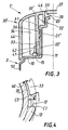
- the radial height H of the stop here of the order of 1 mm, is sufficient to leave a clear stop zone Z at least equal to 0.5 mm, taking account of the clearance J between the internal cylindrical wall 40 of the blade 33 and the external cylindrical wall of the neck 20 (or 20 ′ ), and fillets C1 , C2 of a few tenths of a millimeter on the convex molded parts of the stop 12 and of the blade 33.
- This tube illustrated in FIG. 5, has the irreversible fixing system with limited rotation according to the invention already described in the previous examples, which advantageously complements a dispensing device such as that described in FR-A-2 758 127.
- This device comprises, placed across the passage offered by the neck, supported by the cover 30 ", a valve constituted by a flexible wall 140 perforated by a central hole and a support structure 137.
- the central hole of the flexible wall 140 is closed when the container is at rest, that is to say that the edge of the central hole of the flexible wall 140 is naturally in abutment on the support structure 137 of the valve, in intimate contact over the entire support surface and tight vis-à-vis the product.
- the wall 140 Under the effect of the application of pressure on the flexible wall of the tube, the wall 140 is deformed, which causes the sealed contact between said wall and the support structure 137 to disappear and releases between them an opening for the product release. This gives a selective distribution of the product, which can be adjusted as a function of the pressure on the skirt of the tube.
- the device Without pressure on the tube, the device is effectively sealed. It prevents the product to go out but also any impurity (sand, dust) to return. The product therefore remains free of pollution, which is an important advantage for the consumer.
- the support structure 137 is in the form of a fixed and non-deformable pin while the flexible wall 140 surrounding the orifice is made of an elastomeric thermoplastic material.
- the fixing system according to the invention makes it possible to dispense with the overcap.
- the head is perfectly identical to the head of Example 2, with a 20 'neck surmounted by a cylindrical appendage 22, having a top wall 23 which delimits an orifice 25 with a diameter of 4 mm.
- the valve (wall + support structure) is integral with the cover 30 ".
- the cover 30 apart from its top part supporting said valve, is identical to the cover 30 'of Example 2.
- Its external skirt 44 is 35 mm in diameter and is 1.5 mm thick.
- It is also provided with a sealing skirt (32 ′, fig. 3) which straddles the cylindrical appendage (22, fig. 3) of the neck permanently, regardless of the position of the cover 30 " relative to As in FR-A-2 758 127, the top part of the cover is provided with an elastomeric membrane 140 resting on a central stud 137.
- An annular bead in relief inside the cover is attached to the underside of the central stud 137.
- the bead (38, fig. 3) of the cover comes to bear on the top wall (23, fig. 3) of the neck, when the cover is put in the closed position. Since no product can pass, the elastomeric membrane 140 does not deform, even under the effect of untimely pressure on the skirt of the tube. The product cannot therefore exit and the 30 " cover gives perfect closing security during transport.
- FIG. 5 is a perspective view of the head of the anti-sand anti-leak tube of the example, a part of the cover having been removed in order to visualize the fixing system: a couple of stops for opening stop 12 and closing 11 , the radially flexible blade 33, a stud 15 coming into contact with the circumferentially flexible end 41 of the radial rib 34
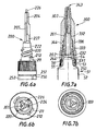
- This tube illustrated in FIGS. 7a and 7b, also has the irreversible fixing system with limited rotation according to the invention, adapted here by using an intermediate plastic insert 200 , illustrated in FIGS. 6a and 6b, between the cannula cover 300 and the metal tube head 51.
- the tube of this example is a tube intended to condition products particularly strong adhesives, such as cyanoacrylate products. Thanks to its cannula-shaped end, it allows you to deposit in one place specifies a controlled amount of product. It is a smaller tube (skirt diameter 13.5 mm) than the previous ones. It illustrates the use of fastening system according to the invention in geometric conditions more severe dimensions. In such conditions, it is not equipped with a audible warning device.
- the cannula cover will preferably have an applicator end rounded, non-traumatic.
- DE 41 26 477 describes a tube for such use, made of aluminum alloy, on the head of which is fixed a plastic cannula, and delivered with a capsule with a needle long enough to allow it to introduced inside a capillary channel, perforate the seal.
- a needle therefore serves, at first use, to perforate the seal and, then, to plug the cannula orifice.
- the fixing system according to the invention irreversible with limited rotation avoids this type of problem, its low dimensions allowing a new arrangement of the participating elements to the controlled distribution of the product.
- the tube according to the invention also uses a needle, but is not equipped with a capsule since it functions like the "centerlock" of Example 1, the cover 30 taking the form of a cannula 300 and the obturator ( 26, fig.2) taking the form of a needle 226 whose length, comparable to that of the cannula, is such that, in the closed position, it slightly exceeds the top of the cannula.
- the packaged product is an adhesive very sensitive to humidity which can only be kept for a long time in a sealed metal tube.
- an intermediate piece 200 is used here which must perforate the cover on first use and then anchor firmly on the metal head to finally play the role of the container head of the previous examples. We will call thereafter "base" this intermediate part with multiple functions.
- the base has four parts: two central (upper and lower) and two peripherals (upper and lower).
- the lower central part of the base 200 is a central duct 201, extending downwards by a tube of approximately 4 mm in diameter, the lower end of which , bevelled, makes it possible to perforate the metal cover 54, after screwing complete of the base 200 on the neck 53 of the metal tube 51. After perforation of the cover, the product packaged in the tube is intended to pass through the interior of this central duct 201.
- the upper central part of the base 200 is the needle 226.
- This needle 226 has a height close to 18mm and a progressive shape in three parts: at the top, it is a cylindrical shutter with a diameter of about 1 mm and ⁇ 1 , 5 mm high, in the middle part, supported by three regularly distributed radial ribs 204 , of thickness ⁇ 0.8 mm, attached to the needle over a height close to 15 mm, in the bottom part, the central part is hollow, in extension of the central duct 201, and the bases 227 of the ribs 204 form a sort of tripod allowing the needle to rest on the peripheral wall of the central duct 201.
- the space between the bases 227 of the ribs offers a wide passage to the product to be dispensed, between the central duct 201 and the internal duct 302 of the cannula 300.
- the upper peripheral part of the base 200 is similar to the cylindrical neck of the previous examples: at the top, the appendix 222, smooth over a height of 3 mm, has a diameter of 4.5 mm.
- the lower part, threaded, has a double helical thread 220 with a pitch close to 6mm over a height of 5 mm.
- the base 210 is provided with two pairs (opening stop 212 / closing stop 211 ), diametrically opposite.
- the stops at the opening 212 are 3 mm high; they are shaped like a ratchet tooth.
- the closing stops 211 are 1 mm high; they are also in the form of a ratchet tooth, oriented in the opposite direction to that of the stops for opening 212.
- the lower peripheral part of the base 200 is a skirt 244 for screwing and anchoring on the head of the metal tube. It is provided in its upper part, on its internal wall, with a helical thread 232 complementary to the screw thread 56 of the metal tube. In its lower part, it carries, still on its internal wall, 12 ratchet teeth 231 elastically deformable in the direction of screwing and intended, by cooperation with the teeth 55, to immobilize the base on the head of the metal tube 51.
- the tube 51 is a metal tube whose skirt 52 has an external diameter of 13.5 mm.
- the metal neck 53 8 mm high, has a thread diameter of approximately 9 mm. It is surmounted by a cover 54 5 mm in diameter.
- Its outer wall is provided in the upper part with a helical thread 56 having a pitch of ⁇ 1.3 mm, complementary to the thread 232 of the base.
- In the lower part it is provided with eight ratchet teeth 55 intended to fix the base at the end of insertion by screwing, after perforation of the cover 54, by blocking the ratchet teeth 231.
- These teeth 231 are oriented in the opposite direction to that of teeth 55. More generally, to have a good anchoring of the base on the head, we will choose a number of teeth 231 and a number of teeth 55 such that their pgcd (greatest common divisor) is greater than or equal to 3.
- the cannula 300 is provided at the bottom with an external skirt 344 threaded on its internal wall and, at the top, with gripping ribs 301 which make it possible to rotate it around the axis of the base. It has an internal conduit 302 intended to conduct the product towards the orifice 343 of distribution. In the lower part, it is a bore 332 which is threaded with a slight tightening around the cylindrical appendage 222. Above, it is the internal conduit 302 proper, whose wall 303 gradually decreases in diameter as and as the product approaches the orifice: this diameter changes from 3mm in the lower part to about 1 mm at the orifice 343.
- the ribs 204 which reinforce the needle 226 have a peripheral wall 205 which conforms, leaving a clearance of a few tenths of a millimeter. the shape of the wall 303 of the internal conduit 302.
- the user deposits a controlled quantity of glue in a specific location. After use, it screws the cannula 300, which has the effect of bringing the end of the needle 226 into the orifice 343.
- the limited rotation allows a axial displacement of the cover / cannula 300 relative to the needle 226, which moves the needle 226 away from or closer to the orifice 343.
- the needle 226 thus acts as a shutter. After closure, the needle has a length such that it protrudes slightly (at least several tenths of a millimeter) from the top of the cannula.
- a limited unscrewing of the cannula 300 makes it possible not only to free the orifice 343 but also to stir the glue which is located near the orifice, thanks to the relative movement of the needle 226 and the ribs 204 relative to the wall 303 of the internal conduit 302.
- the end of the needle 226 is cylindrical, which allows a certain angular movement (therefore a first mixing of the glue by the ribs 204 ) before the release of the capillary channel and the exit of the glue.
- the cannula 300 is produced separately and then assembled by screwing onto the base 200 .
- the blades 333 arrive in the limited rotation zone delimited by the opening stop 212 and the closing stop 211.
- the blades 333 are joined to the outer skirt 344 of the cannula.
- the cannula 300 + base 200 assembly is therefore already equipped with irreversible fixing means in the axial direction allowing limited rotation of the cannula relative to the base.
- the base 200 + cannula 300 assembly is delivered partially screwed onto the head of the metal tube 51 to the conditioner. It is only during its first use that the consumer completes the screwing: it imposes an axial movement of driving the base as well as the anchoring of the base on the tube head after perforation of the cover.
- the ring is replaced by a tamper-evident means 250 attached to the skirt 244 of the base 200.
- This tamper-evident means corresponds to that described in EP 0 475 354: a guarantee strip 252 is connected to the skirt 244 by breakable bridges 251 . It carries internal teeth cooperating with the ratchet teeth 55 carried by the neck 53 of the metal tube. These inner teeth are elastically tiltable in the direction of screwing so as to allow the screwing of the base without breaking the breakable bridges and then to prevent the unscrewing of the base until the bridges are broken.
- the number of internal teeth is preferably chosen such that this and the number of teeth 55 of the metal neck are prime to each other.
- the guarantee strip 252 is not continuous: its two free ends allow it to drain laterally on the first unscrewing. Under these conditions, the user unscrews the base on less than one turn to detach the guarantee strip and then screws fully to perforate the seal.
- the cannula can also be extended by a breakable seal: the area snap around the end of the needle.
Landscapes
- Engineering & Computer Science (AREA)
- Mechanical Engineering (AREA)
- Closures For Containers (AREA)
- Pens And Brushes (AREA)
- Prostheses (AREA)
- Apparatus For Radiation Diagnosis (AREA)
- Electrochromic Elements, Electrophoresis, Or Variable Reflection Or Absorption Elements (AREA)
- Mechanical Pencils And Projecting And Retracting Systems Therefor, And Multi-System Writing Instruments (AREA)
Description
- la butée d'arrêt à l'ouverture 12 est haute de 7mm; elle est en forme de dents à rochet, d'angle d'ouverture γ2=80°;
- la butée d'arrêt à la fermeture 11, haute de 2 mm, se trouve dans le prolongement radial de la butée d'arrêt à l'ouverture, avec une forme en L plus favorable à l'ancrage.
- têtes de récipient à fixation irréversible et rotation limitée allégées;
- têtes de récipient à fixation irréversible et rotation limitée à encombrement réduit;
- têtes de récipient à fixation irréversible et rotation limitée plus simples et plus rapides à fabriquer (cadence de fabrication doublée par rapport à l'art antérieur);
- Régurgitation moins importante du produit à distribuer lorsque que la pression s'annule ( moins de salissures);
- nouvelles fonctions possibles: sécurité au transport sans surcapot des têtes anti-sable; application aux têtes en forme de canule; application sans surbouchage aux produits sensibles à l'humidité ou au contact avec l'air en général; voisinage de l'orifice de distribution propre.
Claims (24)
- Ensemble d'une tête (1, 1') et d'un capot (30, 30', 30", 300), ladite tête ayant une extrémité ouverte (2) destinée à être fixée sur l'extrémité ouverte d'un récipient ou d'un tube souple, possédant un goulot cylindrique (20, 20') et une épaule (3) s'étendant de ladite extrémité ouverte audit goulot, où le goulot cylindrique est muni d'au moins un filet de vissage hélicoïdal (21) de pas P, le capot ayant une jupe cylindrique (31) munie sur sa paroi intérieure d'un filet (36) complémentaire à celui (21) du goulot (20), dans lequel ledit capot porte au moins une lame axiale (33) flexible radialement et rigide circonférentiellement, une extrémité de ladite lame étant libre, l'autre extrémité étant fixée au capot à une distance de l'axe légèrement supérieure au rayon extérieur du goulot, et dans lequel base (10) du goulot est munie d'au moins une butée d'ouverture (12) et d'au moins au moins une butée de fermeture (11) ladite butée d'ouverture ayant une première paroi (14) qui s'écarte progressivement de la paroi cylindrique (26) dudit goulot, de telle sorte que, lorsque le capot (30) est vissé sur la tête pour le montage de l'assemblage, l'extrémité libre de la lame axiale arrive en contact avec la première paroi (14) et que la lame axiale (33), dont l'extrémité fibre se voit imposer un mouvement radial, se déforme élastiquement puis, après franchissement de la butée d'ouverture, se rabat vers la paroi cylindrique du goulot dans un espace compris entre lesdites butées d'ouverture (12) et de fermeture (11), son déplacement étant alors limité par les parois bloquantes (17 et 16) desdites butées (12 et 11), caractérisé en ce que la butée de fermeture (11) a une hauteur plus faible que celle de la butée d'ouverture (12), en ce que la mouvement radial imposé à l'extrémité libre de la lame axiale (33) est en ce que lesdites parois bloquantes (17 et 16) centrifuge et de la butée d'ouverture (12), de position angulaire , et de la butée de fermeture (11), de position angulaire , sont faiblement inclinées par rapport aux plans diamétraux axiaux de positions angulaires respectives et et coopèrent avec la paroi (47 ou 48) de la lame axiale (33) qui arrive à leur contact de telle sorte que l'extrémité libre de la lame axiale (33) est sollicitée à se déplacer suivant un mouvement centripète.
- Ensemble d'une tête (1,1') et d'un capot (30,30',30",300) selon la revendication 1, dans lequel ladite lame axiale (33) épouse la forme d'une portion d'anneau et présente des parois d'épaisseur (47 et 48) qui ne sont pas orthogonales aux parvis cylindriques de ladite lame axiale.
- Ensemble d'une tête (1, 1') et d'un capot (30, 30', 30", 300) selon la revendication 1 ou 2, caractérisé en ce que la lame axiale (33) épouse la forme d'une portion d'anneau, de rayon moyen légèrement supérieur à celui du goulot, la section orthogonale étant un trapèze curviligne, dont la petite base et la grande base sont des arcs de cercle d'angle d'ouverture δ, la grande base étant située vers l'intérieur.
- Ensemble d'une tête (1, 1') et d'un capot (30, 30', 30", 300) ) selon l'une quelconque des revendications 1 à 3, caractérisé en ce que la différence de hauteur entre les butées d'ouverture (12) et de fermeture (11) est au moins égale à P*(|-|-δ)/2Π.
- Ensemble d'une tête (1, 1') et d'un capot (30, 30', 30", 300) selon l'une quelconque des revendications 1 à 4, caractérisé en ce que lesdites butée d'ouverture (12) ou de fermeture (11) sont des dents à rochet ou des ancrages en forme de L.
- Ensemble d'une tête (1, 1') et d'un capot (30, 30', 30", 300) selon l'une quelconque des revendications 1 à 5, caractérisé en ce que la lame axiale (33) est moulée dans le prolongement de la jupe (31) servant au vissage du capot et en ce que cette jupe (31) est renforcée par au moins une nervure axiale (34), orientée radialement, accolée à ladite lame axiale.
- Ensemble d'une tête (1, 1') et d'un capot (30, 30', 30", 300) selon l'une quelconque des revendications 1 à 6, caractérisé en ce que le goulot est muni d'un filet "vis" de vissage hélicoïdal avec un départ de filet droit et en ce que la paroi interne de la jupe (31) de capot est munie d'un filet "écrou" à arrêt de filet droit.
- Ensemble d'une tête (1, 1') et d'un capot (30, 30', 30", 300) selon l'une quelconque des revendications 1 à 7, caractérisé en ce que la nervure axiale (34) a une extrémité inférieure (41), séparée de la lame par une fente (42), flexible circonférentiellement, qui joue le rôle de lame flexible sonore lorsqu'elle arrive en contact avec un plot (15) situé sur l'épaule, à la même distance de l'axe du goulot que l'extrémité inférieure (41) flexible de la nervure axiale (34) et situé à un angle α, de plus de 10 degrés, dans le sens de dévissage de la butée de fermeture (11) ou dans le sens de vissage de la butée d'ouverture (12).
- Ensemble d'une tête (1, 1') et d'un capot (30, 30', 30", 300) selon l'une quelconque des revendications 1 à 8, caractérisé en ce que la butée est munie d'un frein, c'est-à-dire d'une paroi qui s'écarte de la paroi cylindrique du goulot, dans la zone de rotation limitée.
- Ensemble d'une tête (1, 1') et d'un capot (30, 30', 30", 300) selon l'une quelconque des revendications 1 à 9, caractérisé en ce que le goulot est muni de n ensembles de butées, la butée de fermeture étant située dans le prolongement radial de la butée d'ouverture et en ce que le capot est muni de n lames axiales.
- Ensemble d'une tête (1') et d'un capot (30', 30") selon l'une quelconque des revendications 1 à 10, caractérisé en ce que le goulot (20') est muni d'une paroi sommitale (23) qui entoure l'orifice (25) et en ce que ledit capot a une paroi centrale (37), un bourrelet annulaire (38) étant attaché sur sa surface interne, ledit bourrelet venant s'appuyer, en position fermée, sur la surface sommitale (23) du goulot (20').
- Tube muni d'une tête et d'un capot dont le dévissage partiel éloigne le sommet de la capsule par rapport à celui de la tête et libére ainsi un orifice central (43) permettant la distribution du produit, caractérisé en ce qu'il est muni de l'ensemble d'une tête (1) et d'un capot (30) selon l'une quelconque des revendications 1 à 10
- Tube muni d'une tête et d'un capot dont le dévissage partiel éloigne le sommet de la capsule par rapport à celui de la tête, caractérisé en ce qu'il est muni de l'ensemble d'une tête (1') et d'un capot (30', 30") selon la revendication 11.
- Tube distributeur de produits crémeux à pâteux au travers de fentes circulaires centrales caractérisé en ce qu'il est muni de l'ensemble d'une tête (1') et d'un capot (30') selon la revendication 11.
- Tube distributeur de produits crémeux à pâteux, anti-goutte et anti-sable, caractérisé en ce qu'il est muni de l'ensemble d'une tête (1') et d'un capot (30") selon la revendication 11.
- Ensemble d'une tête et d'un capot selon l'une quelconque des revendications 1 à 10 caractérisé en ce que le capot est en forme de canule (300) et en ce que la tête est prolongée par une aiguille (226).
- Ensemble d'une tête métallique (51), d'une embase (200) en matière plastique et d'un capot (300), caractérisé en ce que la tête métallique (51) et l'embase (200) sont munies de moyens (231 et 55) coopérant entre eux pour fixer de façon irréversible l'embase (200) sur la tête métallique (51) et en ce que l'embase (200) et le capot (300) sont munis des moyens selon l'une quelconque des revendications 1 à 11, où l'embase (200) joue le rôle de la tête.
- Ensemble d'une tête métallique (51), d'une embase (200) en matière plastique et d'un capot (300) selon la revendication 17, caractérisé en ce que le capot est en forme de canule (300) et en ce que l'embase (200) est prolongée par une aiguille (226).
- Ensemble d'une tête métallique (51), d'une embase (200) en matière plastique et d'un capot (300) selon la revendication 18, caractérisé en ce que l'aiguille (226) a une longueur telle que, en position fermée, l'aiguille (226) déborde d'au moins plusieurs dixièmes de millimètres du sommet de la canule (300).
- Ensemble d'une tête métallique (51), d'une embase (200) en matière plastique et d'un capot (300) selon la revendication 18, caractérisé en ce que la canule (300) est prolongée par un opercule sécabie en forme de bâtonnet.
- Ensemble d'une tête métallique (51), d'une embase (200) en matière plastique et d'un capot (300) selon l'une quelconque des revendications 17 à 20. caractérisé en ce que la tête métallique possède un goulot (53) dont l'orifice est obturé par un opercule (54) et en ce que l'embase est munie d'un conduit central (201) dont l'extrémité inférieure (202) permet de perforer à la première utilisation l'opercule (54) de la tête métallique (51).
- Ensemble d'une tête métallique (51), d'une embase (200) en matière plastique et d'un capot (300) selon l'une quelconque des revendications 18 à 21, caractérisé en ce que l'embase (200) est munie de moyens d'inviolabilité (250).
- Ensemble d'une tête métallique (51), d'une embase (200) en matière plastique et d'un capot (300) selon l'une quelconque des revendications 18 à 21, caractérisé en ce qu'avant première utilisation, un anneau est interposé entre l'embase (200) et la tête métallique (51).
- Tube distributeur métallique caractérisé en ce qu'il est muni de l'ensemble d'une tête métallique (51), d'une embase (200) en matière plastique et d'un capot (300) selon l'une quelconque des revendications 17 à 23.
Applications Claiming Priority (3)
| Application Number | Priority Date | Filing Date | Title |
|---|---|---|---|
| FR9813962A FR2785261B1 (fr) | 1998-11-03 | 1998-11-03 | Fixation irreversible d'une capsule sur une tete de recipient autorisant une rotation limitee de ladite capsule sur ladite tete |
| FR9813962 | 1998-11-03 | ||
| PCT/FR1999/002593 WO2000026105A1 (fr) | 1998-11-03 | 1999-10-26 | Fixation irreversible d'une capsule sur une tete de recipient autorisant une rotation limitee de ladite capsule sur ladite tete |
Publications (2)
| Publication Number | Publication Date |
|---|---|
| EP1127012A1 EP1127012A1 (fr) | 2001-08-29 |
| EP1127012B1 true EP1127012B1 (fr) | 2003-07-23 |
Family
ID=9532429
Family Applications (1)
| Application Number | Title | Priority Date | Filing Date |
|---|---|---|---|
| EP99950826A Expired - Lifetime EP1127012B1 (fr) | 1998-11-03 | 1999-10-26 | Fixation irreversible d'une capsule sur une tete de recipient autorisant une rotation limitee de ladite capsule sur ladite tete |
Country Status (10)
| Country | Link |
|---|---|
| US (1) | US6669063B1 (fr) |
| EP (1) | EP1127012B1 (fr) |
| AT (1) | ATE245580T1 (fr) |
| AU (1) | AU6345899A (fr) |
| BR (1) | BR9915000A (fr) |
| CA (1) | CA2348712A1 (fr) |
| DE (1) | DE69909815T2 (fr) |
| ES (1) | ES2204162T3 (fr) |
| FR (1) | FR2785261B1 (fr) |
| WO (1) | WO2000026105A1 (fr) |
Families Citing this family (11)
| Publication number | Priority date | Publication date | Assignee | Title |
|---|---|---|---|---|
| US7648051B1 (en) * | 2006-08-09 | 2010-01-19 | Rexam Closures And Containers Inc. | Double shell dispensing closure with a reverse tapered drop lug |
| US7635071B1 (en) | 2006-08-09 | 2009-12-22 | Rexam Closures And Containers Inc. | Double shell dispensing closure with a reverse tapered drop lug |
| US7900789B2 (en) * | 2007-05-30 | 2011-03-08 | Graham Packaging Company, Lp | Non-removable finish and closure system |
| DE102008007306A1 (de) * | 2008-02-02 | 2009-08-06 | Fischbach Kg Kunststoff-Technik | Auspressvorrichtung für plastische Massen |
| US20110226812A1 (en) * | 2010-03-17 | 2011-09-22 | Yonyu Plastics Co., Ltd. | Fluid dispenser device |
| EP2585386B1 (fr) * | 2010-06-23 | 2016-12-14 | Müslüm Yildirim | Récipient distributeur |
| GB201111400D0 (en) * | 2011-07-04 | 2011-08-17 | Obrist Closures Switzerland | A closure |
| CN103781722B (zh) * | 2011-07-15 | 2015-11-25 | Mwv斯莱特斯维尔有限责任公司 | 延迟流动挡板分送闭合件 |
| USD687665S1 (en) | 2012-04-16 | 2013-08-13 | Clay D. Nagel | Water jug with an insulated cover |
| US9815598B2 (en) * | 2013-08-01 | 2017-11-14 | Mars, Incorporated | Container |
| EP3609800B1 (fr) * | 2017-04-14 | 2024-07-10 | Sanford, L.P. | Capuchon anti-obstruction |
Citations (1)
| Publication number | Priority date | Publication date | Assignee | Title |
|---|---|---|---|---|
| EP0633197A1 (fr) * | 1993-07-09 | 1995-01-11 | Cebal S.A. | Ensemble d'un récipient et d'un bouchage se verrouillant ensemble par rotation relative et son utilisation |
Family Cites Families (19)
| Publication number | Priority date | Publication date | Assignee | Title |
|---|---|---|---|---|
| GB520118A (en) * | 1938-11-25 | 1940-04-15 | Hermann Pollard | An improvement in or relating to belt fasteners |
| GB558273A (en) * | 1942-03-27 | 1943-12-30 | Wellcome Found | Improvements in or relating to the manufacture of dibenzyl derivatives |
| US3175741A (en) * | 1964-03-12 | 1965-03-30 | Product Design & Engineering I | Closure and dispensing cap for the neck of a container |
| US3273754A (en) * | 1964-12-28 | 1966-09-20 | Leonard H King | One-piece closure for collapsible containers |
| US4149646A (en) * | 1978-06-21 | 1979-04-17 | Sunbeam Plastics Corporation | Child-resistant locking means for a container |
| FR2600978B1 (fr) * | 1986-05-12 | 1990-06-08 | Astra Plastique | Bouchon distributeur a capuchon tournant pour produits pateux |
| US4817831A (en) * | 1988-03-28 | 1989-04-04 | Theisen G Jerry | Dispensing cap with expandable plug |
| US4964548A (en) * | 1988-04-13 | 1990-10-23 | Mccormick & Company, Inc. | Dispensing closure having an interior sealing sleeve, a threaded sleeve engaging a threaded tube, and stop blocks limiting twisting of the closure cap |
| US5199605A (en) | 1989-01-06 | 1993-04-06 | Cebal | Creamy or pasty product dispenser with a rotationally controlled aperture in the cap and with safety means against uncontrolled opening |
| DE69004182T2 (de) * | 1989-07-28 | 1994-05-26 | Tuboplast Hispania, S.A., Vitoria | Rohrförmiger Behälter mit nichtabnehmbarem Abgabeverschluss. |
| DE4028800A1 (de) | 1990-09-11 | 1992-03-12 | Behringwerke Ag | Gentechnische sialylierung von glykoproteinen |
| ES2037591B1 (es) * | 1991-06-28 | 1994-02-01 | Tuboplast Hispania | Envase tubular con tapon practicable no desmontable, de seguridad. |
| DE4126477C2 (de) | 1991-08-07 | 1996-09-05 | Henkel Kgaa | Tube mit einer von einer Membran verschlossenen Mündungsöffnung |
| US5305932A (en) * | 1993-04-19 | 1994-04-26 | Seda International Plastics | Permanent snap-on, twist-open cap and container |
| FR2708570B1 (fr) * | 1993-08-03 | 1995-10-13 | Rouviere Yves Francois | Buse à obturation interne pour écoulement de produits visqueux ou pâteux expulsés de leur emballage par compression. |
| FR2758127B1 (fr) | 1997-01-08 | 1999-02-12 | Rocher Yves Biolog Vegetale | Dispositif anti-sable d'obturation d'un flacon et ensemble comprenant le dispositif lie au flacon |
| US6062441A (en) * | 1999-07-15 | 2000-05-16 | Rxi Plastics, Inc. | Two-piece dispensing closure |
| US6543650B1 (en) * | 2001-01-25 | 2003-04-08 | Rexam Medical Packaging Inc. | Double shell dispenser |
| FR2857127B1 (fr) | 2003-07-03 | 2005-12-23 | Keosys | Dispositif de communication et d'affichage de donnees numeriques incluant au moins une image, notamment a caractere medical |
-
1998
- 1998-11-03 FR FR9813962A patent/FR2785261B1/fr not_active Expired - Fee Related
-
1999
- 1999-10-26 ES ES99950826T patent/ES2204162T3/es not_active Expired - Lifetime
- 1999-10-26 WO PCT/FR1999/002593 patent/WO2000026105A1/fr not_active Ceased
- 1999-10-26 BR BR9915000-0A patent/BR9915000A/pt not_active IP Right Cessation
- 1999-10-26 EP EP99950826A patent/EP1127012B1/fr not_active Expired - Lifetime
- 1999-10-26 US US09/807,989 patent/US6669063B1/en not_active Expired - Fee Related
- 1999-10-26 CA CA002348712A patent/CA2348712A1/fr not_active Abandoned
- 1999-10-26 AU AU63458/99A patent/AU6345899A/en not_active Abandoned
- 1999-10-26 DE DE69909815T patent/DE69909815T2/de not_active Expired - Fee Related
- 1999-10-26 AT AT99950826T patent/ATE245580T1/de not_active IP Right Cessation
Patent Citations (1)
| Publication number | Priority date | Publication date | Assignee | Title |
|---|---|---|---|---|
| EP0633197A1 (fr) * | 1993-07-09 | 1995-01-11 | Cebal S.A. | Ensemble d'un récipient et d'un bouchage se verrouillant ensemble par rotation relative et son utilisation |
Also Published As
| Publication number | Publication date |
|---|---|
| EP1127012A1 (fr) | 2001-08-29 |
| FR2785261A1 (fr) | 2000-05-05 |
| US6669063B1 (en) | 2003-12-30 |
| DE69909815D1 (de) | 2003-08-28 |
| DE69909815T2 (de) | 2004-06-03 |
| WO2000026105A1 (fr) | 2000-05-11 |
| AU6345899A (en) | 2000-05-22 |
| BR9915000A (pt) | 2001-07-10 |
| ES2204162T3 (es) | 2004-04-16 |
| CA2348712A1 (fr) | 2000-05-11 |
| ATE245580T1 (de) | 2003-08-15 |
| FR2785261B1 (fr) | 2000-12-08 |
Similar Documents
| Publication | Publication Date | Title |
|---|---|---|
| EP0839735B1 (fr) | Capsule articulée à élément de liaison amélioré | |
| EP0655045B1 (fr) | Distributeur a plusieurs compartiments pour le stockage et le melange du contenu | |
| EP0816245B1 (fr) | Tête de distibution d'un produit liquide à consistance visqueuse comportant un organe élastique de fermeture, et ensemble de distribution ainsi équipé | |
| EP2704961B3 (fr) | Bouchon pour un col de récipient | |
| CA1073411A (fr) | Recipient de conditionnement et de distribution comportant au stockage deux compartiments separes | |
| WO1996030273A1 (fr) | Distributeur pour le soutirage d'un produit fluide contenu dans un recipient | |
| EP3603817B1 (fr) | Montage et démontage facilité d'une pompe par rapport au réservoir | |
| EP0951429B1 (fr) | Dispositif de distribution a securite de devissage | |
| EP0912402B1 (fr) | Recipient avec fermeture reutilisable monte d'une seule piece et son procede de fabrication | |
| FR3065156B1 (fr) | Ensemble de conditionnement et de distribution d'un produit fluide bi-composant | |
| FR3065155A1 (fr) | Ensemble de conditionnement et de distribution d'un produit fluide avec reprise d'air | |
| EP1751023B1 (fr) | Distributeur de parfum | |
| EP1127012A1 (fr) | Fixation irreversible d'une capsule sur une tete de recipient autorisant une rotation limitee de ladite capsule sur ladite tete | |
| CH659634A5 (fr) | Ensemble pour le conditionnement et l'application d'une substance de type vernis. | |
| FR2660632A1 (fr) | Dispositif de bouchon non refermable pour distributeur. | |
| FR2565208A1 (fr) | Ensemble verseur et capsule de bouchage inviolable | |
| EP1103478B1 (fr) | Ensemble de conditionnement en plastique à recyclage amélioré | |
| FR2882505A1 (fr) | Tube distributeur de produits cremeux | |
| FR2872687A1 (fr) | Dispositif de conditionnement et d'application d'un produit | |
| FR2935877A1 (fr) | Dispositif d'essorage pour ensemble applicateur pour produit cosmetique liquide, pateux ou en poudre tel que du mascara ou de l'eye-liner | |
| BE897445A (fr) | Flacon equipe d'un capot de bouchage etanche | |
| EP0143704B1 (fr) | Dispositif verseur pour bidon ainsi que les bidons pourvus de ce dispositif | |
| WO2020212663A1 (fr) | Distributeur de produit fluide | |
| FR3096037A1 (fr) | Système de fermeture d’un contenant | |
| FR3052756A1 (fr) | Capsule service avec languette detachable |
Legal Events
| Date | Code | Title | Description |
|---|---|---|---|
| PUAI | Public reference made under article 153(3) epc to a published international application that has entered the european phase |
Free format text: ORIGINAL CODE: 0009012 |
|
| 17P | Request for examination filed |
Effective date: 20010418 |
|
| AK | Designated contracting states |
Kind code of ref document: A1 Designated state(s): AT BE CH CY DE DK ES FI FR GB GR IE IT LI LU MC NL PT SE |
|
| 17Q | First examination report despatched |
Effective date: 20010910 |
|
| RTI1 | Title (correction) |
Free format text: IRREVERSIBLE FIXING OF A CAP ON A CONTAINER HEAD ENABLING A LIMITED ROTATION OF SAID CAP ON SAID HEAD |
|
| GRAH | Despatch of communication of intention to grant a patent |
Free format text: ORIGINAL CODE: EPIDOS IGRA |
|
| GRAH | Despatch of communication of intention to grant a patent |
Free format text: ORIGINAL CODE: EPIDOS IGRA |
|
| RAP1 | Party data changed (applicant data changed or rights of an application transferred) |
Owner name: CEBAL S.A.S. |
|
| GRAA | (expected) grant |
Free format text: ORIGINAL CODE: 0009210 |
|
| AK | Designated contracting states |
Designated state(s): AT BE CH CY DE DK ES FI FR GB GR IE IT LI LU MC NL PT SE |
|
| PG25 | Lapsed in a contracting state [announced via postgrant information from national office to epo] |
Ref country code: NL Free format text: LAPSE BECAUSE OF FAILURE TO SUBMIT A TRANSLATION OF THE DESCRIPTION OR TO PAY THE FEE WITHIN THE PRESCRIBED TIME-LIMIT Effective date: 20030723 Ref country code: IE Free format text: LAPSE BECAUSE OF FAILURE TO SUBMIT A TRANSLATION OF THE DESCRIPTION OR TO PAY THE FEE WITHIN THE PRESCRIBED TIME-LIMIT Effective date: 20030723 Ref country code: FI Free format text: LAPSE BECAUSE OF FAILURE TO SUBMIT A TRANSLATION OF THE DESCRIPTION OR TO PAY THE FEE WITHIN THE PRESCRIBED TIME-LIMIT Effective date: 20030723 |
|
| REG | Reference to a national code |
Ref country code: GB Ref legal event code: FG4D Free format text: NOT ENGLISH |
|
| REG | Reference to a national code |
Ref country code: CH Ref legal event code: EP |
|
| REG | Reference to a national code |
Ref country code: IE Ref legal event code: FG4D Free format text: FRENCH |
|
| REF | Corresponds to: |
Ref document number: 69909815 Country of ref document: DE Date of ref document: 20030828 Kind code of ref document: P |
|
| PGFP | Annual fee paid to national office [announced via postgrant information from national office to epo] |
Ref country code: DE Payment date: 20030918 Year of fee payment: 5 Ref country code: AT Payment date: 20030918 Year of fee payment: 5 |
|
| PGFP | Annual fee paid to national office [announced via postgrant information from national office to epo] |
Ref country code: GB Payment date: 20030922 Year of fee payment: 5 |
|
| PGFP | Annual fee paid to national office [announced via postgrant information from national office to epo] |
Ref country code: FR Payment date: 20031008 Year of fee payment: 5 |
|
| PGFP | Annual fee paid to national office [announced via postgrant information from national office to epo] |
Ref country code: ES Payment date: 20031010 Year of fee payment: 5 |
|
| PG25 | Lapsed in a contracting state [announced via postgrant information from national office to epo] |
Ref country code: SE Free format text: LAPSE BECAUSE OF FAILURE TO SUBMIT A TRANSLATION OF THE DESCRIPTION OR TO PAY THE FEE WITHIN THE PRESCRIBED TIME-LIMIT Effective date: 20031023 Ref country code: GR Free format text: LAPSE BECAUSE OF FAILURE TO SUBMIT A TRANSLATION OF THE DESCRIPTION OR TO PAY THE FEE WITHIN THE PRESCRIBED TIME-LIMIT Effective date: 20031023 Ref country code: DK Free format text: LAPSE BECAUSE OF FAILURE TO SUBMIT A TRANSLATION OF THE DESCRIPTION OR TO PAY THE FEE WITHIN THE PRESCRIBED TIME-LIMIT Effective date: 20031023 |
|
| PG25 | Lapsed in a contracting state [announced via postgrant information from national office to epo] |
Ref country code: LU Free format text: LAPSE BECAUSE OF NON-PAYMENT OF DUE FEES Effective date: 20031026 Ref country code: CY Free format text: LAPSE BECAUSE OF FAILURE TO SUBMIT A TRANSLATION OF THE DESCRIPTION OR TO PAY THE FEE WITHIN THE PRESCRIBED TIME-LIMIT Effective date: 20031026 |
|
| PGFP | Annual fee paid to national office [announced via postgrant information from national office to epo] |
Ref country code: CH Payment date: 20031029 Year of fee payment: 5 |
|
| PG25 | Lapsed in a contracting state [announced via postgrant information from national office to epo] |
Ref country code: MC Free format text: LAPSE BECAUSE OF NON-PAYMENT OF DUE FEES Effective date: 20031031 Ref country code: BE Free format text: LAPSE BECAUSE OF NON-PAYMENT OF DUE FEES Effective date: 20031031 |
|
| REG | Reference to a national code |
Ref country code: CH Ref legal event code: NV Representative=s name: WILLIAM BLANC & CIE CONSEILS EN PROPRIETE INDUSTRI |
|
| NLV1 | Nl: lapsed or annulled due to failure to fulfill the requirements of art. 29p and 29m of the patents act | ||
| GBT | Gb: translation of ep patent filed (gb section 77(6)(a)/1977) |
Effective date: 20031117 |
|
| PG25 | Lapsed in a contracting state [announced via postgrant information from national office to epo] |
Ref country code: PT Free format text: LAPSE BECAUSE OF FAILURE TO SUBMIT A TRANSLATION OF THE DESCRIPTION OR TO PAY THE FEE WITHIN THE PRESCRIBED TIME-LIMIT Effective date: 20031223 |
|
| REG | Reference to a national code |
Ref country code: IE Ref legal event code: FD4D |
|
| REG | Reference to a national code |
Ref country code: ES Ref legal event code: FG2A Ref document number: 2204162 Country of ref document: ES Kind code of ref document: T3 |
|
| BERE | Be: lapsed |
Owner name: *CEBAL S.A.S. Effective date: 20031031 |
|
| PLBE | No opposition filed within time limit |
Free format text: ORIGINAL CODE: 0009261 |
|
| STAA | Information on the status of an ep patent application or granted ep patent |
Free format text: STATUS: NO OPPOSITION FILED WITHIN TIME LIMIT |
|
| 26N | No opposition filed |
Effective date: 20040426 |
|
| PG25 | Lapsed in a contracting state [announced via postgrant information from national office to epo] |
Ref country code: GB Free format text: LAPSE BECAUSE OF NON-PAYMENT OF DUE FEES Effective date: 20041026 Ref country code: AT Free format text: LAPSE BECAUSE OF NON-PAYMENT OF DUE FEES Effective date: 20041026 |
|
| PG25 | Lapsed in a contracting state [announced via postgrant information from national office to epo] |
Ref country code: ES Free format text: LAPSE BECAUSE OF NON-PAYMENT OF DUE FEES Effective date: 20041027 |
|
| PG25 | Lapsed in a contracting state [announced via postgrant information from national office to epo] |
Ref country code: LI Free format text: LAPSE BECAUSE OF NON-PAYMENT OF DUE FEES Effective date: 20041031 Ref country code: CH Free format text: LAPSE BECAUSE OF NON-PAYMENT OF DUE FEES Effective date: 20041031 |
|
| PG25 | Lapsed in a contracting state [announced via postgrant information from national office to epo] |
Ref country code: DE Free format text: LAPSE BECAUSE OF NON-PAYMENT OF DUE FEES Effective date: 20050503 |
|
| GBPC | Gb: european patent ceased through non-payment of renewal fee |
Effective date: 20041026 |
|
| REG | Reference to a national code |
Ref country code: CH Ref legal event code: PL |
|
| PG25 | Lapsed in a contracting state [announced via postgrant information from national office to epo] |
Ref country code: FR Free format text: LAPSE BECAUSE OF NON-PAYMENT OF DUE FEES Effective date: 20050630 |
|
| REG | Reference to a national code |
Ref country code: FR Ref legal event code: ST |
|
| PG25 | Lapsed in a contracting state [announced via postgrant information from national office to epo] |
Ref country code: IT Free format text: LAPSE BECAUSE OF NON-PAYMENT OF DUE FEES;WARNING: LAPSES OF ITALIAN PATENTS WITH EFFECTIVE DATE BEFORE 2007 MAY HAVE OCCURRED AT ANY TIME BEFORE 2007. THE CORRECT EFFECTIVE DATE MAY BE DIFFERENT FROM THE ONE RECORDED. Effective date: 20051026 |
|
| REG | Reference to a national code |
Ref country code: ES Ref legal event code: FD2A Effective date: 20041027 |