EP1127016B1 - Systeme de conditionnement servant a melanger et a distribuer des produits contenant des ingredients multiples - Google Patents
Systeme de conditionnement servant a melanger et a distribuer des produits contenant des ingredients multiples Download PDFInfo
- Publication number
- EP1127016B1 EP1127016B1 EP99950970A EP99950970A EP1127016B1 EP 1127016 B1 EP1127016 B1 EP 1127016B1 EP 99950970 A EP99950970 A EP 99950970A EP 99950970 A EP99950970 A EP 99950970A EP 1127016 B1 EP1127016 B1 EP 1127016B1
- Authority
- EP
- European Patent Office
- Prior art keywords
- container
- packaging system
- ingredient
- conduit
- valve
- Prior art date
- Legal status (The legal status is an assumption and is not a legal conclusion. Google has not performed a legal analysis and makes no representation as to the accuracy of the status listed.)
- Expired - Lifetime
Links
Images


Classifications
-
- B—PERFORMING OPERATIONS; TRANSPORTING
- B65—CONVEYING; PACKING; STORING; HANDLING THIN OR FILAMENTARY MATERIAL
- B65D—CONTAINERS FOR STORAGE OR TRANSPORT OF ARTICLES OR MATERIALS, e.g. BAGS, BARRELS, BOTTLES, BOXES, CANS, CARTONS, CRATES, DRUMS, JARS, TANKS, HOPPERS, FORWARDING CONTAINERS; ACCESSORIES, CLOSURES, OR FITTINGS THEREFOR; PACKAGING ELEMENTS; PACKAGES
- B65D83/00—Containers or packages with special means for dispensing contents
- B65D83/14—Containers for dispensing liquid or semi-liquid contents by internal gaseous pressure, i.e. aerosol containers comprising propellant
- B65D83/60—Containers for dispensing liquid or semi-liquid contents by internal gaseous pressure, i.e. aerosol containers comprising propellant with contents and propellant separated
-
- B—PERFORMING OPERATIONS; TRANSPORTING
- B65—CONVEYING; PACKING; STORING; HANDLING THIN OR FILAMENTARY MATERIAL
- B65D—CONTAINERS FOR STORAGE OR TRANSPORT OF ARTICLES OR MATERIALS, e.g. BAGS, BARRELS, BOTTLES, BOXES, CANS, CARTONS, CRATES, DRUMS, JARS, TANKS, HOPPERS, FORWARDING CONTAINERS; ACCESSORIES, CLOSURES, OR FITTINGS THEREFOR; PACKAGING ELEMENTS; PACKAGES
- B65D81/00—Containers, packaging elements, or packages, for contents presenting particular transport or storage problems, or adapted to be used for non-packaging purposes after removal of contents
- B65D81/32—Containers, packaging elements, or packages, for contents presenting particular transport or storage problems, or adapted to be used for non-packaging purposes after removal of contents for packaging two or more different materials which must be maintained separate prior to use in admixture
- B65D81/3205—Separate rigid or semi-rigid containers joined to each other at their external surfaces
- B65D81/3211—Separate rigid or semi-rigid containers joined to each other at their external surfaces coaxially and provided with means facilitating admixture
-
- B—PERFORMING OPERATIONS; TRANSPORTING
- B65—CONVEYING; PACKING; STORING; HANDLING THIN OR FILAMENTARY MATERIAL
- B65D—CONTAINERS FOR STORAGE OR TRANSPORT OF ARTICLES OR MATERIALS, e.g. BAGS, BARRELS, BOTTLES, BOXES, CANS, CARTONS, CRATES, DRUMS, JARS, TANKS, HOPPERS, FORWARDING CONTAINERS; ACCESSORIES, CLOSURES, OR FITTINGS THEREFOR; PACKAGING ELEMENTS; PACKAGES
- B65D83/00—Containers or packages with special means for dispensing contents
- B65D83/14—Containers for dispensing liquid or semi-liquid contents by internal gaseous pressure, i.e. aerosol containers comprising propellant
- B65D83/42—Filling or charging means
-
- B—PERFORMING OPERATIONS; TRANSPORTING
- B65—CONVEYING; PACKING; STORING; HANDLING THIN OR FILAMENTARY MATERIAL
- B65D—CONTAINERS FOR STORAGE OR TRANSPORT OF ARTICLES OR MATERIALS, e.g. BAGS, BARRELS, BOTTLES, BOXES, CANS, CARTONS, CRATES, DRUMS, JARS, TANKS, HOPPERS, FORWARDING CONTAINERS; ACCESSORIES, CLOSURES, OR FITTINGS THEREFOR; PACKAGING ELEMENTS; PACKAGES
- B65D83/00—Containers or packages with special means for dispensing contents
- B65D83/14—Containers for dispensing liquid or semi-liquid contents by internal gaseous pressure, i.e. aerosol containers comprising propellant
- B65D83/68—Dispensing two or more contents
- B65D83/682—Dispensing two or more contents initially separated and subsequently mixed
Definitions
- the present invention relates to a packaging system for combining and dispensing a product at its point of use.
- the packaging system herein described is particularly useful for combining and dispensing a mixture of products.
- the packaging of products is a significant consideration for manufacturers and consumers.
- the factors requiring consideration in selecting a particular form of packaging include the suitability of the packaging for containing the product throughout its shelf life and the ease with which the product can be dispensed.
- Standard aerosol containers are formed from aluminium or tin plate and contain a mixture of product and pressurised propellant.
- a piston can is an aluminium can having the product separated from the pressurised propellant by a piston which is normally polypropylene.
- a bag-in-can container is formed from aluminium or tin plate with the product held within a bag attached to the can or valve, the propellant being held in the space between the container and bag.
- Bi-cans which are a kind of bag-in-can type container also enable an active ingredient to be kept separate from a propellant gas.
- Bi-cans are usually formed from tin plate and comprise two compartments separated by a piston within the same can.
- the base of the can possesses a hole for a Nicholson valve. This valve allows the bottom compartment to be filled with a propellant gas.
- the choice of aerosol container type for any particular product is dependant upon the nature of the product and also the propellent used. Other factors that affect the choice of container include sterilisation (if necessary), cost, and the acceptable amount of product wastage (ie the amount of product which remains in the container after full deployment).
- the present invention provides a packaging system having a first container containing a first ingredient and a second ingredient, the first and second containers being adapted for connection together such that upon deployment of the packaging system the first ingredient is displaced from said first container into said second container and an admixture of said first and second ingredients is subsequently dispensed from the packaging system.
- the packaging system according to the invention comprises:
- the passage of the first ingredient from the first container through to the second container causes the first ingredient to be intimately blended with the second ingredient.
- the containers are each pressurised aerosol containers and the initial pressure in the second container may be less than that in the first container.
- the first container is a piston-style aerosol container.
- the first ingredient is placed into the first container which is then fitted with a top valve.
- the first container may then be sterilised, for example by autoclave.
- the container is then pressurised by inserting a propellant below the piston via an aperture in the bottom of the can.
- a preferred propellant is nitrogen gas, but a wide variety of propellants can be used since there is no contact between the propellant and the first ingredient (these being separated by the piston).
- the pressurized container is then sealed with a rubber bung or other suitable means.
- the first container may be a bag-in-can style aerosol container, the first ingredient being separated from the propellant by the bag.
- the second container may be an aerosol container of known type, advantageously adapted by having as an openable entry portion a Nicholson valve or bung or other seal preferably located in the bottom thereof.
- An example of another seal or entry portion would be a thin portion or membrane which could be pierced open.
- the second container is filled with an appropriate quantity of second ingredient via the top of the can which is then closed using a standard valve.
- the container may be pressurized by inserting a suitable propellant (desirably an inert propellant that does not react with the first and second ingredients).
- the second container may become sufficiently pressurised by the transfer of the first ingredient.
- connecting means are also provided with means to hold the first and second containers in suitable juxtaposition.
- the conduit may be a tube, preferably composed of plastics material.
- the first container is positioned beneath the second container and connected thereto via the connecting means. It is also preferred that the first container has a standard directionally biased pressure activated valve as commonly provided on an aerosol can.
- conduit cooperates with the openable entry portion of the second container so that when the entry is opened, the conduit permits entry of the first ingredient into the second container to take place.
- the conduit is shaped to co-operate with the valve of the first container and preferably to open it.
- the conduit may comprise a bayonet-shaped end.
- the second container has a bottom-mounted Nicholson valve or a bung which is removed or displaced into the second container by the connecting means to allow the entry of the first ingredient into the second container.
- the conduit may co-operate with the Nicholson valve located in the bottom surface of the second container and will displace the valve inwardly upon connection.
- the conduit terminates in a blind ending and possesses multiple openings (usually 2, 3 or 4) in the side of the conduit, generally adjacent the blind end thereof. This aids the suitable dispension of the first ingredient.
- the connecting means comprises a first sleeve projecting downwardly which engages the top of the first container and a second sleeve projecting upwardly which engages the bottom of the second container.
- This sleeve may be composed of plastics material.
- the conduit is carried within the aperture of the sleeve.
- the sleeve forms a close-fit with the first and second containers.
- the internal surface of the sleeve may comprise a series of ridges extending circumferentially. In use the first container may be pushed past one or more of these ridges to be locked into place and cause transfer of the first ingredient to the second container via the conduit.
- means to actuate the displacement of the first ingredient to the second container includes means to hold the first and second containers in suitable juxtaposition.
- the sleeve may be used to retain the first container beneath the second container during both storage and distribution.
- the sleeve will also be responsible for holding the containers together such that the contents of the first container may be transferred into the second container.
- the sleeve may include or be attached to an anti-tamper device.
- the connecting means may be moulded from plastics material as a one piece unit.
- the sleeve may be formed from a first and second part which are rotatable relative to each other.
- the first part comprises both the conduit and the first and second sleeves.
- the second part comprises a third sleeve which is secured to or part of the bottom of the second container.
- the second and third sleeves have corresponding screw threads, which allow these second and third sleeves to be moved from a first position where the conduit is not actuating the openable entry portion to a second position where said conduit actuates said openable entry when transfer of the first ingredient is required.
- the sleeve parts may simply be screwed together to initiate transfer of the first ingredient.
- the relative rotation of the sleeve parts is through approximately 120°.
- each of the containers may be sterilised, for example by autoclave techniques or by irradiation.
- the second container may be filled with the second ingredient via an aperture in the bottom of the container which is then sealed, for example with a rubber bung or Nicholson valve. This seal or valve may then be pushed into the container by the connecting means upon activation.
- the second container has a top mounted actuator which controls the dispension of its contents.
- each of the containers may also be adapted to dispense the ingredients contained therein in a conventional manner.
- the first ingredient is a gel, preferably a foamable gel
- the second ingredient is a powder
- the packaging system of the present invention is designed to discharge the material described in WO-A-96/17595 of Giltech Limited wherein the powder constituent of said formulation is the second ingredient and is contained within the second container and the gel constituent of said formulation is the first ingredient and is contained within the first container.
- the connecting means is used to connect two aerosol canisters, which together contain the ingredients required to make a silver ion releasing water-soluble glass held in an alginate foam as described in WO-A-96/17595 of Giltech Limited.
- the first container is a piston type aerosol canister, which contains a foamable gel (eg alginate) which is pressurised to approximately 130 psi, for example with nitrogen gas.
- the second container contains the powder ingredients of said foam (eg a water-soluble glass powder) and is pressurised to approximately 50 psi, for example with a liquified petroleum gas (eg CFC, HC, HFC propellants).
- the first container may also be a bag-in-can aerosol container where the first ingredient is separated from the propellant by a bag.
- the whole apparatus may be shaken after transfer of a the first ingredient to ensure proper mixing of the first and second ingredients before the foam can be discharged. Once discharge is complete the apparatus may be discarded.
- the packaging system described herein is based upon pressure differentials.
- the pressure in the second container is less than that in the first container, upon connection the contents of the first container will flow into the second container as required.
- the pressure in the second container is equal to the pressure in the first container no further transfer of material will take place.
- the pressure in the second container is greater than the pressure in the first container the contents of the second container could flow back into the first container. This flow can however be prevented by the use of a one way valve at the top of the first container.
- the propellant selected for the second container is usually an excipient of the final product, which is produced by mixing the contents of the first container with the second container.
- the excipient is a substance conveniently used as a medium or a vehicle for administering the final product. It is advantageously a gas which does not react with the first and second ingredients.
- a barrier type canister is used as the first container, the propellant used for the first container will not be introduced into the second container. It will not therefore affect the final product.
- vapour pressure of this gas can be determined by mixing quantities of liquified gases at various vapour pressures until the desired pressure is reached.
- Vapour pressure is that pressure at which the closed system is at equilibrium.
- the liquified gas propellants give a constant pressure throughout the expulsion of products. They can also readily dispense thicker product more easily than compressed gas as their pressure will not decrease until all the liquid phase propellant has been expelled.
- a pressurised gas air, nitrogen, etc
- the pressure fill would have to be lower than the first container to allow for a pressure increase when product is introduced from the first container. If the pressure equalises during the transfer flow of product will cease. As the product is dispensed the pressure in the second container will decrease and dispersion will be slowed.
- first container and the second container are standard aerosol canisters with no barrier type system, product and propellant from the first container will flow into the second container until equilibrium is reached in the two containers.
- connection means of the present invention thus provides a means for mixing the contents of two or more separate aerosol containers together in one of the aforementioned aerosol containers. This is particularly useful when an aerosol dispenser is required to dispense a mixture of ingredients that would otherwise be too unstable to be stored in just one single aerosol container.
- the packaging system of the invention may comprise more than two containers which are successively connected together with connection means.
- each container would be appropriately pressurised to drive its contents into the next container following activation of the connecting means linking the two containers together, to form an admixture.
- the contents of the initial container will be transferred to its immediate neighbour and the admixture so formed will be subsequently transferred to the next container of the series. This process will be repeated until the final container contains the full admixture which can then be dispensed.
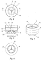
- Figs 1-4 show the connecting means 2 of the present invention, which is preferably formed from a single piece of plastics material.
- the connecting means 2 comprises a cylindrically shaped sleeve 6 having at its bottom edge an inwardly projecting and essentially horizontal shelf 8.
- the inner edge of shelf 8 projects downwardly to form a sleeve 22 having a smaller internal diameter than major sleeve 6.
- the internal diameter of sleeve 6 is chosen to form a close fit with the second container of the invention.
- two circumferentially extending ridges 10, 12 are located on the internal surface of sleeve 6 to promote a good grip between connecting means 2 and the second container (not shown).
- the internal diameter of smaller sleeve 22 is chosen to form a close fit with the top of first container of the present invention, which may conveniently be a conventionally sized neck collar of a commercially available aerosol canister.
- Figs 1-4 show a conduit extending through sleeve 6 at approximately the centre thereof.
- the conduit 14 is supported at its lower end by projections 16, 18 and 20 which extend from the inner edge of shelf 8 to the conduit. In the embodiment illustrated only three projections are shown, but more projections may also be present. Preferably the projections are spaced equidistantly from each other.
- the aperture of conduit 14 narrows at shoulder 15, the upper narrow portion of conduit 14 terminating in a blind ending 13.
- Small apertures 15a, 15b, 15c are present in conduit 14 and spaced equidistantly around shoulder 15. These apertures 15a, 15b and 15c are best seen in Figs 5-7.
- FIGs 5-7 and 8-9 demonstrate how connecting means 2 may be used to connect the first and second containers.
- the connecting means 2 can be pressed on to the first container 24, the inner surface of sleeve 22 forming a close fit with the external diameter of neck collar 26 on container 24.
- the internal diameter of the lower portion of conduit 14 is chosen to form a close fit with the standard valve 27 of container 24.
- Fig 5 shows a second container 28, having been aligned with connecting means 2, moving in the direction of the arrows in order to connect therewith.
- the second container 28 is then located within the upper portion of sleeve 6 and the packaging system may be stored and/or transported in this position.
- the bottom of container 28 is pushed as far as ridge 10 and the blind end 13 of conduit 14 is located directly beneath and abuts the Nicholson valve 30 sealing the bottom of the second container 28.
- the second container In order to activate the packaging system of the present invention and to initiate transfer of the first ingredient from the first container 24 into the second container 28, the second container is moved relative to the connecting means 2 into the position illustrated in Fig 7. As shown in Fig 7, conduit 14 has partially penetrated into the interior of container 28, the seal or Nicholson valve 30 being pushed inwardly and, as illustrated, retained upon the blind end 13 of conduit 14.
- the valve 27 of first container 24 is activated by pushing that container, and thus valve 27, into conduit 14 as far as shoulder 15.
- the presence of shoulder 15 in conduit 14 causes the valve 27 to be activated and the pressure within the first container 24 is released, the propellant therein expanding and causing displacement of the first ingredient along the conduit 14, through apertures 15a, 15b and 15c and into the interior of the second container 28.
- the apertures 15a, 15b, 15c are shaped, dimensioned and spaced to cause the first ingredient to be introduced into the interior of second container 28 in a spiral motion (eg having vortex characteristics) which causes admixture of the first and second ingredients.
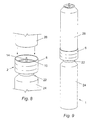
- Fig 8 illustrates a connecting means 2 positioned onto a first container 24 and ready to receive the second container 28 which is moving in the direction of the arrows.
- Fig 9 illustrates the first and second containers 24, 25 held in vertical juxtaposition by connecting means 2. Moving the second container 28 in a downward motion would cause activation of the upper valve 27, (shown in Figs 10 and 11) on the first container 24 and displacement of the first ingredient into the second container 28. Activation of the valve 34 (not shown) on top of the second container 28 would then allow dispension of the admixture of the first and second ingredients.
- the packaging system 1 of the present invention is designed specifically to aid dispension of ingredients which are normally incompatible during storage, complete deployment of the device would normally occur shortly after transfer of the first ingredient into the second container.
- Figs 10 and 11 show in schematic cross-section, the transfer of the first ingredient 25 from the first container 24 into the second container 28, to form an admixture 29 with the second ingredient.
- the first container 24 initially contains the first ingredient 25 (for example a foamable gel) separated from a pressurized propellant 32 (such as nitrogen gas/liquid system) by a piston 4.
- a pressurized propellant 32 such as nitrogen gas/liquid system
- the pressure of container 24 is released and propellant 32 expands driving a piston 4 upwardly and pushing first ingredient 25 through valve 27, conduit 14 and into the interior of the second container 28 via apertures 15a, 15b and 15c.
- the second container 28 initially holds the second ingredient 29 (which may be for example a powdered active ingredient) and a gas/liquid pressure system of a propellant 33.
- the propellant 33 comprises a significant volume of propellant in gaseous form, but upon the introduction of the first ingredient 25, at least part of the gaseous propellant is converted into liquid.
- the first and second ingredients have formed an intimate admixture 31. Admixture 31 is dispelled from the packaging system 1 by activation of valve 34 located on the upper end of container 28.
- a second preferred embodiment of the invention wherein the connecting means is a two-part connector 101.
- the connector 101 has a first part 100 which is designed to be immovably attached to a first container provided with a standard valve 300 and a second part 200 which is designed to be immovably attached to a second container 202.
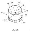
- Figs. 13 to 18 show the details of the first part 100 of the connector 101. More particularly Figs. 13 to 18 illustrate that the first part 100 comprises a cylindrically shaped sleeve 106 having at its bottom edge an inwardly projecting and essentially horizontal shelf 108. The internal diameter of sleeve 106 is chosen to co-operate with the second part 200 of connector 101 of the invention.
- the shelf 108 is pierced by apertures 126, 128 which are each provided below protuberances 110 and 112 located on the inner wall of the sleeve 106.
- abutments 124 are provided on the upper surface of the shelf 108, projecting upwardly from the latter and inwardly from the inner wall of the sleeve 106. These abutments 124 limit the extent of insertion of the second part 200 of the connector 101 when the second part 200 is introduced into the sleeve 106.
- abutments 124 are spaced equidistantly from each other.
- Figs. 13-17 two protuberances 110, 112 are located on the internal surface of sleeve 106 and these form a part of a locking system between the two parts 100 and 200 of the connector 101 which will be further described below.
- Fig. 17C shows in detail a preferred shape of protuberance 112. A corresponding shape would be used for the other protuberance 110.
- a fluted band 103 which can be made of equidistantly spaced ribs, is provided around the outer surface of the sleeve 106 and advantageously provides a good gripping surface for the user.
- the inner edge of shelf 108 projects downwardly to form a sleeve 122 having a smaller internal diameter that sleeve 106.
- the internal diameter of sleeve 122 is chosen to form a close fit with the top of the first container 102 which may conveniently be a conventionally sized neck collar of a commercially available aerosol canister.
- a snap bead 120 is advantageously provided at the bottom edge of the sleeve 122 to provide improved fitting with the neck collar of the first container 102.
- sleeve 122 At the upper portion of sleeve 122 a number of small ribs 119, best shown in Figs. 15, 16 and 18, are positioned projecting downwardly into the aperture of sleeve 122 and which are preferably equidistantly spaced from each other. These small ribs 119 act both as reinforcing members and spacing abutments with respect to the top of the first container 102.
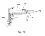
- Figs. 13 to 18 illustrate a conduit 114 extending partially along the aperture sleeve 106 and located at approximately the centre thereof.
- the conduit 114 is supported at its lower end by six (preferably identical) projections 116 which extend from the inner edge of shelf 108 to the conduit 114.
- projections 116 are spaced equidistantly from each other.
- the internal diameter of the conduit 114 is chosen to form a close fit with the dispensing tube of the first container 102 which is conveniently sized and shaped as a commercially available aerosol canister dispensing tube.
- the lower end of conduit 114 may terminate in an adaptor which is able to form the required close fit.
- Longitudinal reinforcing ribs 118 (shown in Fig. 18) are present on the inner wall of conduit 114 and may extend substantially along the length of the interior of conduit 114. Preferably there are three equidistantly spaced ribs 118.
- the thickness of the wall of conduit 114 may narrow at shoulder 115 reducing the external diameter whilst maintaining the aperture diameter.
- the upper portion of conduit 114 then terminates in a blind ending 113 which is of smaller cross-sectional area than conduit 114.
- Small apertures 117 are located in and spaced equidistantly around conduit 114.
- the apertures are located between shoulder 115 and blind end 113, and in this portion of conduit 114 narrows further, sloping inwardly to the blind end 113.
- the embodiment illustrated has three apertures 117 but this can of course be varied if required.
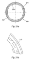
- Figs. 19 to 24 show the details of the second part 200 of the connector 101.
- the second part 200 of the connector 101 is sized and shaped to be located onto the bottom of a second container 202 in a tight fit arrangement.
- the second container 202 is sealed on its bottom surface by a bung 290 (for example a rubber bung or Nicholson valve) (see Figs. 25-27).
- the second part 200 comprises a cylindrically shaped sleeve 206 having at its inner bottom edge several ribs 208 which project inwardly into the aperture of sleeve 206 and are of arcuate form.
- the internal diameter of sleeve 206 is chosen to form a close fit with the bottom of the second container 202.
- the second part of the connector 101 is sized and shaped to receive the bottom of the second container in a close fit manner.
- the ribs 208 act as an additional attachment means and cooperate with the bottom end of the second container 202 in a snap bead manner.
- the external diameter of sleeve 206 is chosen to be generally smaller than the internal diameter of sleeve 106 of the first part 100 of the connector 101.
- the external diameter of the bottom part of the sleeve 206 is chosen so as to be generally larger than the internal diameter (taking into account the width of the protuberances 110, 112 of the locking system) of sleeve 106.
- the bottom end of the external surface of the sleeve 206 is provided with several successive curved and protruding ribs 216 which increase the external diameter of the sleeve 206.
- Two other sets of ribs 209, 211 and 213, 215 which define two pathways or tracks 210 (shown in Figs. 21-22) and 212 along the external surface of the bottom part of the sleeve 206 interrupt the ribs 216.
- Such pathways 210, 212 are sized and positioned to engage the two corresponding protuberances 110 and 112 provided inside the sleeve 106.
- the protuberances 110, 112 are located at the entrance of their respective pathway 210, 212.
- the protuberances 110, 112 are moved further along the pathways 210, 212 until the sleeve 206 becomes further positioned within the sleeve 106 to a pre-set maximum distance and the two parts 100, 200 of the connector 101 become locked together at a given position which is determined by the pathways 210 and 212.
- the blind end 113 has been pushed against the bung or Nicholson 290 valve sealing the bottom surface of the second container, displacing the bung or Nicholson valve 290 inwardly into the interior of that container 202.
- apertures 117 are located within the cavity of container 202 such that material dispensed from container 102 would be dispensed therethrough.
- the ribs 209, 211, 213, 215 and 216 which are provided on the external surface of the bottom end of the sleeve 206 are of a given width which allows close fitting of the sleeves 106, 206 of the two parts 100, 200 of the connector 101.
- fluted band 203 may be provided externally on the upper portion of the sleeve 206 to provide a good grip for the user's hand.
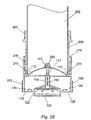
- Figs. 25 to 27 show the first part 100 and the second part 200 attached to the second container 202 in different connecting positions.
- the first part 100 can be pressed on to the first container 102, the inner surface of sleeve 122 forming a close fit with the external diameter of the neck collar provided on the first container 102 (not shown in Figs. 25 to 27).
- the internal diameter of the lower portion of conduit 114 is chosen to form a close fit with the standard valve 300 of container 102 (shown in Fig. 12 and which may be similar to the valve 27 of the previous embodiment (see Fig. 5).
- Figs. 25 to 27 show three positions that can be adopted by the connecting means 101, namely storage position, ready to be connected position and dispersing position. In Figs. 25 to 27 only a portion of container 202 is shown, and the first container 102 is not represented.
- Fig. 25 shows the connecting means 101 and a second container 202, attached to the second part 200 of the connector 101.
- Part 200 is positioned inside sleeve 106 of the first part 100, but the locking protuberances 110, 112 are not aligned with the entrance of the pathways 210 and 212 (not shown in that Figure).
- the blind end 113 of conduit 114 is located directly beneath and abuts the bung or Nicholson valve 290 sealing the bottom of the second container 202.
- a tamper band 302 can be provided between the two parts 100, 200 of the connector 101 in order to maintain them in that position and so that the packaging system may be then stored and/or transported without disturbance. This is the storage/distribution mode of the packaging system according to this embodiment of the invention.
- the conduit 114 is thus forced against bung or Nicholson valve 290, displacing it inwardly into the interior of container 202 and the packaging system of the present invention is ready for use.
- the transfer of the first ingredient from the first container 102 into the second container 202 may then be initiated, when required, simply by pressing the first container 102 against the connector 101, thus actuating the valve 300 of container 102 and causing transfer of the first ingredient into the second container via conduit 114 and apertures 117.
- the apertures 117 are shaped, sized and spaced to cause the first ingredient to be introduced into the interior of the second container 202 in a spiral motion (eg having vortex characteristics) which causes admixture of the first and second ingredients.
- the second container 202 is advantageously provided at its upper end with any suitable kind of dispensing system which permit the user to obtain the desired mixture of the two elements.
Landscapes
- Engineering & Computer Science (AREA)
- Mechanical Engineering (AREA)
- Chemical & Material Sciences (AREA)
- Dispersion Chemistry (AREA)
- Containers And Packaging Bodies Having A Special Means To Remove Contents (AREA)
- Agricultural Chemicals And Associated Chemicals (AREA)
- Packages (AREA)
- Basic Packing Technique (AREA)
- Nozzles (AREA)
- Container Filling Or Packaging Operations (AREA)
- Auxiliary Devices For And Details Of Packaging Control (AREA)
- Package Specialized In Special Use (AREA)
Claims (23)
- Un système d'emballage comportant :a) un premier contenant (24) ayant une soupape (27) contrôlant l'ouverture d'un orifice de sortie et contenant un premier ingrédient ; etb) un deuxième contenant (28) ayant une portion d'entrée pouvant être ouverte, contenant un deuxième ingrédient ; etc) un moyen de raccordement (2) comportant un conduit (14) destiné à raccorder ensemble lesdits premier et deuxième contenants (24, 28) dans le but de permettre le passage dudit premier ingrédient dudit premier contenant (24) dans le deuxième contenant (28) par le biais de la portion d'entrée de celui-ci et caractérisé en ce que ledit conduit (14) se termine par une extrémité aveugle (13) et possède des ouvertures multiples (15a, 15b, 15c) dans le côté dudit conduit (14) généralement adjacentes à l'extrémité aveugle (13) de celui-ci, lesdites ouvertures (15a, 15b, 15c) étant configurées et dimensionnées afin de distribuer le premier ingrédient en un écoulement en spirale de façon à favoriser l'admixtion des premier et deuxième ingrédients dans le deuxième contenant (28) pour former un produit final.
- Un système d'emballage tel que revendiqué dans la revendication 1, dans lequel lesdits premier et deuxième contenants (24, 28) sont chacun des contenants aérosol pressurisés et dans lequel la pression initiale dans le deuxième contenant (28) est inférieure à celle dans le premier contenant (24).
- Un système d'emballage tel que revendiqué dans l'une ou l'autre des revendications 1 et 2, dans lequel ladite portion d'entrée pouvant être ouverte est située dans le fond dudit deuxième contenant (28).
- Un système d'emballage tel que revendiqué dans n'importe laquelle des revendications 1 à 3, dans lequel ladite portion d'entrée pouvant être ouverte est une soupape Nicholson (30) ou une bonde.
- Un système d'emballage tel que revendiqué dans n'importe laquelle des revendications 1 à 4, dans lequel ledit premier contenant (24) est positionné en dessous du deuxième contenant (28) et raccordé à celui-ci par le biais du moyen de raccordement (2).
- Un système d'emballage tel que revendiqué dans n'importe laquelle des revendications 1 à 5, dans lequel ledit conduit (14) est configuré pour coopérer avec la soupape (27) du premier contenant (24).
- Un système d'emballage tel que revendiqué dans n'importe laquelle des revendications 1 à 6, dans lequel ladite soupape (27) dudit premier contenant (24) est une soupape activée par pression à décalage directionnel.
- Un système d'emballage tel que revendiqué dans n'importe laquelle des revendications 1 à 7, dans lequel ledit moyen de raccordement (2) comporte un premier manchon (22) faisant saillie vers le bas, lequel se met en prise avec le dessus du premier contenant (24) et un deuxième manchon (6) faisant saillie vers le haut, lequel se met en prise avec le fond du deuxième contenant (28).
- Un système d'emballage tel que revendiqué dans la revendication 8, dans lequel lesdits premier et deuxième manchons (22, 6) sont calibrés et configurés pour former un ajustement sans jeu avec chacun desdits contenants (24, 28).
- Un système d'emballage tel que revendiqué dans n'importe laquelle des revendications 1 à 9, dans lequel ledit moyen de raccordement (2) est un organe d'une seule pièce.
- Un système d'emballage tel que revendiqué dans la revendication 8, dans lequel ledit moyen de raccordement (2) comporte au moins une première partie (100) et une deuxième partie (200), lesquelles peuvent tourner l'une par rapport à l'autre, ladite première partie (100) comportant ledit conduit (14) et lesdits premier et deuxième manchons (22, 6), et ladite deuxième partie (200) comportant un troisième manchon (206) assujetti au fond du deuxième contenant (28), lesdits deuxième et troisième manchons (6, 206) ayant des filetages de vis correspondants, ce qui permet auxdits deuxième et troisième manchons (22, 6) d'être déplacés d'une première position où le conduit (14) n'actionne pas ladite portion d'entrée pouvant être ouverte à une deuxième position où ledit conduit (14) actionne ladite portion d'entrée pouvant être ouverte.
- Un système d'emballage tel que revendiqué dans la revendication 11, dans lequel ledit moyen de raccordement (2) comporte un mécanisme d'encliquetage pour empêcher l'inversion de la rotation des première et deuxième parties.
- Un système d'emballage tel que revendiqué dans l'une ou l'autre des revendications 11 et 12, dans lequel ladite rotation des première et deuxième parties (100, 200) l'une par rapport à l'autre se fait sur approximativement 120°.
- Un système d'emballage tel que revendiqué dans n'importe laquelle des revendications 1 à 13, dans lequel ledit deuxième contenant (28) a un actionneur monté sur le dessus, lequel contrôle la distribution de son contenu.
- Un système d'emballage tel que revendiqué dans n'importe laquelle des revendications 1 à 14, dans lequel ledit deuxième ingrédient est une poudre et dans lequel ledit premier ingrédient est un gel.
- Un système d'emballage tel que revendiqué dans n'importe laquelle des revendications 1 à 15, dans lequel l'orifice de sortie dudit premier contenant (24) est une soupape unidirectionnelle.
- Un système d'emballage tel que revendiqué dans n'importe laquelle des revendications 1 à 16, dans lequel ledit deuxième contenant (28) contient un propulseur, lequel est aussi un excipient du produit final.
- Un système d'emballage tel que revendiqué dans n'importe laquelle des revendications 1 à 17, dans lequel ledit moyen de raccordement (2) est réalisé en matière plastique.
- Un système d'emballage tel que revendiqué dans n'importe laquelle des revendications 1 à 18, dans lequel ledit premier contenant (24) est sélectionné dans le groupe composé d'un contenant aérosol de style à piston où ledit premier ingrédient est séparé du gaz propulseur au moyen d'un piston et d'un contenant aérosol dont la boíte renferme un sac où le premier ingrédient est séparé du propulseur au moyen d'un sac.
- Un système d'emballage tel que revendiqué dans n'importe laquelle des revendications 1 à 19, dans lequel ledit deuxième contenant (28) contient un gaz propulseur, lequel ne réagit pas avec les premier et deuxième ingrédients.
- Un système d'emballage tel que revendiqué dans n'importe lesquelles des revendications 1 à 20, dans lequel le conduit (14) coopère avec ladite entrée pouvant être ouverte du deuxième contenant (28) de telle sorte que, lorsque l'entrée pouvant être ouverte est ouverte, le conduit (14) permette à l'entrée du premier ingrédient dans le deuxième contenant (28) d'avoir lieu.
- Un système d'emballage tel que revendiqué dans n'importe laquelle des revendications 1 à 21, dans lequel le deuxième contenant (28) a une soupape Nicholson (30) montée au fond, qui est ôtée ou que ledit conduit (14) fait passer dans le deuxième contenant pour permettre l'entrée du premier ingrédient dans le deuxième contenant (28).
- Un système d'emballage tel que revendiqué dans n'importe laquelle des revendications 1 à 22, dans lequel le moyen pour actionner le passage dudit premier ingrédient audit deuxième contenant (28) comporte un moyen pour tenir les premier et deuxième contenants (24, 28) dans une juxtaposition appropriée.
Applications Claiming Priority (3)
| Application Number | Priority Date | Filing Date | Title |
|---|---|---|---|
| GB9823029 | 1998-10-22 | ||
| GBGB9823029.5A GB9823029D0 (en) | 1998-10-22 | 1998-10-22 | Packaging system |
| PCT/GB1999/003516 WO2000024649A1 (fr) | 1997-05-07 | 1999-10-22 | Systeme de conditionnement servant a melanger et a distribuer des produits contenant des ingredients multiples |
Publications (2)
| Publication Number | Publication Date |
|---|---|
| EP1127016A1 EP1127016A1 (fr) | 2001-08-29 |
| EP1127016B1 true EP1127016B1 (fr) | 2003-09-17 |
Family
ID=10841008
Family Applications (1)
| Application Number | Title | Priority Date | Filing Date |
|---|---|---|---|
| EP99950970A Expired - Lifetime EP1127016B1 (fr) | 1998-10-22 | 1999-10-22 | Systeme de conditionnement servant a melanger et a distribuer des produits contenant des ingredients multiples |
Country Status (12)
| Country | Link |
|---|---|
| US (1) | US6435231B1 (fr) |
| EP (1) | EP1127016B1 (fr) |
| JP (1) | JP4243024B2 (fr) |
| AT (1) | ATE249985T1 (fr) |
| AU (1) | AU6355699A (fr) |
| CA (1) | CA2338366C (fr) |
| DE (1) | DE69911451T2 (fr) |
| DK (1) | DK1127016T3 (fr) |
| ES (1) | ES2207294T3 (fr) |
| GB (1) | GB9823029D0 (fr) |
| PT (1) | PT1127016E (fr) |
| WO (1) | WO2000024649A1 (fr) |
Families Citing this family (49)
| Publication number | Priority date | Publication date | Assignee | Title |
|---|---|---|---|---|
| ES2068151B1 (es) | 1993-06-23 | 1995-11-16 | Cabrera Garrido Juan | Microespuma inyectable para esclerosis. |
| GB9912356D0 (en) | 1999-05-26 | 1999-07-28 | Btg Int Ltd | Generation of microfoam |
| GB0028692D0 (en) | 2000-11-24 | 2001-01-10 | Btg Int Ltd | Generation of therapeutic microform |
| AUPR402101A0 (en) * | 2001-03-27 | 2001-04-26 | Hall, Allen Beaumont | Dispenser |
| US8512680B2 (en) | 2001-08-08 | 2013-08-20 | Btg International Ltd. | Injectables in foam, new pharmaceutical applications |
| KR200256383Y1 (ko) | 2001-09-19 | 2001-12-14 | 송감섭 | 서로 다른 성분의 분말 또는 용액을 분리보관 및 혼합사용할 수 있는 용기 |
| US6848601B2 (en) * | 2002-03-14 | 2005-02-01 | Homax Products, Inc. | Aerosol systems and methods for mixing and dispensing two-part materials |
| US7063236B2 (en) * | 2002-03-14 | 2006-06-20 | Homax Products, Inc. | Aerosol systems and methods for mixing and dispensing two-part materials |
| FR2850564B1 (fr) | 2003-02-05 | 2006-06-02 | Arcadophta | Dispositif et procede de preparation extemporanee d'une quantite individuelle de fluide sterile |
| US7543284B2 (en) | 2003-04-22 | 2009-06-02 | Transitive Limited | Partial dead code elimination optimizations for program code conversion |
| US6883564B2 (en) * | 2003-07-22 | 2005-04-26 | Thomas M. Risch | Pressurizing system for a dispensing container |
| US7763269B2 (en) | 2003-11-17 | 2010-07-27 | Btg International Ltd. | Therapeutic foam |
| US8048439B2 (en) | 2003-11-17 | 2011-11-01 | Btg International Ltd. | Therapeutic foam |
| IL161515A (en) * | 2004-04-20 | 2012-10-31 | Beauty Union Global Ltd | Refill perfume bottle |
| EP1836104B1 (fr) * | 2004-12-28 | 2009-01-21 | Nanosys GMBH | Recipient sous pression destine a distribuer une substance a plusieurs composants contenue dans ledit recipient |
| GB0509824D0 (en) | 2005-05-13 | 2005-06-22 | Btg Int Ltd | Therapeutic foam |
| US20070244467A1 (en) * | 2005-09-28 | 2007-10-18 | Biodel, Inc., State Of Incorporation Delaware | Self-Filling Two Chamber Injectable Device |
| EP1979240A1 (fr) * | 2006-01-26 | 2008-10-15 | Frederick Gibb | Indicateur de faible niveau de remplissage pour distributeur |
| US20070275125A1 (en) * | 2006-05-26 | 2007-11-29 | Catani Steven J | Method of delivering an active component to a liquid foodstuff in a container with a narrow opening |
| JP4862514B2 (ja) * | 2006-06-22 | 2012-01-25 | 凸版印刷株式会社 | 円筒型タブレット容器 |
| EP2159162A1 (fr) * | 2008-08-29 | 2010-03-03 | KPSS-Kao Professional Salon Services GmbH | Conteneur |
| CN201329329Y (zh) | 2008-12-26 | 2009-10-21 | 东莞怡信磁碟有限公司 | 改进型便携可充式喷液瓶 |
| JP2012517943A (ja) * | 2009-02-13 | 2012-08-09 | ガリナ,ポロ | 液体化粧品を移す分配装置 |
| GB0902626D0 (en) * | 2009-02-17 | 2009-04-01 | Farrar Peter A | Combination pack for personal care products |
| JP5229822B2 (ja) * | 2009-06-30 | 2013-07-03 | 株式会社吉野工業所 | 定量ポンプ |
| JP5900776B2 (ja) * | 2010-03-31 | 2016-04-06 | ビューティー ユニオン グローバル リミテッドBeauty Union Global Limited | 補給システムおよび方法 |
| GB2483087A (en) * | 2010-08-26 | 2012-02-29 | Breeze Product Design Ltd | Refillable Dispenser with Deformable Membrane |
| BR112013018381A2 (pt) | 2011-02-11 | 2017-09-05 | Procter & Gamble | Métodos, dispositivos e sistemas para reabstecimento de um dispensador de fluidos |
| CN102259714B (zh) | 2011-07-26 | 2012-08-22 | 东莞怡信磁碟有限公司 | 一种便携式乳膏充液瓶 |
| US20140183222A1 (en) * | 2012-10-19 | 2014-07-03 | Rust-Oleum Corporation | Propellantless Aerosol System |
| CN202999725U (zh) | 2012-11-08 | 2013-06-19 | 东莞怡信磁碟有限公司 | 一种香水瓶的瓶体结构 |
| US10279362B2 (en) | 2012-11-16 | 2019-05-07 | Zhejiang JM Industry Co., Ltd | Auto refill perfume atomizer apparatus |
| US9365408B2 (en) * | 2012-11-16 | 2016-06-14 | Zhejiang Jm Industry Co., Ltd. | Auto refill perfume atomizer |
| WO2014085258A1 (fr) * | 2012-11-29 | 2014-06-05 | Board Of Regents, The University Of Texas System | Mélangeur de perfusion robotique et cartouche transportable |
| KR101478978B1 (ko) * | 2013-01-15 | 2015-01-07 | (주)연우 | 이종 내용물 혼합용기 |
| US8978935B2 (en) * | 2013-01-30 | 2015-03-17 | Seymour Of Sycamore, Inc. | Liquid spray system |
| FR3004429B1 (fr) * | 2013-04-16 | 2015-11-27 | Rexam Dispensing Sys | Ensemble comprenant un flacon remplissable et une source de produit |
| US9919323B2 (en) * | 2015-02-02 | 2018-03-20 | Gojo Industries, Inc. | Fluid dispenser and first and second fluid containers for a fluid dispenser |
| US10179690B2 (en) | 2016-05-26 | 2019-01-15 | Rai Strategic Holdings, Inc. | Aerosol precursor composition mixing system for an aerosol delivery device |
| WO2018081942A1 (fr) * | 2016-11-02 | 2018-05-11 | The Procter & Gamble Company | Diffuseur de composition volatile ayant une pompe à air et méthode de distribution de composition volatile à une surface d'évaporation l'utilisant |
| MY206250A (en) | 2018-02-05 | 2024-12-05 | Ecolab Usa Inc | Packaging and docking system for non-contact chemical dispensing |
| ES2926141T3 (es) | 2018-02-13 | 2022-10-24 | Ecolab Usa Inc | Sistema y método para disolver productos químicos sólidos y generar soluciones líquidas |
| AU2020219781B2 (en) | 2019-02-05 | 2025-12-18 | Ecolab Usa Inc. | Packaging and docking system for non-contact chemical dispensing |
| CA3141803A1 (fr) | 2019-05-30 | 2020-12-03 | Ecolab Usa Inc. | Systeme de distribution pour le transfert d'un produit chimique dans un ensemble panier de crepine |
| GB2586441B (en) | 2019-06-24 | 2022-01-12 | Prodromou Phrixos | Dispenser |
| US11186423B2 (en) * | 2020-03-20 | 2021-11-30 | Seymour Of Sycamore Inc. | Liquid spray system |
| RU2766471C1 (ru) * | 2021-05-24 | 2022-03-15 | Общество с ограниченной ответственностью Предприятие "Полихим-Воронеж" | Способ заправки аэрозольных баллонов двухкомпонентными материалами |
| JP7727314B2 (ja) * | 2021-07-16 | 2025-08-21 | 株式会社ダイゾー | 移充填システム、移充填方法 |
| WO2023127035A1 (fr) * | 2021-12-27 | 2023-07-06 | 東洋エアゾール工業株式会社 | Système d'aérosol de recharge |
Family Cites Families (10)
| Publication number | Priority date | Publication date | Assignee | Title |
|---|---|---|---|---|
| NL298537A (fr) * | 1962-09-27 | |||
| US3181737A (en) | 1963-09-30 | 1965-05-04 | R H Macy & Co Inc | Method of storing, combining and applying two-part polymer mixtures |
| FR2105332A5 (fr) | 1970-09-01 | 1972-04-28 | Oreal | |
| US4197884A (en) * | 1975-12-08 | 1980-04-15 | Dispenser Corporation | Airless sprayer and pressurizing system |
| DE3116282A1 (de) | 1981-04-24 | 1982-11-11 | Henkel KGaA, 4000 Düsseldorf | "aerosol-verpackung" |
| GB2142385B (en) * | 1983-06-28 | 1986-12-17 | Brooks William R | Mechanical delivery system for a catalyst or the like |
| IT1173370B (it) * | 1984-02-24 | 1987-06-24 | Erba Farmitalia | Dispositivo di sicurezza per collegare una siringa alla imboccatura di un flacone contenente un farmaco o di un tubicino per l'erogazione del farmaco della siringa |
| GB8522813D0 (en) | 1985-09-16 | 1985-10-23 | Unilever Plc | Package |
| US4750314A (en) * | 1986-01-13 | 1988-06-14 | American National Can Company | Method for propellant filling and sealing of a container |
| DE8704600U1 (de) | 1987-03-27 | 1987-10-15 | Cocon Kunststoffen B.V., Arkel | Vorrichtung zur gebrauchsfertigen Zubereitung der beiden Komponenten eines zweikomponentigen Montageschaums, insbesondere Polyurethanschaums |
-
1998
- 1998-10-22 GB GBGB9823029.5A patent/GB9823029D0/en not_active Ceased
-
1999
- 1999-10-22 EP EP99950970A patent/EP1127016B1/fr not_active Expired - Lifetime
- 1999-10-22 JP JP2000578225A patent/JP4243024B2/ja not_active Expired - Fee Related
- 1999-10-22 WO PCT/GB1999/003516 patent/WO2000024649A1/fr not_active Ceased
- 1999-10-22 AU AU63556/99A patent/AU6355699A/en not_active Abandoned
- 1999-10-22 CA CA002338366A patent/CA2338366C/fr not_active Expired - Fee Related
- 1999-10-22 DE DE69911451T patent/DE69911451T2/de not_active Expired - Lifetime
- 1999-10-22 AT AT99950970T patent/ATE249985T1/de active
- 1999-10-22 PT PT99950970T patent/PT1127016E/pt unknown
- 1999-10-22 US US09/786,969 patent/US6435231B1/en not_active Expired - Lifetime
- 1999-10-22 ES ES99950970T patent/ES2207294T3/es not_active Expired - Lifetime
- 1999-10-22 DK DK99950970T patent/DK1127016T3/da active
Also Published As
| Publication number | Publication date |
|---|---|
| JP2002528349A (ja) | 2002-09-03 |
| ATE249985T1 (de) | 2003-10-15 |
| WO2000024649A1 (fr) | 2000-05-04 |
| CA2338366A1 (fr) | 2000-05-04 |
| AU6355699A (en) | 2000-05-15 |
| JP4243024B2 (ja) | 2009-03-25 |
| US6435231B1 (en) | 2002-08-20 |
| DE69911451D1 (de) | 2003-10-23 |
| PT1127016E (pt) | 2004-02-27 |
| CA2338366C (fr) | 2008-01-08 |
| DK1127016T3 (da) | 2004-01-26 |
| EP1127016A1 (fr) | 2001-08-29 |
| DE69911451T2 (de) | 2004-07-08 |
| ES2207294T3 (es) | 2004-05-16 |
| GB9823029D0 (en) | 1998-12-16 |
Similar Documents
| Publication | Publication Date | Title |
|---|---|---|
| EP1127016B1 (fr) | Systeme de conditionnement servant a melanger et a distribuer des produits contenant des ingredients multiples | |
| US6609634B2 (en) | Dispensing device and methods | |
| US5692644A (en) | Container for storing at least two products, mixing these products, and dispensing the mixture thus obtained | |
| US3608782A (en) | Device for holding two products separately and dispensing them simultaneously | |
| CN100564239C (zh) | 混合和分配第一和第二流体的气溶胶分配器以及用第一和第二流体填充气溶胶分配器的方法 | |
| US4518103A (en) | Method and apparatus for releasing additional ingredients in a pressurized container | |
| US6923342B2 (en) | Systems for dispensing multi-component products | |
| US3255926A (en) | Compartmented pressurized dispensing device | |
| US3540623A (en) | Multi-product dispenser with co-dispensing valving means | |
| EP1569854B1 (fr) | Systeme d'assemblage de contenant a plusieurs compartiments | |
| US20020003147A1 (en) | Container assembly for dispensing non-atomized composition mixed internally upon dispensing | |
| US9434530B2 (en) | Selectable, multiple chamber container having single nozzle assembly | |
| KR20030007576A (ko) | 다중 격실 컨테이너 | |
| CA2572799A1 (fr) | Ensemble seringue | |
| CN100581940C (zh) | 容器内冷冻加气产品及其制造方法 | |
| IL176198A (en) | Release device with measured dose valve | |
| CN110550335B (zh) | 用于气溶胶系统的容器 | |
| US7357158B2 (en) | Aerosol dispenser for mixing and dispensing multiple fluid products | |
| US3667652A (en) | Method and apparatus for separately packaging two liquids which are to be simultaneously dispensed | |
| JP2995511B2 (ja) | 加圧分与装置 | |
| US5425475A (en) | Epoxy dispenser | |
| US3272402A (en) | Aerosol dispensing apparatus | |
| US4298119A (en) | Multiple compartment containers | |
| US3420033A (en) | Method of filling and assembling compartmented dispensing device | |
| WO1998015463A1 (fr) | Contenant de stockage, de melange et de distribution de formulations |
Legal Events
| Date | Code | Title | Description |
|---|---|---|---|
| PUAI | Public reference made under article 153(3) epc to a published international application that has entered the european phase |
Free format text: ORIGINAL CODE: 0009012 |
|
| 17P | Request for examination filed |
Effective date: 20010117 |
|
| AK | Designated contracting states |
Kind code of ref document: A1 Designated state(s): AT BE CH CY DE DK ES FI FR GB GR IE IT LI LU MC NL PT SE |
|
| 17Q | First examination report despatched |
Effective date: 20010831 |
|
| GRAH | Despatch of communication of intention to grant a patent |
Free format text: ORIGINAL CODE: EPIDOS IGRA |
|
| GRAS | Grant fee paid |
Free format text: ORIGINAL CODE: EPIDOSNIGR3 |
|
| GRAA | (expected) grant |
Free format text: ORIGINAL CODE: 0009210 |
|
| AK | Designated contracting states |
Kind code of ref document: B1 Designated state(s): AT BE CH CY DE DK ES FI FR GB GR IE IT LI LU MC NL PT SE |
|
| REG | Reference to a national code |
Ref country code: GB Ref legal event code: FG4D |
|
| REG | Reference to a national code |
Ref country code: CH Ref legal event code: EP |
|
| REF | Corresponds to: |
Ref document number: 69911451 Country of ref document: DE Date of ref document: 20031023 Kind code of ref document: P |
|
| REG | Reference to a national code |
Ref country code: IE Ref legal event code: FG4D |
|
| REG | Reference to a national code |
Ref country code: CH Ref legal event code: NV Representative=s name: ROSENICH PAUL; GISLER CHRISTIAN PATENTBUERO PAUL R |
|
| REG | Reference to a national code |
Ref country code: SE Ref legal event code: TRGR |
|
| REG | Reference to a national code |
Ref country code: DK Ref legal event code: T3 |
|
| REG | Reference to a national code |
Ref country code: GR Ref legal event code: EP Ref document number: 20030405119 Country of ref document: GR |
|
| REG | Reference to a national code |
Ref country code: ES Ref legal event code: FG2A Ref document number: 2207294 Country of ref document: ES Kind code of ref document: T3 |
|
| ET | Fr: translation filed | ||
| PLBE | No opposition filed within time limit |
Free format text: ORIGINAL CODE: 0009261 |
|
| STAA | Information on the status of an ep patent application or granted ep patent |
Free format text: STATUS: NO OPPOSITION FILED WITHIN TIME LIMIT |
|
| 26N | No opposition filed |
Effective date: 20040618 |
|
| PGFP | Annual fee paid to national office [announced via postgrant information from national office to epo] |
Ref country code: MC Payment date: 20070927 Year of fee payment: 9 |
|
| PGFP | Annual fee paid to national office [announced via postgrant information from national office to epo] |
Ref country code: NL Payment date: 20070920 Year of fee payment: 9 |
|
| PGFP | Annual fee paid to national office [announced via postgrant information from national office to epo] |
Ref country code: CY Payment date: 20071015 Year of fee payment: 9 |
|
| PGFP | Annual fee paid to national office [announced via postgrant information from national office to epo] |
Ref country code: LU Payment date: 20080401 Year of fee payment: 9 |
|
| REG | Reference to a national code |
Ref country code: CH Ref legal event code: NV Representative=s name: BRAUNPAT BRAUN EDER AG |
|
| PG25 | Lapsed in a contracting state [announced via postgrant information from national office to epo] |
Ref country code: MC Free format text: LAPSE BECAUSE OF NON-PAYMENT OF DUE FEES Effective date: 20081031 |
|
| NLV4 | Nl: lapsed or anulled due to non-payment of the annual fee |
Effective date: 20090501 |
|
| PG25 | Lapsed in a contracting state [announced via postgrant information from national office to epo] |
Ref country code: NL Free format text: LAPSE BECAUSE OF NON-PAYMENT OF DUE FEES Effective date: 20090501 |
|
| PG25 | Lapsed in a contracting state [announced via postgrant information from national office to epo] |
Ref country code: CY Free format text: LAPSE BECAUSE OF NON-PAYMENT OF DUE FEES Effective date: 20081022 |
|
| PG25 | Lapsed in a contracting state [announced via postgrant information from national office to epo] |
Ref country code: LU Free format text: LAPSE BECAUSE OF NON-PAYMENT OF DUE FEES Effective date: 20081022 |
|
| PGFP | Annual fee paid to national office [announced via postgrant information from national office to epo] |
Ref country code: DK Payment date: 20141024 Year of fee payment: 16 |
|
| PGFP | Annual fee paid to national office [announced via postgrant information from national office to epo] |
Ref country code: DE Payment date: 20141021 Year of fee payment: 16 Ref country code: IE Payment date: 20141017 Year of fee payment: 16 Ref country code: ES Payment date: 20141023 Year of fee payment: 16 Ref country code: FI Payment date: 20141020 Year of fee payment: 16 Ref country code: FR Payment date: 20141022 Year of fee payment: 16 Ref country code: SE Payment date: 20141021 Year of fee payment: 16 Ref country code: CH Payment date: 20141121 Year of fee payment: 16 Ref country code: GR Payment date: 20141027 Year of fee payment: 16 Ref country code: GB Payment date: 20141008 Year of fee payment: 16 |
|
| PGFP | Annual fee paid to national office [announced via postgrant information from national office to epo] |
Ref country code: PT Payment date: 20141010 Year of fee payment: 16 Ref country code: AT Payment date: 20141023 Year of fee payment: 16 |
|
| PGFP | Annual fee paid to national office [announced via postgrant information from national office to epo] |
Ref country code: IT Payment date: 20141027 Year of fee payment: 16 |
|
| PGFP | Annual fee paid to national office [announced via postgrant information from national office to epo] |
Ref country code: BE Payment date: 20141021 Year of fee payment: 16 |
|
| REG | Reference to a national code |
Ref country code: PT Ref legal event code: MM4A Free format text: LAPSE DUE TO NON-PAYMENT OF FEES Effective date: 20160422 |
|
| REG | Reference to a national code |
Ref country code: DE Ref legal event code: R119 Ref document number: 69911451 Country of ref document: DE |
|
| REG | Reference to a national code |
Ref country code: DK Ref legal event code: EBP Effective date: 20151031 |
|
| REG | Reference to a national code |
Ref country code: CH Ref legal event code: PL Ref country code: SE Ref legal event code: EUG |
|
| REG | Reference to a national code |
Ref country code: AT Ref legal event code: MM01 Ref document number: 249985 Country of ref document: AT Kind code of ref document: T Effective date: 20151022 |
|
| GBPC | Gb: european patent ceased through non-payment of renewal fee |
Effective date: 20151022 |
|
| REG | Reference to a national code |
Ref country code: GR Ref legal event code: ML Ref document number: 20030405119 Country of ref document: GR Effective date: 20160506 |
|
| REG | Reference to a national code |
Ref country code: IE Ref legal event code: MM4A |
|
| PG25 | Lapsed in a contracting state [announced via postgrant information from national office to epo] |
Ref country code: IT Free format text: LAPSE BECAUSE OF NON-PAYMENT OF DUE FEES Effective date: 20151022 Ref country code: LI Free format text: LAPSE BECAUSE OF NON-PAYMENT OF DUE FEES Effective date: 20151031 Ref country code: GR Free format text: LAPSE BECAUSE OF NON-PAYMENT OF DUE FEES Effective date: 20160506 Ref country code: DE Free format text: LAPSE BECAUSE OF NON-PAYMENT OF DUE FEES Effective date: 20160503 Ref country code: GB Free format text: LAPSE BECAUSE OF NON-PAYMENT OF DUE FEES Effective date: 20151022 Ref country code: CH Free format text: LAPSE BECAUSE OF NON-PAYMENT OF DUE FEES Effective date: 20151031 |
|
| REG | Reference to a national code |
Ref country code: FR Ref legal event code: ST Effective date: 20160630 |
|
| PG25 | Lapsed in a contracting state [announced via postgrant information from national office to epo] |
Ref country code: FR Free format text: LAPSE BECAUSE OF NON-PAYMENT OF DUE FEES Effective date: 20151102 Ref country code: PT Free format text: LAPSE BECAUSE OF NON-PAYMENT OF DUE FEES Effective date: 20160422 Ref country code: SE Free format text: LAPSE BECAUSE OF NON-PAYMENT OF DUE FEES Effective date: 20151023 Ref country code: AT Free format text: LAPSE BECAUSE OF NON-PAYMENT OF DUE FEES Effective date: 20151022 |
|
| PG25 | Lapsed in a contracting state [announced via postgrant information from national office to epo] |
Ref country code: IE Free format text: LAPSE BECAUSE OF NON-PAYMENT OF DUE FEES Effective date: 20151022 Ref country code: DK Free format text: LAPSE BECAUSE OF NON-PAYMENT OF DUE FEES Effective date: 20151031 |
|
| REG | Reference to a national code |
Ref country code: ES Ref legal event code: FD2A Effective date: 20161125 |
|
| PG25 | Lapsed in a contracting state [announced via postgrant information from national office to epo] |
Ref country code: ES Free format text: LAPSE BECAUSE OF NON-PAYMENT OF DUE FEES Effective date: 20151023 |
|
| PG25 | Lapsed in a contracting state [announced via postgrant information from national office to epo] |
Ref country code: FI Free format text: LAPSE BECAUSE OF NON-PAYMENT OF DUE FEES Effective date: 20151022 |
|
| PG25 | Lapsed in a contracting state [announced via postgrant information from national office to epo] |
Ref country code: BE Free format text: LAPSE BECAUSE OF NON-PAYMENT OF DUE FEES Effective date: 20151031 |