EP1127227B1 - Frein de servomoteur - Google Patents
Frein de servomoteur Download PDFInfo
- Publication number
- EP1127227B1 EP1127227B1 EP99958790A EP99958790A EP1127227B1 EP 1127227 B1 EP1127227 B1 EP 1127227B1 EP 99958790 A EP99958790 A EP 99958790A EP 99958790 A EP99958790 A EP 99958790A EP 1127227 B1 EP1127227 B1 EP 1127227B1
- Authority
- EP
- European Patent Office
- Prior art keywords
- axial
- input
- control apparatus
- rotational control
- extending
- Prior art date
- Legal status (The legal status is an assumption and is not a legal conclusion. Google has not performed a legal analysis and makes no representation as to the accuracy of the status listed.)
- Expired - Lifetime
Links
- 239000012530 fluid Substances 0.000 claims abstract description 9
- 230000008878 coupling Effects 0.000 claims abstract description 8
- 238000010168 coupling process Methods 0.000 claims abstract description 8
- 238000005859 coupling reaction Methods 0.000 claims abstract description 8
- 239000000463 material Substances 0.000 claims description 3
- 230000003247 decreasing effect Effects 0.000 claims description 2
- 230000001419 dependent effect Effects 0.000 claims description 2
- 238000004519 manufacturing process Methods 0.000 description 4
- 230000004323 axial length Effects 0.000 description 2
- 230000000717 retained effect Effects 0.000 description 2
- 230000006835 compression Effects 0.000 description 1
- 238000007906 compression Methods 0.000 description 1
- 238000010276 construction Methods 0.000 description 1
- 238000010348 incorporation Methods 0.000 description 1
- 238000007789 sealing Methods 0.000 description 1
- 230000003068 static effect Effects 0.000 description 1
- 230000002195 synergetic effect Effects 0.000 description 1
- 230000000007 visual effect Effects 0.000 description 1
Images

Classifications
-
- H—ELECTRICITY
- H02—GENERATION; CONVERSION OR DISTRIBUTION OF ELECTRIC POWER
- H02K—DYNAMO-ELECTRIC MACHINES
- H02K7/00—Arrangements for handling mechanical energy structurally associated with dynamo-electric machines, e.g. structural association with mechanical driving motors or auxiliary dynamo-electric machines
- H02K7/10—Structural association with clutches, brakes, gears, pulleys or mechanical starters
- H02K7/102—Structural association with clutches, brakes, gears, pulleys or mechanical starters with friction brakes
-
- F—MECHANICAL ENGINEERING; LIGHTING; HEATING; WEAPONS; BLASTING
- F16—ENGINEERING ELEMENTS AND UNITS; GENERAL MEASURES FOR PRODUCING AND MAINTAINING EFFECTIVE FUNCTIONING OF MACHINES OR INSTALLATIONS; THERMAL INSULATION IN GENERAL
- F16D—COUPLINGS FOR TRANSMITTING ROTATION; CLUTCHES; BRAKES
- F16D55/00—Brakes with substantially-radial braking surfaces pressed together in axial direction, e.g. disc brakes
- F16D55/02—Brakes with substantially-radial braking surfaces pressed together in axial direction, e.g. disc brakes with axially-movable discs or pads pressed against axially-located rotating members
-
- F—MECHANICAL ENGINEERING; LIGHTING; HEATING; WEAPONS; BLASTING
- F16—ENGINEERING ELEMENTS AND UNITS; GENERAL MEASURES FOR PRODUCING AND MAINTAINING EFFECTIVE FUNCTIONING OF MACHINES OR INSTALLATIONS; THERMAL INSULATION IN GENERAL
- F16D—COUPLINGS FOR TRANSMITTING ROTATION; CLUTCHES; BRAKES
- F16D59/00—Self-acting brakes, e.g. coming into operation at a predetermined speed
- F16D59/02—Self-acting brakes, e.g. coming into operation at a predetermined speed spring-loaded and adapted to be released by mechanical, fluid, or electromagnetic means
-
- F—MECHANICAL ENGINEERING; LIGHTING; HEATING; WEAPONS; BLASTING
- F16—ENGINEERING ELEMENTS AND UNITS; GENERAL MEASURES FOR PRODUCING AND MAINTAINING EFFECTIVE FUNCTIONING OF MACHINES OR INSTALLATIONS; THERMAL INSULATION IN GENERAL
- F16D—COUPLINGS FOR TRANSMITTING ROTATION; CLUTCHES; BRAKES
- F16D65/00—Parts or details
- F16D65/02—Braking members; Mounting thereof
- F16D2065/024—Braking members; Mounting thereof the braking surface being inclined with respect to the rotor's axis of rotation at an angle other than 90 degrees, e.g. comprising a conical rotor
Definitions
- the present invention generally relates to apparatus for controlling rotation of an input relative to an output, such as for example in servo-motor brakes.
- Servo-motors are increasingly being used as drives in the control of machinery component movement.
- servo-motor applications where it is desirable to stop movement of the machinery component being driven including but not limited to parking or emergency stop situations but also in the event of disruption of power to the servo-motor.
- servo-motors were purchased from manufacturers either with or without an integral braking component.
- a need has arisen for a brake to be added as a module separately to servo-motors.
- it would be desirable that such add on servo-motor brakes have performance characteristics which exceed those of integral servo-motor and brake units and which minimize the overall product size.
- the drive shafts of servo-motors are of different radial sizes.
- the sizes and shapes of pilot faces differ between manufacturers of servo-motors.
- the output face includes four bores which may be threaded and which were located at the corners of a square larger than the pilot and for receipt of screws extending from the apparatus component to be driven, such bores were of different diameters and were located at different radial spacings from the drive shaft.
- brakes intended to be modules for attachment to servo-motors should have universal application to all servo-motors of whatever manufacturer and should be easily and readily modifiable to that of the particular servo-motor to which it is desired to be attached.
- the present invention aims to solve this need and other problems in the field of rotation control.
- DE-A-636 888 discloses rotational control apparatus according to the preamble of claim 1.
- the present invention is distinguished by the features claimed in the characterising part of claim 1.
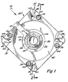
- a rotational control apparatus is shown in the drawings as a spring engaged fluid released brake and is generally designated 10.
- Brake 10 is shown in its most preferred form for rotationally controlling an input 12.
- Input 12 generally includes a first axial portion 14 and a second axial portion 16.
- Portion 14 has an outer surface 18 of generally circular cross sections and an internal, axially extending bore 20 for receipt of a shaft 21 of a power source 96 in a nonrotatable manner.
- brake 10 is utilized with an electric servo-motor 96, with shaft 21 being part of servo-motor 96.
- Portion 16 is in the form of a shaft for interrelation with a machine, robot, or other apparatus component 23 being controlled by servo-motor 96.
- input 12 further includes a radially extending interface 24 generally at the interconnection between portions 14 and 16.
- Interface 24 terminates in an annular interface surface 26 extending at a nonparallel angle to the axis of input 12 and to the radial direction to the axis of input 12 and specifically extends radially outwardly to the axis when viewing Figure 2 from left to right.
- surface 26 extends at an angle in the order of 20° to 25° to the axis of input 12.
- Surface 26 is at a relatively short radial spacing from the axis of input 12 and in the most preferred form which is less than twice the radial spacing of surface 18 from the axis of input 12.
- portions 14 and 16 and interface 24 of input 12 are integrally formed as a single piece of material.
- Brake 10 further includes an output shown as a housing 28 in its most preferred form, with input 12 being rotatable relative to and in the most preferred form within housing 28 about its axis.
- Housing 28 includes a servo-motor attachment housing portion 30 and an air-chamber housing portion 32.
- Housing portion 30 generally includes a radially oriented, annular disc 34 and a generally axially extending cylindrical member 36 extending from a first face 37 of disc 34.
- Disc 34 includes an axial opening 38 extending through first face 37 and its second, opposite face 39 of disc 34 and having a size greater than shaft 21 of servo-motor 96 and in the most preferred form of a radial size greater than surface 18 of input 12.
- Disc 34 further includes a cylindrical recess 40 extending from second face 39 of disc 34 towards but spaced from first face 37.
- Recess 40 is generally concentric to opening 38 and is of a radial size greater than opening 38 and is of a radial size at least equal to or preferably slightly larger than the largest pilot 98 of servo-motor 96 available on the market.
- the outer surface 42 of disc 34 is of a generally square shape.
- Apertures 44 extend through first and second faces 37 and 39 of disc 34 at a radial spacing greater than cylindrical member 36 and cylindrical recess 40, with apertures 44 being counterbored from second face 39 towards but spaced from first face 37 in the most preferred form.
- Four apertures 44 are provided in the form shown adjacent to but equally circumferentially offset of the corners of the square shape of outer surface 42 of disc 34.
- Disc 34 further includes slots 46 circumferentially spaced from apertures 44 extending radially inwardly from each of the corners of the square shape of outer surface 42 of disc 34. Slots 46 in the form shown have an inner radial extent generally equal to but slightly greater than the outer surface of cylindrical member 36.
- a radial tool channel 45 extends perpendicularly from one of the sides of the square shape of outer surface 42 and radially intersects with axial opening 38. Channel 45 extends from face 39 of disc 34 towards but spaced from face 37.
- cylindrical member 36 are circular in cross section in the most preferred form and are concentric with the axis of input 12 and axial opening 38.
- cylindrical member 36 of housing portion 30 includes an annular shoulder 47 extending inwardly from its free axial end and its outer surface.
- Housing portion 32 generally includes a radially oriented, annular collar 48 and an integral ring 50 extending generally axially from a first face 52 of collar 48.
- Collar 48 includes an axial opening 54 extending through first face 52 and the opposite, second face 56 and having a size greater than axial portion 16 and in the most preferred form of a radial size generally equal to surface 18 of axial portion 14.
- a shoulder 58 extends into opening 54 generally coextensive with face 56 and of an axial length considerably shorter than the axial length of opening 54.
- Input 12 is rotatably mounted to housing portion 32 by a bearing 60.
- bearing 60 includes an inner race received on axial portion 16 and having an inner end generally abutting with axial portion 14 and interface 24.
- Bearing 60 further includes an outer race received in opening 54 and having an outer end abutting with shoulder 58.
- the outer surface of collar 48 is coextensive with the outer surface of ring 50 and in the most preferred form is generally square in shape of a size generally corresponding to outer surface 42 of housing portion 30.
- Collar 48 includes an annular piston chamber 62 having an axially extending inner surface 64 of a radial size greater than opening 54 and having an axially extending outer surface 66 of a radial size greater than surface 64.
- Ring 50 includes a first axially extending inner surface 68 of a radial size and coextensive with surface 66. Axially inward of and coextensive with surface portion 68 is a second, intermediate, inner, friction surface portion 70 which extends at a nonparallel angle to the axis of input 12 and in the most preferred form at an angle in the order of 10° to the axis of input 12. In the most preferred form, surface portion 70 extends radially inwardly to the axis of input 12 when viewing Figure 2 from left to right.
- Axially inward of and coextensive with surface portion 70 is a third, axially extending inner surface portion 72 of a radial size greater than surface portion 68 and generally equal to and for receipt in shoulder 47 of housing portion 30.
- Threaded bores 76 extend axially through ring 50 and collar 48 of housing portion 32 and at radial spacing and location corresponding to apertures 44 of housing portion 30.
- Housing portions 30 and 32 are retained in position by screws 78 extending through apertures 44 and threaded into bores 76.
- Housing portions 30 and 32 are retained in axial position relative to each other by the receipt of surface portion 70 and the free end of ring 50 of housing portion 32 in shoulder 47 of cylindrical member 36 of housing portion 30. Suitable provisions are provided in housing portion 32 for the introduction of fluid under pressure into piston chamber 62 in housing portion 32.
- Brake 10 further includes an annular friction facing 82 of a generally wedge shape.
- friction facing 82 includes a first radially extending surface 84 of a radial size generally equal to but slightly less than and for receipt between surface 26 and surface portion 70.
- Friction facing 82 further includes an outer surface 86 extending from surface 84 and of a radial size and shape corresponding to and for frictionally engaging and interfacing with surface portion 70.
- Friction facing 82 also includes an inner surface including a first surface portion 88 extending from surface 84 and of a radial size and shape corresponding to and for frictionally engaging with surface 26.
- the inner surface of friction facing 82 also includes a second surface portion 90 extending axially inwardly from surface portion 88.
- Friction facing 82 further includes a second radially extending surface 92 extending between the inner ends of surface 86 and surface portion 90.
- surface 86 and surface portion 88 have increasing spacing with increasing radial spacing from surface 84 and have decreasing radial spacing with increasing spacing from surface 92.
- Brake 10 further includes suitable provisions for moving friction facing 82 between an engaged position and a disengaged position.
- friction facing 82 is moved to an engaged position by being biased by a compression spring 94 extending axially between surface 92 of friction facing 82 and face 37 of housing portion 30 and positioned adjacent to the inner surface of cylindrical member 36.
- piston 100 has L-shaped radial cross sections including a piston body 102 having inner and outer surfaces corresponding to and for slideable receipt in surfaces 64 and 66. Suitable sealing provisions such as O-rings as shown are provided between piston body 102 and chamber 62. Piston 100 further includes an annular flange 104 extending axially from body 102, with annular flange 104 having an outer surface coextensive with and at the same radial spacing as the outer surface of body 102 and of a maximum radial size generally equal to and for slideable receipt in surface portion 68.
- Flange 104 has a radial size less than body 102 and less than and for receipt between surface 26 and surface portion 70. Flange 104 terminates in a free end for abutting with radially extending surface 84 of friction facing 82. Flange 104 allows body 102 to have greater cross sectional area in piston chamber 62 for force generation by the fluid pressure while minimizing the radial spacing between surface 26 and surface portion 70 and the radial extent of surface 84 and of friction facing 82.
- piston 100 With the introduction of fluid into chamber 62, piston 100 axially slides relative to housing portion 32 under fluid pressure to move friction facing 82 from the engaged position to the disengaged position against the bias of spring 94. Axial movement of friction facing 82 by piston 100 is limited by the abutment of surface 92 with the free end of cylindrical member 36 of housing portion 30.
- shaft 21 of servo-motor 96 is axially extended into and secured in axial bore 20.
- shaft 21 can be any one of a variety of differing sizes and shapes and to allow bore 20 to be of a standard size for ease of manufacture of input 12, an expandable coupling 106 is utilized to secure shaft 21 in bore 20.
- coupling 106 includes first and second components which are axially movable relative to each other such as by the use of threadable interconnection to provide an outer axial surface for nonslideable receipt in bore 20 and an inner axial surface for nonslideable receipt of input shaft 21 of whatever size and shape.
- shaft 21 is inserted on coupling 106 in turn inserted in bore 20, with coupling 106 in an unexpanded condition.
- Servo-motor 96 and brake 10 are moved relative to each other with pilot 98 received in recess 40 until face 39 of housing portion 30 abuts with the face of servo-motor 96 radially outwardly of pilot 98.
- a wrench or similar tool can be inserted through tool channel 45 for purposes of expanding coupling 106 into its expanded condition and thereby securing shaft 21 in axial bore 20.
- screws 108 can be inserted into slots 46 and threaded into the threaded bores in the face of servo-motor 96 or secured by nuts in the case of plain bores.
- a wrench or similar tool can be inserted between face 37 of disc 34 and the free end of ring 50 for purposes of tightening screws 108.
- screws 108 can be positioned in slots 46 at a radial position corresponding to the radial positions of the bores of servo-motor 96.
- the bores of servo-motor 96 could be at different radial spacings from shaft 21 according to the particular manufacturer of servo-motor 96.
- slots 46 or disc 34 do not need to be machined or otherwise modified to match the particular locations of the bores of any particular servo-motor 96 but rather slots 46 allow housing portion 30 to be of a universal, standard design independent of the particular servo-motor 96 to which brake 10 is to be applied.
- face 56 of housing portion 32 includes a pilot 110 for receipt of component 23 and bores 112 for receipt of screws for securing component 23 to housing 28 of brake 10.
- face 56 of housing portion 32 includes a pilot 110 for receipt of component 23 and bores 112 for receipt of screws for securing component 23 to housing 28 of brake 10.
- it would be advantageous for input 12 and housing portion 32 to be universal in all applications it may be desirable to machine face 56 to include pilot 110 and threaded bores 112 to correspond to pilot 98 and the bores of the particular servo-motor 96 that brake 10 is being applied to.
- axial portion 16 and face 56 would present the same connection configuration with component 23 as servo-motor 96 would if brake 10 were not provided.
- Friction facing 82 provides an interface between input 12 and housing 28 with a wedge action.
- This wedge action creates a mechanical advantage in increasing the amount of torque which can be transferred through input 12, housing 28, and facing 82 versus the amount of biasing force produced by spring 94. Specifically, such a wedging action results in much greater force transfer than if linear surfaces were simply abutted together such as in conventional flat plate or conical type control apparatus.
- the wedging action produced by a wedge shaped friction facing 82 provides several advantages.
- the force of spring 94 can be minimized while still providing the required torque transfer which in the most preferred form is of an amount sufficient to stall servo-motor 96.
- the axial extent of brake 10 can be minimized.
- the radial extent of brake 10 can be minimized and in the most preferred form generally corresponds to the radial extent of servo-motor 96.
- surface 26 can be positioned radially inward to minimize the radial extent of interface 24. This is very important in minimizing the distance of the mass of input 12 from the rotational axis and thus the inertia forces which are placed upon servo-motor 96.
- the integral fabrication of input 12 plays an important factor in minimizing the total mass which is rotated by servo-motor 96 and thus in minimizing the inertia forces which are placed upon servo-motor 96. Since inertia forces are dependent upon the amount of mass being rotated and the distance of the mass from the rotation axis, brake 10 minimizes inertia forces which is important in start-up and stopping of servo-motor 96 in normal operation. In addition to reducing inertia forces, the integral fabrication of input 12 is simpler and less expensive and results in a stiffer component than if input 12 were fabricated from multiple pieces.
- brake 10 is held in its disengaged position by the introduction of fluid pressure in chamber 62 in normal operation of servo-motor 96 and is moved to its engaged position only in static situations such as parking movable components or in emergency situations to minimize wear of friction facing 82.
- brake 10 in the most preferred form incorporates several unique features, and it is believed that such incorporation produces synergistic results.
- housing 28 including disc 34 of a universal, standard design independent of the particular servo-motor 96 to which housing 28 is to be secured could be utilized in other types of rotational control apparatus including but not limited to linear surface interfacing types.
- brake 10 is shown as being fluid disengaged.
- brake 10 could be actuated in other manners including but not limited to electrically.
- an electric signal which provides an indication of the position of friction facing 82.
- an electric signal could light an indicator light to provide a visual indication and/or could sound a horn to provide an audible indication of the condition of brake 10.
Landscapes
- Engineering & Computer Science (AREA)
- General Engineering & Computer Science (AREA)
- Mechanical Engineering (AREA)
- Power Engineering (AREA)
- Physics & Mathematics (AREA)
- Electromagnetism (AREA)
- Braking Arrangements (AREA)
- Hydraulic Clutches, Magnetic Clutches, Fluid Clutches, And Fluid Joints (AREA)
- Hydraulic Motors (AREA)
- Control Of Electric Motors In General (AREA)
- Connection Of Motors, Electrical Generators, Mechanical Devices, And The Like (AREA)
Claims (14)
- Appareil de commande de rotation (10) comprenant une entrée (12) et une sortie (28), l'entrée (12) étant rotative par rapport à la sortie (28) autour d'un axe, l'entrée (12) comprenant une surface d'interface annulaire (26) s'étendant sous un premier angle non parallèle avec l'axe et s'étendant vers l'intérieur vers l'axe, la sortie (28) ayant une surface de frottement annulaire (70) s'étendant sous un deuxième angle non parallèle avec l'axe et s'étendant vers l'extérieur à partir de l'axe, l'entrée (12) pouvant être reliée à la sortie (28) pour tourner avec elle, caractérisé en ce que l'appareil comprend de plus loin un revêtement de frottement annulaire (82) comprenant une première surface (88) pour s'interfacer avec la surface d'interface (26), et une deuxième surface (86) pour s'interfacer avec la surface de frottement (70), des moyens (94, 100) de déplacement du revêtement de frottement (82) entre une position mise en prise et une position dégagée, la deuxième surface (86) du revêtement de frottement (82) venant en prise avec la surface de frottement (70) pour relier en rotation l'entrée (12), la sortie (28), et le revêtement de frottement (82) dans la position en prise, et, l'entrée (12) et la sortie (28) étant indépendantes de manière rotative dans la position dégagée, les moyens de déplacement déplaçant le revêtement de frottement (82) par rapport à l'entrée (12) et à la sortie (28), la première surface (88) venant en prise avec la surface d'interface annulaire (26) dans la position en prise, le revêtement de frottement annulaire (82) ayant une forme de coin et fournissant une action de coin à une interface entre l'entrée (12) et la sortie (28).
- Appareil de commande de rotation selon la revendication 1, dans lequel les moyens de déplacement comprennent des moyens (94) pour pousser le revêtement de frottement (82) de la position dégagée vers la position en prise.
- Appareil de commande de rotation selon la revendication 2, dans lequel les moyens de déplacement comprennent de plus, en association : un piston (100) pouvant coulisser par rapport à la sortie (28) sous la pression d'un fluide, le piston (100) déplaçant le revêtement de frottement (82) de la position en prise vers la position dégagée à l'encontre des moyens de poussée (94).
- Appareil de commande de rotation selon la revendication 3, dans lequel le revêtement de frottement annulaire (82) comprend de plus une troisième surface (84) et une quatrième surface (92), les troisième et quatrième surfaces (84, 92) étant orientées radialement, les première et deuxième surfaces (88, 86) présentant un espacement qui va en croissant lorsque l'espacement va en croissant à partir de la troisième surface (84), et présentant un espacement qui va en décroissant lorsque l'espacement va en croissant à partir de la quatrième surface (92), le piston (100) venant en butée contre la troisième surface (84) et les moyens de poussée (94) venant en butée contre la quatrième surface (92).
- Appareil de commande de rotation selon la revendication 4, dans lequel le piston (100) comprend une bride qui s'étend axialement (104) ayant une extrémité libre qui vient en butée contre la troisième surface (84) du revêtement de frottement annulaire (82).
- Appareil de commande de rotation selon l'une quelconque des revendications précédentes, dans lequel la sortie (28) se présente sous la forme d'un logement, le logement comprenant; en association : une première partie de logement (30) comprenant un disque annulaire (34) possédant des première et seconde faces (37, 39); une ouverture axiale (38) s'étendant entre les première et seconde faces (37, 39) du disque annulaire (34) ; une pluralité de fentes (46) s'étendant radialement vers l'intérieur au niveau des emplacements espacés de manière circonférentielle, chacune des fentes (46) étant adaptée pour recevoir une vis (108) au niveau de différents espacements radiaux à partir de l'axe correspondant vers un alésage d'un, et pour un attachement à un, dispositif d'entraînement (96) ; et un retrait axial (40) s'étendant à partir de la deuxième face (39) vers la première face (37), mais éloigné de celle-ci, et concentrique avec l'alésage axial (38) adapté pour recevoir un guide (98) du dispositif d'entraînement (96).
- Appareil de commande de rotation selon la revendication 6, dans lequel le logement comprend de plus, en association : une seconde partie de logement (32) ; une pluralité d'ouvertures (44) s'étendant entre les première et seconde faces (37, 39) du disque annulaire (34) ; et une pluralité de vis (78) pouvant s'étendre à travers la pluralité d'ouvertures (44) pour fixer ensemble les première et deuxièmes parties de logement (30, 32), la pluralité d'ouvertures (44) étant espacées de manière circonférentielle de la pluralité des fentes (46) et situées radialement à l'extérieur du retrait s'étendant axialement (40).
- Appareil de commande de rotation selon la revendication 7, dans lequel la première partie de logement (30) comprend un élément cylindrique (36) s'étendant axialement d'une pièce à partir de la première face (37) du disque annulaire (34), l'élément cylindrique (36) comprenant une extrémité libre et une surface extérieure, un épaulement annulaire (47) étant formé sur l'extrémité libre et la surface extérieure de l'élément cylindrique (36) ; et dans lequel la seconde partie de logement (32) comprend une partie de surface annulaire (72) ayant une taille et une forme permettant une réception coulissante dans l'épaulement annulaire (47) de l'élément cylindrique (36).
- Appareil de commande de rotation selon la revendication 8 si elle dépend de la revendication 4 ou de la revendication 5, dans lequel l'extrémité libre de l'élément cylindrique (36) présente une étendue radiale pour venir en butée contre la quatrième surface (92) du revêtement de frottement annulaire (82).
- Appareil de commande de rotation selon l'une quelconque des revendications 7 à 9, comprenant de plus, en association : un guide (110) formé sur la deuxième partie de logement (32) à l'opposé de la première partie de logement (30).
- Appareil de commande de rotation selon l'une quelconque des revendications 7 à 10, dans lequel l'entrée comprend, en association : une première partie axiale (14); une seconde partie axiale (16), la première partie axiale (14) comprenant un alésage axial (20) adapté pour recevoir un arbre d'entrée (21), la seconde partie axiale (16) se présentant sous la forme d'un arbre pour un attachement à un composant ; et une interface (24) comprenant la surface d'interface (26), les première et deuxième parties axiales (14, 16) et l'interface (24) étant formées d'une pièce dans un seul matériau.
- Appareil de commande de rotation selon la revendication 11, dans lequel la seconde partie de logement (32) comprend une ouverture axiale (54) ; et dans lequel l'entrée (12) est montée de manière rotative à l'intérieur de la seconde partie de logement (32) par un roulement (60) reçu dans l'ouverture axiale (54) de la seconde partie de logement (32) et sur la seconde partie axiale (16) de l'entrée (12).
- Appareil de commande de rotation selon l'une quelconque des revendications 1 à 9, dans lequel l'entrée comprend, en association : une première partie axiale (14) ; une seconde partie axiale (16), la première partie axiale (14) comprenant un alésage axial (20) adapté pour recevoir un arbre d'entrée (21), la seconde partie axiale (16) se présentant sous la forme d'un arbre pour un attachement à un composant ; et une interface (24) comprenant la surface d'interface (26), les première et deuxième parties axiales (14, 16) et l'interface (24) étant formées d'une pièce dans un seul matériau.
- Appareil de commande de rotation selon l'une quelconque des revendications 11 ou 13, comprenant de plus, en association : un accouplement extensible (106) ayant une surface axiale extérieure permettant une réception dans l'alésage axial (20) de la première partie axiale (14) et une surface axiale intérieure adaptée pour recevoir différentes tailles d'arbres d'entrée (21).
Applications Claiming Priority (3)
| Application Number | Priority Date | Filing Date | Title |
|---|---|---|---|
| US187996 | 1998-11-06 | ||
| US09/187,996 US6273221B1 (en) | 1998-11-06 | 1998-11-06 | Servo-motor brake |
| PCT/US1999/026139 WO2000028233A2 (fr) | 1998-11-06 | 1999-11-05 | Frein de servomoteur |
Publications (2)
| Publication Number | Publication Date |
|---|---|
| EP1127227A1 EP1127227A1 (fr) | 2001-08-29 |
| EP1127227B1 true EP1127227B1 (fr) | 2006-06-14 |
Family
ID=22691357
Family Applications (1)
| Application Number | Title | Priority Date | Filing Date |
|---|---|---|---|
| EP99958790A Expired - Lifetime EP1127227B1 (fr) | 1998-11-06 | 1999-11-05 | Frein de servomoteur |
Country Status (12)
| Country | Link |
|---|---|
| US (1) | US6273221B1 (fr) |
| EP (1) | EP1127227B1 (fr) |
| JP (2) | JP4974411B2 (fr) |
| KR (1) | KR100620273B1 (fr) |
| CN (1) | CN1166872C (fr) |
| AT (1) | ATE330141T1 (fr) |
| AU (1) | AU757280B2 (fr) |
| CA (1) | CA2349623C (fr) |
| DE (1) | DE69931950T2 (fr) |
| MX (1) | MXPA01004530A (fr) |
| TW (1) | TW480802B (fr) |
| WO (1) | WO2000028233A2 (fr) |
Families Citing this family (24)
| Publication number | Priority date | Publication date | Assignee | Title |
|---|---|---|---|---|
| JP2002106711A (ja) * | 2000-10-02 | 2002-04-10 | Teijin Seiki Co Ltd | 走行用流体回路 |
| DE10060684A1 (de) * | 2000-12-07 | 2002-06-20 | Sauer Danfoss Nordborg As Nord | Lamellenbremse und Hydraulik-Antriebseinrichtung mit der Lamellenbremse |
| CA2350298A1 (fr) * | 2001-06-12 | 2002-12-12 | Kudu Industries Inc. | Ensemble de freinage |
| DE102004044940A1 (de) * | 2004-09-16 | 2006-03-23 | Knorr-Bremse Systeme für Nutzfahrzeuge GmbH | Feststellbremsvorrichtung |
| US7104382B2 (en) * | 2004-10-21 | 2006-09-12 | Kit Masters Inc. | Clutch system |
| US7438169B2 (en) | 2004-10-21 | 2008-10-21 | Kit Masters Inc. | Clutch system |
| US7538461B2 (en) * | 2005-12-20 | 2009-05-26 | Mcmillan Electric Company | Brake mechanism for electric motor |
| US20080296105A1 (en) * | 2007-05-30 | 2008-12-04 | Fife Corporation | Tension control system for a web of material |
| DE102007060286A1 (de) * | 2007-12-12 | 2009-06-18 | Ortlinghaus-Werke Gmbh | Sicherheitsbremse |
| US8100239B2 (en) * | 2008-01-18 | 2012-01-24 | Kit Masters Inc. | Clutch device and methods |
| CN101498346A (zh) * | 2008-01-31 | 2009-08-05 | 温芫鋐 | 碟式刹车缓冲装置 |
| US8109375B2 (en) * | 2009-05-07 | 2012-02-07 | Kit Masters Inc. | Clutch systems and methods |
| US9046137B2 (en) | 2010-01-22 | 2015-06-02 | Kit Masters Inc. | Fan clutch apparatus and methods |
| US8360219B2 (en) | 2010-04-26 | 2013-01-29 | Kit Masters, Inc. | Clutch system and methods |
| US8663058B2 (en) | 2012-01-23 | 2014-03-04 | Caterpillar Inc. | Brake assembly having piloted park brake housing |
| DE112014005508T5 (de) * | 2013-12-03 | 2016-09-22 | Schaeffler Technologies AG & Co. KG | Keilkupplung mit einem segmentierten Keilelement und schrägen Eingriffsflächen |
| CN106608248B (zh) * | 2015-10-27 | 2019-05-17 | 比亚迪股份有限公司 | 制动器及车辆 |
| JP6472375B2 (ja) | 2015-12-25 | 2019-02-20 | ミネベアミツミ株式会社 | モータ |
| US10780543B2 (en) * | 2016-09-22 | 2020-09-22 | Nexen Group, Inc. | Modular zero backlash default to lock brake/locking apparatus |
| CN106286647A (zh) * | 2016-10-25 | 2017-01-04 | 广东技术师范学院 | 一种用于紧急制动的液压缸 |
| CN108506377A (zh) * | 2017-05-23 | 2018-09-07 | 太仓市伦文机械有限公司 | 一种制动装置 |
| CN108167351A (zh) * | 2017-12-26 | 2018-06-15 | 李正梅 | 一种用于地铁的制动装置及其工作方法 |
| US12368343B2 (en) * | 2023-01-30 | 2025-07-22 | Hamilton Sundstrand Corporation | Turbogenerator brakes |
| CN116667593B (zh) * | 2023-04-18 | 2024-01-30 | 浙江德欧电气技术股份有限公司 | 一种用于精密切削的伺服电机 |
Family Cites Families (45)
| Publication number | Priority date | Publication date | Assignee | Title |
|---|---|---|---|---|
| DE636888C (de) | 1934-01-04 | 1936-10-16 | Aeg | Mit einem Elektromotor zusammengebaute elektrohydraulische Bremse |
| US2109722A (en) * | 1934-04-09 | 1938-03-01 | Thomas L Fawick | Brake |
| US2292704A (en) | 1941-12-15 | 1942-08-11 | Cutler Hammer Inc | Electromagnetic brake |
| US2425856A (en) * | 1943-05-07 | 1947-08-19 | Charles S Ash | Dual wheel assembly |
| DE1675798B1 (de) | 1963-01-29 | 1970-04-30 | Ortlinghaus Geb Ohg | Scheibenreibungsbremse,insbesondere fuer eine intermittierend antreibbare Pressenwelle |
| US3198293A (en) | 1963-04-25 | 1965-08-03 | Kollsman Instr Corp | Brake means |
| GB1040864A (en) | 1964-07-27 | 1966-09-01 | Warner Electric Brake & Clutch | Improvements in or relating to drive transmission arrangements for electric motors |
| FR1413305A (fr) | 1964-10-15 | 1965-10-08 | Licentia Gmbh | Dispositif de freinage rapide de grande puissance pouvant être adapté sur un moteur électrique à induit non coulissant et à ventilateur extérieur protégé |
| US3337010A (en) | 1965-05-13 | 1967-08-22 | R H Stearns | Spring-applied electromagnetically released brake |
| FR1479234A (fr) | 1965-05-21 | 1967-05-05 | Verlinde Sa | Frein à disque électromagnétique pour moteur électrique |
| US3470987A (en) | 1967-12-26 | 1969-10-07 | Warner Electric Brake & Clutch | Magnetically released friction brake |
| US3586137A (en) | 1969-05-05 | 1971-06-22 | Heudaille Ind Inc | Hydraulically releasable locking brakes for rotary devices |
| US3586136A (en) * | 1969-09-12 | 1971-06-22 | Houdaille Industries Inc | Hydraulically releasable locking brakes for rotary devices |
| US3605958A (en) | 1970-01-21 | 1971-09-20 | Stearns Electric Corp | Spring-applied,electrically-released brake |
| US3688877A (en) | 1970-11-04 | 1972-09-05 | Horton Mfg Co Inc | Device for releasing a spring urged brake |
| US3677377A (en) | 1971-03-31 | 1972-07-18 | Bendix Corp | Self-adjusting electromagnetic clutch-brake |
| DE2152256A1 (de) | 1971-10-20 | 1973-05-03 | Demag Ag | Kegelreibungsbremse |
| CH587140A5 (fr) * | 1974-02-05 | 1977-04-29 | Campagnolo Tullio | |
| JPS5186653A (ja) * | 1975-01-24 | 1976-07-29 | Nippon Denso Co | Hokiruinokudosochi |
| DE2513219A1 (de) | 1975-03-25 | 1976-09-30 | Siemens Ag | Bremseinrichtung fuer antriebsmotoren |
| US4030583A (en) | 1975-09-11 | 1977-06-21 | Facet Enterprises, Inc. | Fail safe electric cone clutch |
| DE2629439C3 (de) | 1976-06-30 | 1978-12-14 | Siemens Ag, 1000 Berlin Und 8000 Muenchen | Bremseinrichtung für Antriebsmotoren |
| US4099601A (en) | 1976-10-08 | 1978-07-11 | Telex Computer Products, Inc. | Solenoid operated cone brake |
| US4114732A (en) * | 1976-12-10 | 1978-09-19 | Dunn Robert C | Disc Brake |
| US4185539A (en) | 1977-03-07 | 1980-01-29 | Andrew Stratienko | Locking device for hydraulic actuator |
| JPS5842561Y2 (ja) * | 1977-08-08 | 1983-09-27 | 株式会社東洋空機製作所 | ブレ−キ付ロ−タリ−エアモ−タ |
| US4128145A (en) * | 1977-08-31 | 1978-12-05 | Lambert Brake Corporation | Combination failsafe brake and one-way clutch |
| EP0047247A1 (fr) | 1980-03-10 | 1982-03-17 | Mark Industries | Frein de secours |
| JPS56157442U (fr) * | 1980-04-24 | 1981-11-24 | ||
| US4361078A (en) | 1981-03-16 | 1982-11-30 | Wabco Ltd. | Hydraulic brake actuator having spring-applied back-up brake with manual release means |
| US4582187A (en) | 1981-12-30 | 1986-04-15 | Facet Enterprises Inc. | Self-adjusting electromagnetic cone brake with overrunning adjustment assembly |
| JPS58166134A (ja) * | 1982-03-26 | 1983-10-01 | Yamamoto Kiko Kk | 緩衝機構つき円錐クラツチ |
| JPS58163729U (ja) * | 1982-04-27 | 1983-10-31 | 株式会社小松製作所 | ピストンモ−タの軸ブレ−キ装置 |
| US4615418A (en) * | 1984-09-07 | 1986-10-07 | Atwell William L | Hydraulic safety brake |
| US4696378A (en) | 1985-05-23 | 1987-09-29 | Houton Manufacturing Co., Inc. | Axially compact brake |
| JPS6342940A (ja) * | 1986-08-11 | 1988-02-24 | 津田駒工業株式会社 | よこ入れ制御装置 |
| JPH0135078Y2 (fr) * | 1986-09-05 | 1989-10-25 | ||
| JPH0353641A (ja) * | 1989-07-21 | 1991-03-07 | Hitachi Ltd | 文書作成通信装置 |
| JPH0735829B2 (ja) * | 1989-08-18 | 1995-04-19 | 株式会社日立製作所 | エレベータ |
| JPH0353641U (fr) * | 1989-09-29 | 1991-05-23 | ||
| US5439346A (en) * | 1993-09-16 | 1995-08-08 | Air Turbine Technology, Inc. | Pneumatic pressure automatic braking mechanism |
| ATE184947T1 (de) | 1995-02-18 | 1999-10-15 | Thumm Heinz Oelhydraulik | Drehvorrichtung für baggergreifer |
| DE19534418A1 (de) * | 1995-09-16 | 1997-03-20 | Bayerische Motoren Werke Ag | Antriebseinrichtung für ein Kraftfahrzeug |
| JP3879942B2 (ja) * | 1996-02-16 | 2007-02-14 | 株式会社小松製作所 | パーキングブレーキ装置の構造 |
| JP3725603B2 (ja) * | 1996-03-06 | 2005-12-14 | カヤバ工業株式会社 | 鉄道車両用ブレーキ装置 |
-
1998
- 1998-11-06 US US09/187,996 patent/US6273221B1/en not_active Expired - Lifetime
-
1999
- 1999-11-03 TW TW088119117A patent/TW480802B/zh not_active IP Right Cessation
- 1999-11-05 AU AU16082/00A patent/AU757280B2/en not_active Expired
- 1999-11-05 JP JP2000581380A patent/JP4974411B2/ja not_active Expired - Lifetime
- 1999-11-05 CA CA2349623A patent/CA2349623C/fr not_active Expired - Lifetime
- 1999-11-05 WO PCT/US1999/026139 patent/WO2000028233A2/fr not_active Ceased
- 1999-11-05 EP EP99958790A patent/EP1127227B1/fr not_active Expired - Lifetime
- 1999-11-05 DE DE69931950T patent/DE69931950T2/de not_active Expired - Lifetime
- 1999-11-05 AT AT99958790T patent/ATE330141T1/de not_active IP Right Cessation
- 1999-11-05 KR KR1020017005747A patent/KR100620273B1/ko not_active Expired - Lifetime
- 1999-11-05 MX MXPA01004530A patent/MXPA01004530A/es not_active IP Right Cessation
- 1999-11-05 CN CNB998165263A patent/CN1166872C/zh not_active Expired - Lifetime
-
2011
- 2011-07-06 JP JP2011149987A patent/JP5296156B2/ja not_active Expired - Lifetime
Also Published As
| Publication number | Publication date |
|---|---|
| CA2349623A1 (fr) | 2000-05-18 |
| KR100620273B1 (ko) | 2006-09-13 |
| JP4974411B2 (ja) | 2012-07-11 |
| AU757280B2 (en) | 2003-02-13 |
| US6273221B1 (en) | 2001-08-14 |
| JP2011220529A (ja) | 2011-11-04 |
| WO2000028233A3 (fr) | 2000-10-05 |
| TW480802B (en) | 2002-03-21 |
| MXPA01004530A (es) | 2004-04-05 |
| CA2349623C (fr) | 2010-04-13 |
| DE69931950T2 (de) | 2007-02-08 |
| DE69931950D1 (de) | 2006-07-27 |
| KR20010090829A (ko) | 2001-10-19 |
| AU1608200A (en) | 2000-05-29 |
| JP2002529667A (ja) | 2002-09-10 |
| WO2000028233A2 (fr) | 2000-05-18 |
| EP1127227A1 (fr) | 2001-08-29 |
| ATE330141T1 (de) | 2006-07-15 |
| CN1348533A (zh) | 2002-05-08 |
| JP5296156B2 (ja) | 2013-09-25 |
| CN1166872C (zh) | 2004-09-15 |
Similar Documents
| Publication | Publication Date | Title |
|---|---|---|
| EP1127227B1 (fr) | Frein de servomoteur | |
| US11780419B2 (en) | Electric park brake with electromagnetic brake | |
| US7744473B2 (en) | Production series of adapter devices and an adapter device | |
| US4460079A (en) | Modular unit for use with a fluid engaged spring released and a spring engaged fluid released fan clutch | |
| EP0081450B1 (fr) | Dispositif d'embrayage et de freinage combiné | |
| US4226095A (en) | Mechanism for maintaining contact between the driving side of torque transfering surfaces of a first rotatable member and the driven side of matching torque transfering surfaces of a second rotatable member | |
| CN114083577A (zh) | 刹车组件、关节驱动器和机器人 | |
| JPS61274127A (ja) | 回転制御ブレ−キ | |
| US4657127A (en) | Clutch for linking a compressor with a drive means therefor | |
| US4693349A (en) | Torque limiting apparatus | |
| US4598804A (en) | Motor drive system | |
| US3419117A (en) | Overload released pneumatic clutch with brake | |
| US4865172A (en) | Combination brake and inching device | |
| US5246095A (en) | Output torque sensor and control apparatus | |
| EP4240984B1 (fr) | Dispositif de freinage, unité d'entraînement et dispositif industriel | |
| US5389049A (en) | Pre-assembled disc stack having preset tolerance for use in drives, brakes and combinations thereof | |
| CN216731799U (zh) | 关节驱动器和机器人 | |
| KR20060125554A (ko) | 동력 전달 장치 | |
| CN116761948A (zh) | 制动设备、工业机器人和方法 | |
| US5482149A (en) | Clutch/brake unit having friction drive output shaft | |
| US5249656A (en) | Clutch | |
| JPH0117701Y2 (fr) | ||
| CN121139625A (zh) | 一种机械传动用双向止逆装置 | |
| JPH0211630Y2 (fr) | ||
| KR200353961Y1 (ko) | 제동력 조정이 가능한 에어 브레이크 |
Legal Events
| Date | Code | Title | Description |
|---|---|---|---|
| PUAI | Public reference made under article 153(3) epc to a published international application that has entered the european phase |
Free format text: ORIGINAL CODE: 0009012 |
|
| 17P | Request for examination filed |
Effective date: 20010605 |
|
| AK | Designated contracting states |
Kind code of ref document: A1 Designated state(s): AT BE CH CY DE DK ES FI FR GB GR IE IT LI LU MC NL PT SE |
|
| 17Q | First examination report despatched |
Effective date: 20040506 |
|
| GRAP | Despatch of communication of intention to grant a patent |
Free format text: ORIGINAL CODE: EPIDOSNIGR1 |
|
| GRAS | Grant fee paid |
Free format text: ORIGINAL CODE: EPIDOSNIGR3 |
|
| GRAA | (expected) grant |
Free format text: ORIGINAL CODE: 0009210 |
|
| AK | Designated contracting states |
Kind code of ref document: B1 Designated state(s): AT BE CH CY DE DK ES FI FR GB GR IE IT LI LU MC NL PT SE |
|
| PG25 | Lapsed in a contracting state [announced via postgrant information from national office to epo] |
Ref country code: NL Free format text: LAPSE BECAUSE OF FAILURE TO SUBMIT A TRANSLATION OF THE DESCRIPTION OR TO PAY THE FEE WITHIN THE PRESCRIBED TIME-LIMIT Effective date: 20060614 Ref country code: LI Free format text: LAPSE BECAUSE OF FAILURE TO SUBMIT A TRANSLATION OF THE DESCRIPTION OR TO PAY THE FEE WITHIN THE PRESCRIBED TIME-LIMIT Effective date: 20060614 Ref country code: IT Free format text: LAPSE BECAUSE OF FAILURE TO SUBMIT A TRANSLATION OF THE DESCRIPTION OR TO PAY THE FEE WITHIN THE PRESCRIBED TIME-LIMIT;WARNING: LAPSES OF ITALIAN PATENTS WITH EFFECTIVE DATE BEFORE 2007 MAY HAVE OCCURRED AT ANY TIME BEFORE 2007. THE CORRECT EFFECTIVE DATE MAY BE DIFFERENT FROM THE ONE RECORDED. Effective date: 20060614 Ref country code: FI Free format text: LAPSE BECAUSE OF FAILURE TO SUBMIT A TRANSLATION OF THE DESCRIPTION OR TO PAY THE FEE WITHIN THE PRESCRIBED TIME-LIMIT Effective date: 20060614 Ref country code: CH Free format text: LAPSE BECAUSE OF FAILURE TO SUBMIT A TRANSLATION OF THE DESCRIPTION OR TO PAY THE FEE WITHIN THE PRESCRIBED TIME-LIMIT Effective date: 20060614 Ref country code: AT Free format text: LAPSE BECAUSE OF FAILURE TO SUBMIT A TRANSLATION OF THE DESCRIPTION OR TO PAY THE FEE WITHIN THE PRESCRIBED TIME-LIMIT Effective date: 20060614 |
|
| REG | Reference to a national code |
Ref country code: GB Ref legal event code: FG4D |
|
| REG | Reference to a national code |
Ref country code: CH Ref legal event code: EP |
|
| REG | Reference to a national code |
Ref country code: IE Ref legal event code: FG4D |
|
| REF | Corresponds to: |
Ref document number: 69931950 Country of ref document: DE Date of ref document: 20060727 Kind code of ref document: P |
|
| PG25 | Lapsed in a contracting state [announced via postgrant information from national office to epo] |
Ref country code: DK Free format text: LAPSE BECAUSE OF FAILURE TO SUBMIT A TRANSLATION OF THE DESCRIPTION OR TO PAY THE FEE WITHIN THE PRESCRIBED TIME-LIMIT Effective date: 20060914 |
|
| PG25 | Lapsed in a contracting state [announced via postgrant information from national office to epo] |
Ref country code: ES Free format text: LAPSE BECAUSE OF FAILURE TO SUBMIT A TRANSLATION OF THE DESCRIPTION OR TO PAY THE FEE WITHIN THE PRESCRIBED TIME-LIMIT Effective date: 20060925 |
|
| REG | Reference to a national code |
Ref country code: SE Ref legal event code: TRGR |
|
| PG25 | Lapsed in a contracting state [announced via postgrant information from national office to epo] |
Ref country code: IE Free format text: LAPSE BECAUSE OF NON-PAYMENT OF DUE FEES Effective date: 20061106 |
|
| PG25 | Lapsed in a contracting state [announced via postgrant information from national office to epo] |
Ref country code: PT Free format text: LAPSE BECAUSE OF FAILURE TO SUBMIT A TRANSLATION OF THE DESCRIPTION OR TO PAY THE FEE WITHIN THE PRESCRIBED TIME-LIMIT Effective date: 20061114 |
|
| NLV1 | Nl: lapsed or annulled due to failure to fulfill the requirements of art. 29p and 29m of the patents act | ||
| ET | Fr: translation filed | ||
| REG | Reference to a national code |
Ref country code: CH Ref legal event code: PL |
|
| PLBE | No opposition filed within time limit |
Free format text: ORIGINAL CODE: 0009261 |
|
| STAA | Information on the status of an ep patent application or granted ep patent |
Free format text: STATUS: NO OPPOSITION FILED WITHIN TIME LIMIT |
|
| 26N | No opposition filed |
Effective date: 20070315 |
|
| PG25 | Lapsed in a contracting state [announced via postgrant information from national office to epo] |
Ref country code: GR Free format text: LAPSE BECAUSE OF FAILURE TO SUBMIT A TRANSLATION OF THE DESCRIPTION OR TO PAY THE FEE WITHIN THE PRESCRIBED TIME-LIMIT Effective date: 20060915 |
|
| PG25 | Lapsed in a contracting state [announced via postgrant information from national office to epo] |
Ref country code: LU Free format text: LAPSE BECAUSE OF NON-PAYMENT OF DUE FEES Effective date: 20061105 |
|
| PG25 | Lapsed in a contracting state [announced via postgrant information from national office to epo] |
Ref country code: CY Free format text: LAPSE BECAUSE OF FAILURE TO SUBMIT A TRANSLATION OF THE DESCRIPTION OR TO PAY THE FEE WITHIN THE PRESCRIBED TIME-LIMIT Effective date: 20060614 |
|
| REG | Reference to a national code |
Ref country code: FR Ref legal event code: PLFP Year of fee payment: 17 |
|
| PGFP | Annual fee paid to national office [announced via postgrant information from national office to epo] |
Ref country code: MC Payment date: 20151113 Year of fee payment: 17 |
|
| REG | Reference to a national code |
Ref country code: FR Ref legal event code: PLFP Year of fee payment: 18 |
|
| REG | Reference to a national code |
Ref country code: FR Ref legal event code: PLFP Year of fee payment: 19 |
|
| PG25 | Lapsed in a contracting state [announced via postgrant information from national office to epo] |
Ref country code: MC Free format text: LAPSE BECAUSE OF NON-PAYMENT OF DUE FEES Effective date: 20161130 |
|
| PGFP | Annual fee paid to national office [announced via postgrant information from national office to epo] |
Ref country code: SE Payment date: 20181120 Year of fee payment: 20 Ref country code: DE Payment date: 20181120 Year of fee payment: 20 |
|
| PGFP | Annual fee paid to national office [announced via postgrant information from national office to epo] |
Ref country code: IT Payment date: 20181126 Year of fee payment: 20 Ref country code: BE Payment date: 20181120 Year of fee payment: 20 Ref country code: GB Payment date: 20181120 Year of fee payment: 20 Ref country code: FR Payment date: 20181123 Year of fee payment: 20 |
|
| REG | Reference to a national code |
Ref country code: DE Ref legal event code: R071 Ref document number: 69931950 Country of ref document: DE |
|
| REG | Reference to a national code |
Ref country code: GB Ref legal event code: PE20 Expiry date: 20191104 |
|
| REG | Reference to a national code |
Ref country code: BE Ref legal event code: MK Effective date: 20191105 |
|
| PG25 | Lapsed in a contracting state [announced via postgrant information from national office to epo] |
Ref country code: GB Free format text: LAPSE BECAUSE OF EXPIRATION OF PROTECTION Effective date: 20191104 |
|
| REG | Reference to a national code |
Ref country code: SE Ref legal event code: EUG |