EP1127231B1 - Hydrodynamische kupplung - Google Patents
Hydrodynamische kupplung Download PDFInfo
- Publication number
- EP1127231B1 EP1127231B1 EP00960615A EP00960615A EP1127231B1 EP 1127231 B1 EP1127231 B1 EP 1127231B1 EP 00960615 A EP00960615 A EP 00960615A EP 00960615 A EP00960615 A EP 00960615A EP 1127231 B1 EP1127231 B1 EP 1127231B1
- Authority
- EP
- European Patent Office
- Prior art keywords
- coupling
- segments
- inner wheel
- hydrodynamic
- wheel
- Prior art date
- Legal status (The legal status is an assumption and is not a legal conclusion. Google has not performed a legal analysis and makes no representation as to the accuracy of the status listed.)
- Expired - Lifetime
Links
Images


Classifications
-
- F—MECHANICAL ENGINEERING; LIGHTING; HEATING; WEAPONS; BLASTING
- F16—ENGINEERING ELEMENTS AND UNITS; GENERAL MEASURES FOR PRODUCING AND MAINTAINING EFFECTIVE FUNCTIONING OF MACHINES OR INSTALLATIONS; THERMAL INSULATION IN GENERAL
- F16D—COUPLINGS FOR TRANSMITTING ROTATION; CLUTCHES; BRAKES
- F16D47/00—Systems of clutches, or clutches and couplings, comprising devices of types grouped under at least two of the following sets of groups: F16D1/00 - F16D9/00, F16D11/00 - F16D23/00, F16D25/00 - F16D29/00, F16D31/00 - F16D39/00, F16D41/00 - F16D45/00
- F16D47/06—Systems of clutches, or clutches and couplings, comprising devices of types grouped under at least two of the following sets of groups: F16D1/00 - F16D9/00, F16D11/00 - F16D23/00, F16D25/00 - F16D29/00, F16D31/00 - F16D39/00, F16D41/00 - F16D45/00 of which at least one is a clutch with a fluid or a semifluid as power-transmitting means
-
- F—MECHANICAL ENGINEERING; LIGHTING; HEATING; WEAPONS; BLASTING
- F16—ENGINEERING ELEMENTS AND UNITS; GENERAL MEASURES FOR PRODUCING AND MAINTAINING EFFECTIVE FUNCTIONING OF MACHINES OR INSTALLATIONS; THERMAL INSULATION IN GENERAL
- F16D—COUPLINGS FOR TRANSMITTING ROTATION; CLUTCHES; BRAKES
- F16D43/00—Automatic clutches
- F16D43/02—Automatic clutches actuated entirely mechanically
- F16D43/04—Automatic clutches actuated entirely mechanically controlled by angular speed
- F16D43/14—Automatic clutches actuated entirely mechanically controlled by angular speed with centrifugal masses actuating the clutching members directly in a direction which has at least a radial component; with centrifugal masses themselves being the clutching members
- F16D43/18—Automatic clutches actuated entirely mechanically controlled by angular speed with centrifugal masses actuating the clutching members directly in a direction which has at least a radial component; with centrifugal masses themselves being the clutching members with friction clutching members
-
- F—MECHANICAL ENGINEERING; LIGHTING; HEATING; WEAPONS; BLASTING
- F16—ENGINEERING ELEMENTS AND UNITS; GENERAL MEASURES FOR PRODUCING AND MAINTAINING EFFECTIVE FUNCTIONING OF MACHINES OR INSTALLATIONS; THERMAL INSULATION IN GENERAL
- F16H—GEARING
- F16H45/00—Combinations of fluid gearings for conveying rotary motion with couplings or clutches
- F16H45/02—Combinations of fluid gearings for conveying rotary motion with couplings or clutches with mechanical clutches for bridging a fluid gearing of the hydrokinetic type
-
- F—MECHANICAL ENGINEERING; LIGHTING; HEATING; WEAPONS; BLASTING
- F16—ENGINEERING ELEMENTS AND UNITS; GENERAL MEASURES FOR PRODUCING AND MAINTAINING EFFECTIVE FUNCTIONING OF MACHINES OR INSTALLATIONS; THERMAL INSULATION IN GENERAL
- F16H—GEARING
- F16H61/00—Control functions within control units of change-speed- or reversing-gearings for conveying rotary motion ; Control of exclusively fluid gearing, friction gearing, gearings with endless flexible members or other particular types of gearing
- F16H61/14—Control of torque converter lock-up clutches
- F16H61/141—Control of torque converter lock-up clutches using means only actuated by centrifugal force
Definitions
- the invention relates to a hydrodynamic clutch, in particular a Turbo clutch, in detail with the features from the preamble of Claim 1.
- Each of the versions mentioned includes a hydrodynamic Coupling, especially a turbo coupling, which after the Föttinger principle works and in which by means of a pump wheel mechanical energy in the form of rotational energy of the drive shaft in kinetic energy, i.e. flow energy of the operating medium is converted, this flow energy on the output side of a Another impeller is converted back into rotational energy.
- the operating medium is primarily oil and in some special cases also Water used.
- Such hydrodynamic couplings exist in essentially of at least three parts, two paddle wheels - one Outer wheel and one, one coupled to the outer wheel Clutch shell enclosed inner wheel. The function of the paddle wheels as a pump wheel and turbine wheel usually depends on the direction the power transmission taking into account the direction of rotation.
- the coupling half rotates one that actuates the coupling Switching element, preferably a piston displaceable in the axial direction and a pressure chamber that can be filled with liquid, in which there is rotation a centrifugal force dependent, in the sense of closing the clutch acting fluid pressure builds up.
- the coupling half mentioned for this purpose a storage space separate from the switching element for the liquid provided that with the pressure chamber over at least one Liquid line is connected.
- a control controls dependent from the speed of said coupling half the degree of filling of the Pressure chamber with liquid.
- the synchronous clutch is designed as a friction clutch integrated in the hydrodynamic coupling or forms one with it structural unit.
- the clutch shell which the The turbine wheel encloses and is extended in the axial direction is used as a drum in which flyweights rotate, which by Driving elements on the inner wheel are driven.
- the driving elements are included screwed to the inner wheel according to the proposed solution, whereby the assembly effort is also increased considerably. Furthermore, malfunctions of the functionality cannot be ruled out because a considerable loosening of the screw connections during operation Can cause damage.
- the invention is therefore based on the object of a hydrodynamic Coupling of the type mentioned with a synchronous clutch such to further develop that the disadvantages mentioned are avoided.
- a solution should be sought which is characterized by a low design effort, small size, small manufacturing and Installation effort and thus low costs.
- the mode of operation is, however, compared to that of the prior art Technology known hydrodynamic couplings no restrictions to allow.
- a hydrodynamic clutch comprising at least two Paddle wheels - one outer wheel and one, one with the outer wheel Couplable clutch shell enclosed inner wheel, is one Integrated synchronizer clutch, this at least a first Has coupling element and a second coupling element, the interact with each other at least indirectly by friction can, the two elements of elements of hydrodynamic Clutch are formed, especially the inner wheel and the Coupling shell.
- the inner wheel has at least two Segmete on, which form centrifugal bodies, depending on the centrifugal force a frictional connection between the inner wheel or the individual Segments of the inner wheel, also referred to as inner wheel segments, and allow the coupling shell.
- the individual segments of the The inner wheel are guided in such a way that they are at least radial Are movable or displaceable in the direction, but in the circumferential direction in Direction of rotation with one, with the drive side or the Output side connectable element are connectable.
- the inner wheel or the individual segments there are a variety of options.
- the provision of the segments is done in the simplest case by dividing the inner wheel into one Plurality of segments, all radially displaceable, however in Are circumferentially rotatably coupled to the drive or output.
- the inner wheel is always subdivided in the bladed area of the inner wheel in the circumferential direction, so that when the Segments in the circumferential direction, the structural unit inner wheel is formed.
- the solution according to the invention enables that in a simple manner Way a synchronous clutch in a hydrodynamic clutch can be integrated, with no additional integration Space requirements compared to a conventional hydrodynamic coupling required without a synchronous clutch and thus, for example, without Extension of the overall length in drive systems with hydrodynamic Coupling can be retrofitted if necessary.
- the length in the axial direction compared to a conventional one Version without synchronous clutch also increases the number of hardly necessary components.
- the constructive and manufacturing effort is low.
- the cost of such Clutch are low.
- the synchronizer clutch takes over Function of a lock-up clutch because of the hydrodynamic Power branch is bypassed by the mechanical pressure coupling.
- the synchronous clutch can therefore also be used as a lock-up clutch be designated.
- the segments on the inner wheel there are one Variety of possibilities. It is preferably subdivided into one Plurality of segments, in particular three segments, which in Form the inner wheel and form the circumferential direction are identical in their geometric dimensions and shape.
- This Execution offers the advantage of simple design of the guide for the Segments, for example in the form of a triangular profile shaft or hub.
- the individual segments are preferably manufactured from a one-piece paddle wheel, which for example by means of mechanical separation process is divided into the individual segments. Different separation methods can be used Separation methods are used, but are preferred Separation processes used that no longer have surface treatment require and also have only slight material waste.
- the inner wheel of the hydrodynamic clutch formed at least three centrifugal bodies, which in terms of their shape and the geometric dimensions are identical. These will guided on a profile shaft or hub, which for example with the output side when used in a drive train connected is.
- the guidance is preferably carried out without required Influence of a circumferential force rotatably in the circumferential direction and displaceable in radial direction.
- the profile shaft or hub has one essentially triangular cross-section with rounded corner areas on. These corner areas are in the installation position, that is Guiding the segments of the inner wheel on the guide element or Means for guidance, each in one plane, which is the joint plane of two inner wheel segments arranged adjacent to one another in the circumferential direction equivalent.
- the impact plane is thereby the meeting of the in Surface areas facing one another in the circumferential direction Characterized inner wheel segments or lies in the range of Gap between the two to each other in the circumferential direction in Installation areas facing surface areas of the inner wheel segments Not clashing.
- Another possibility is that the Only engage driver elements in one segment. At a Version with three segments and triangular profile shaft or hub would then in each case a corner region of the profile shaft or hub in a engage the corresponding recess of a segment.
- the specific design of the take-away profile is not for one certain execution is bound, but takes into account the number of segments, so that in any case a displaceability this in the radial direction and a torque transmission is guaranteed.
- the inner circumference of the coupling shell can be provided with a friction lining.
- the versions with friction lining have the advantage that regardless of the type of material used for the individual elements the synchronous clutch, first clutch element or second Coupling element, which from the clutch shell and the inner wheel are formed, a friction pairing with particularly advantageous Properties can be achieved, depending on the selected material an inexpensive manufacture of the elements of the hydrodynamic clutch, inner wheel or clutch disc achieved becomes.
- Optimal transmission behavior in the approach area can be influenced in a targeted manner by choosing the weight of the centrifugal bodies and thus the inner segments, which is also material-dependent.
- the aim is to achieve a value of the key performance indicator ⁇ * 10 3 in a range between 2.0 and 2.5 inclusive in rated operation.
- this presupposes that the centrifugal bodies and thus the inner wheel segments in the coupling designed according to the invention have a low mass, for example by weight-optimized design or selection of a relatively light material, for example aluminum, while the other elements can be produced from any material.
- the inner wheel is then provided with a friction lining, preferably in the form of bronze, in the area of its outer circumference at least in the areas which form a frictional connection with the coupling shell under the action of centrifugal force.
- a friction lining preferably in the form of bronze
- the friction lining can be non-positively, positively or materially connected to the corresponding elements - outer circumference of the inner wheel or outer circumference of the individual inner wheel segments and inner circumference of the clutch shell.
- means for Inclusion of the when the hydrodynamic coupling is filled with a Operating resources, such as oil or water, and that through the coupling of the outer wheel with a drive machine rotation of the Axial force created on the inner wheel is provided.
- a Operating resources such as oil or water
- This are either from the means of leadership, especially the Driver profile on the guide element, for example the profile shaft or hub or from an additional additional tour on Inner circumference of the coupling shell is formed.
- the means of receiving the Axial forces are there for receiving one in both directions acting axial force, because the axial force acts alternately.
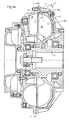
- Figures 1a and 1b illustrate in a schematically simplified Representation of the basic structure of a designed according to the invention hydrodynamic clutch 1, in particular with a turbo clutch Integrated synchronizer clutch 2 in two views.
- Figure 1a illustrates a view in a radial section while the figure 1b shows an embodiment in a view I - I according to FIG. 1a.
- the outer wheel 3 preferably functions as an impeller while the inner wheel 5 takes over the function of the turbine wheel.
- the External wheel 3 is used for this purpose in drive trains at least indirectly with the drive side, especially one Drive unit non-rotatably connected, while that, the turbine wheel inner wheel 5 is coupled to the driven side.
- the synchronizer clutch 2 is integrated in the hydrodynamic clutch 1 and comprises at least two frictionally operable Coupling elements, a first coupling element 6.1 and a second Coupling element 6.2. According to the coupling elements from the clutch shell 4 and the inner wheel 5 of the hydrodynamic Coupling formed.
- the inner wheel 5 forms the coupling element 6.1, and is designed according to the invention as a multi-part centrifugal body.
- the inner wheel 5 or the coupling element 6.1 is divided in the circumferential direction into at least two segments, which in their entirety when stored or guided on one Profile shaft or hub 7 at least under the influence of centrifugal force are movable in the radial direction.
- the division is preferably made in three individual segments 8.1, 8.2 and 8.3. Form the individual segments the structural unit when strung together in the circumferential direction Inner wheel 5 and are preferably in terms of their geometric Dimensions identical to each other.
- the inner wheel 5 in of a hydrodynamic coupling 1 torques are to be transmitted it is necessary that the inner wheel 5, in particular the individual segments viewed in the circumferential direction are at least guided such that a Driving function is guaranteed, while in the radial direction Movability under centrifugal force of the individual segments 8.1 to 8.3 given is.
- means are used to guide the individual Segments 8.1 to 8.3 are provided, which are usually of the profile shaft or hub 7 are formed. This is at least indirect - depending on Function of the inner wheel 5 - rotatably connected to the output side.
- the Profile shaft or hub 7 has a corresponding one Driver profile 9 on.
- the specific load that can be described by the performance indicator to reduce the mass of the flyweight must be kept as low as possible become.
- a relatively light material is preferably selected here, for example aluminum.
- this is usually not suitable for a friction connection, which is why a corresponding friction lining 13 on Outer circumference 12, in particular on the individual outer circumferences 12.1 to 12.3 of the individual segments 8.1 to 8.3 of the inner wheel 5 are provided become.
- a bronze coating is used as the friction lining, which either cast on the circumference of the inner wheel 5 or is sprayed on.
- the outer wheel 3 and the coupling with one Drive machine additionally an axial force on the inner wheel 5.
- a resource such as oil or water and rotation of the Pump wheel
- the outer wheel 3 and the coupling with one Drive machine additionally an axial force on the inner wheel 5.
- Zur Absorption of this axial force on the inner wheel 5, in particular the individual Segments 8.1 to 8.3 of the inner wheel 5 are corresponding means 14 for Absorption of the axial force provided.
- These are either from the Means for guiding 9, in particular the driver profile 9 on the Profile shaft or hub 7 formed or by means of one, not here additional guide 15 shown on the circumference of the Coupling shell 4 added.
- the means for absorbing the axial forces 14 are for receiving one acting in both directions Dimension axial force, since the axial force acts alternately.
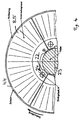
- FIG. 2 clarifies the attack of the forces during the transmission of forces, in a substantially abstracted form based on a view according to FIG. 1b on the inner wheel 5 of the hydrodynamic clutch 1, with area loads for clarification being assumed as point loads.
- the contact force F An which presses the inner wheel segments 8.1 to 8.3 onto the clutch shell 4, in particular in the region of the inner circumference 11 thereof, is exerted for the torque that can be transmitted by the friction due to the effect of the centrifugal force.
- this contact pressure F An consists of the centrifugal force F Flieh .
- the driver profile 9 is designed such that due to the hydrodynamic forces F hydr , which act essentially in the circumferential direction, and the design of the driver profile 9 on the inner circumference 17 of the inner wheel 5, in particular 17.1 to 17.3 on the segments 8.1 to 8.3, the profile shaft is entrained or hub 7 is achieved with a functional assignment of the function of the turbine wheel T to the inner wheel 5.
- the mutually engaging areas of the profile shaft or hub 7 and the individual segments 8.1 to 8.3 are designed in such a way that mobility in the circumferential direction around the shaft or hub is not permitted or is permitted only to a very limited extent, but furthermore the mobility of the individual segments 8.1 to 8.n in the radial direction is not impaired.
- the profile design on the inner wheel 5 or on the inner circumferences 17.1 to 17.3 of the individual segments 8.1 to 8.3 and complementary thereto on the profile shaft or profile hub 7 is carried out in such a way that it is designed symmetrically with respect to the line of symmetry of the inner segment.
- both profiles each have a flat surface area 18 or 19, which come into contact with each other, a stop being provided on both sides of this surface area, which is realized by the specific design of the inner wheel segment 8.1 to 8.3 or complementary to the hub.
- the profile shaft or hub 7 preferably has corresponding projections 20.1 to 20.3, with one projection 20.1 to 20.3 each in the recess 21.1.1 or 21.1.1 and 21.2.1 of two segments 8.1 and 8.2 adjacent to one another in the circumferential direction in the region of whose impact plane E S 8.1-8.2 engages.
- FIG. 3 shows, compared to one another, different start-up characteristics in the form of the start-up characteristic value ⁇ * 10 3 , which acts as a performance characteristic, as a function of the slip S occurring over the duration of the start-up process.
- the characteristic curve labeled A represents a characteristic curve for a conventional hydrodynamic clutch without synchronization, while the characteristic curve characterized by B only represents the characteristic curve for the friction component and C indicates the starting characteristic curve of a hydrodynamic clutch 1 with synchronous clutch 2 designed according to the invention. From this it can be seen that due to the synchronization effect in the area of low slip, in particular with a slip of ⁇ 10, a considerable increase in the starting value is achieved.
- FIG 4 illustrates a schematically highly simplified representation Another possibility of realizing a non-rotatable connection between the segments 8.4 of the inner wheel 5.4 by means of a connection for example, a bolt 22 which is between the hub 23 and a segment 8.4 of the inner wheel 8.5 forms a hinge 24.
- the Swivel 24 enables the segments 8.4 in to be carried along Circumferential direction and more centrifugal force a movement of Inner wheel segments 8.5, which are characterized by at least one component in can describe radial direction, so that a frictional connection between Inner wheel segment 8.4 and the clutch shell 4.4 is realized.
- the for this purpose, swivel joint 24 is in the radially inner region of the Inner wheel segment 8.4 and in the case shown in the direction of rotation viewed in the rear area of the inner wheel segment 8.5.
Landscapes
- Engineering & Computer Science (AREA)
- General Engineering & Computer Science (AREA)
- Mechanical Engineering (AREA)
- One-Way And Automatic Clutches, And Combinations Of Different Clutches (AREA)
- Mechanical Operated Clutches (AREA)
- Turbine Rotor Nozzle Sealing (AREA)
- Lubrication Of Internal Combustion Engines (AREA)
Description
- Fig. 1a und 1b
- verdeutlichen in schematisch vereinfachter Darstellung den Grundaufbau einer erfindungsgemäß gestalteten hydrodynamischen Kupplung mit integrierter Synchronkupplung;
- Fig. 2
- verdeutlicht in schematisch stark vereinfachter Darstellung eine Ausführung der Führung zwischen Innenradsegment und Führungselement;
- Fig. 3
- verdeutlicht einander gegenübergestellt die Kennlinien einer hydrodynamischen Kupplung ohne Synchronkupplung und einer hydrodynamischen Kupplung mit Synchronkupplung;
- Fig. 4
- verdeutlicht eine weitere Ausführung einer Führung zwischen Innenradsegment und Führungselement.
- P1 -
- übertragbare Leistung
- PFL -
- Anpreßdruck
- DP -
- Durchmesser am Außenumfang des Pumpenrades
- ω ′1, -
- Winkelgeschwindigkeit
- 1
- Hydrodynamische Kupplung
- 2
- Synchronkupplung
- 3
- Außenrad
- 4
- Kupplungsschale
- 5; 5.4
- Innenrad
- 6.1
- Erstes Kupplungselement
- 6.2
- Zweites Kupplungselement
- 7
- Profliwelle beziehungsweise Profilnabe
- 8
- Segmente des Innenrades
- 8.1 - 8.4
- Segmente des Innenrades
- 9
- Mittel zur Führung, insbesondere Mitnehmerprofil
- 10
- Torusförmiger Arbeitsraum
- 11
- Innenumfang der Kupplungsschale
- 12
- Außenumfang des Innenrades
- 12.1 - 12.3
- Außenumfang der Innenradsegmente 8.1 bis 8.3
- 13
- Reibbelag
- 14
- Mittel zur Aufnahme der Axialkräfte
- 15
- Führung
- 16
- Punkt
- 17
- Innenumfang
- 18
- Ebene Fläche
- 19
- Ebene Fläche
- 20.1 - 20.3
- Vorsprünge an der Profilwelle beziehungsweise Profilnabe 7
- 21.1.1
- Ausnehmungen
- 21.1.2
- Ausnehmungen
- 21.3.1
- Ausnehmungen
- 21.3.2
- Ausnehmungen
- 22
- Bolzen
- 23
- Nabe
- 24
- Drehgelenk
- ES 8.1-8.2
- Stoßebene
- λ * 103
- Leistungskennzahl, Anfahrkennwert
- FReib
- Reibungskraft
- Fhydr
- Hydrodynamische Kraft
- FAn
- Anpreßkraft
- PI
- Übertragbare Leistung
Claims (13)
- Hydrodynamische Kupplung (1)1.1 mit wenigstens zwei Schaufelrädern, einem Außenrad (3) und einem, von einer, mit dem Außenrad (3) gekoppelten Kupplungsschale (4) wenigstens teilweise umschlossenen Innenrad (5);1.2 mit einer Synchronkupplung (2), umfassend wenigstens zwei Kupplungselemente (6.1, 6.2), welche reibschlüssig wenigstens mittelbar miteinander in Wirkverbindung bringbar sind, wobei das zweite Kupplungselement von der Kupplungsschale (4) gebildet ist;
gekennzeichnet durch die folgenden Merkmale:1.3 das Innenrad (5) ist in wenigstens zwei Segmente (8.1, 8.2, 8.3) unterteilt, die in radialer Richtung verschiebbar gelagert und in Umfangsrichtung wenigstens in Rotationsrichtung wenigstens mittelbar drehfest mit der An- oder Abtriebsseite verbindbar sind;1.4 das erste Kupplungselement (6.1) wird von den Segmenten (8.1, 8.2, 8.3) des Innenrades (5) gebildet. - Hydrodynamische Kupplung (1) nach Anspruch 1, dadurch gekennzeichnet, daß die einzeinen Segmente (8.1, 8.2, 8.3) des Innenrades (5) hinsichtlich ihrer Form und der geometrischen Abmessungen identisch ausgeführt sind.
- Hydrodynamische Kupplung (1) nach einem der Ansprüche 1 oder 2, dadurch gekennzeichnet, daß die einzelnen Segmente (8.1, 8.2, 8.3) des Innenrades (5) mit wenigstens einem Teilbereich der durch ihren Außenumfang (12.1, 12.2, 12.3) charakterisierbaren Flächenbereiche mit Flächenbereichen am Innenumfang (11) der Kupplungsschale (4) eine Reibpaarung bilden.
- Hydrodynamische Kupplung (1) nach einem der Ansprüche 1 bis 3, dadurch gekennzeichnet, daß die Flächenbereiche am Außenumfang (12.1, 12.2, 12.3) der Segmente (8.1, 8.2, 8.3) und/oder am Innenumfang (11) der Kupplungsschale (4) mit einem Reibbelag versehen sind.
- Hydrodynamische Kupplung (1) nach Anspruch 4, dadurch gekennzeichnet, daß die Reibpaarung zwischen den Flächenbereichen am Außenumfang (12.1, 12.2, 12.3) der Segmente (8.1, 8.2, 8.3) und/oder am Innenumfang (11) der Kupplungsschale (4) von den gleichen Materialien gebildet wird.
- Hydrodynamische Kupplung (1) nach Anspruch 4, dadurch gekennzeichnet, daß die Reibpaarung zwischen den Flächenbereichen am Außenumfang (12.1, 12.2, 12.3) der Segmente (8.1, 8.2, 8.3) und/oder am Innenumfang (11) der Kupplungsschale (4) von unterschiedlichen Materialien gebildet wird.
- Hydrodynamische Kupplung (1) nach Anspruch 6, gekennzeichnet durch die folgenden Merkmale:7.1 die Kupplungsschale (4) ist im Bereich ihres Innenumfanges aus Sphäroguß gefertigt;7.2 die Segmente (8.1, 8.2, 8.3) sind aus Aluminium gefertigt und im Bereich ihres Außenumfanges (12.1, 12.2, 12.3) mit Bronze beschichtet.
- Hydrodynamische Kupplung (1) nach einem der Ansprüche 1 bis 7, gekennzeichnet durch die folgenden Merkmale:8.1 zur radialen Bewegbarkeit und Drehmomentübertragung in Umfangsrichtung sind den Segmenten (8.1, 8.2, 8.3) des Innenrades (5) Mittel zur Führung (9) zugeordnet;8.2 die Mittel zur Führung (9) umfassen wenigstens eine, mit einem Mitnehmerprofil versehene Profilwelle und/oder -nabe (7), welche mit einem dazu komplementären Profil an den einzelnen Segmenten (8.1, 8.2, 8.3) einen Formschluß in Umfangsrichtung ermöglichen.
- Hydrodynamische Kupplung (1) nach Anspruch 8, dadurch gekennzeichnet, daß der Formschluß in Umfangsrichtung ohne Radialkrafteinfluß ist.
- Hydrodynamische Kupplung (1) nach einem der Ansprüche 8 oder 9, gekennzeichnet durch die folgenden Merkmale:10.1 das Innenrad (5) ist in drei Segmente (8.1, 8.2, 8.3) unterteilt;10.2 die Mittel zur Führung (9) umfassen eine Profilwelle oder Profilnabe (7), welche einen dreieckigen Querschnitt aufweist, der durch drei Vorsprünge (20.1, 20.2, 20.3) charakterisiert ist;10.3 die Vorsprünge (20.1, 20.2, 20.3) greifen in dazu komplementäre Ausnehmungen zweier in Umfangsrichtung einander benachbarter Segmente (8.1 und 8.2) im Bereich von deren Stoßebene ES 8.1-8.2 ein.
- Hydrodynamische Kupplung (1) nach einem der Ansprüche 1 bis 10, dadurch gekennzeichnet, daß Mittel zur Kompensation der bei der hydrodynamischen Leistungsübertragung auftretenden Axialkräfte (14) vorgesehen sind.
- Hydrodynamische Kupplung (1) nach Anspruch 11, dadurch gekennzeichnet, daß die Mittel zur Aufnahme der Axialkräfte (14) Anschläge im Bereich des Innenumfanges des Innenrades (5) umfassen.
- Hydrodynamische Kupplung (1) nach Anspruch 11 oder 12, dadurch gekennzeichnet, daß die Mittel Anschläge am Innenumfang (11) der Kupplungsschale (4) umfassen.
Applications Claiming Priority (3)
| Application Number | Priority Date | Filing Date | Title |
|---|---|---|---|
| DE19942578 | 1999-09-07 | ||
| DE19942578A DE19942578C2 (de) | 1999-09-07 | 1999-09-07 | Hydrodynamische Kupplung |
| PCT/EP2000/008705 WO2001018429A1 (de) | 1999-09-07 | 2000-09-06 | Hydrodynamische kupplung |
Publications (2)
| Publication Number | Publication Date |
|---|---|
| EP1127231A1 EP1127231A1 (de) | 2001-08-29 |
| EP1127231B1 true EP1127231B1 (de) | 2003-06-04 |
Family
ID=7921036
Family Applications (1)
| Application Number | Title | Priority Date | Filing Date |
|---|---|---|---|
| EP00960615A Expired - Lifetime EP1127231B1 (de) | 1999-09-07 | 2000-09-06 | Hydrodynamische kupplung |
Country Status (8)
| Country | Link |
|---|---|
| US (1) | US6502678B1 (de) |
| EP (1) | EP1127231B1 (de) |
| JP (1) | JP2003508708A (de) |
| AT (1) | ATE242441T1 (de) |
| BR (1) | BR0007216B1 (de) |
| DE (2) | DE19942578C2 (de) |
| ES (1) | ES2194772T3 (de) |
| WO (1) | WO2001018429A1 (de) |
Cited By (1)
| Publication number | Priority date | Publication date | Assignee | Title |
|---|---|---|---|---|
| DE102019125894A1 (de) * | 2019-09-26 | 2021-04-01 | Voith Patent Gmbh | Hydrodynamische Maschine, insbesondere hydrodynamische Kupplung |
Families Citing this family (6)
| Publication number | Priority date | Publication date | Assignee | Title |
|---|---|---|---|---|
| DE10039811A1 (de) * | 2000-08-16 | 2002-03-07 | Voith Turbo Kg | Hydrodynamischer Wandler |
| DE10210992A1 (de) * | 2002-03-13 | 2003-10-02 | Zahnradfabrik Friedrichshafen | Schaltelement für drehende Teile |
| DE102006017975B3 (de) * | 2006-04-13 | 2007-08-23 | Voith Turbo Gmbh & Co. Kg | Hydrodynamische Kupplung |
| DE102007005661A1 (de) | 2007-01-31 | 2008-08-07 | Voith Patent Gmbh | Maschinensatz mit einem Antrieb und einer Arbeitsmaschine |
| DE102007047889A1 (de) * | 2007-11-29 | 2009-06-04 | Zf Friedrichshafen Ag | Lagerung der Rotorwelle eines hydrodynamischen Retarders |
| EP2930320A1 (de) * | 2014-04-07 | 2015-10-14 | Siemens Aktiengesellschaft | Verfahren zum Betreiben einer Dampfturbine |
Family Cites Families (22)
| Publication number | Priority date | Publication date | Assignee | Title |
|---|---|---|---|---|
| DE374259C (de) * | 1919-05-09 | 1923-04-21 | Hermann Foettinger Dr Ing | Vereinigte Asynchronkupplung und Synchronkupplung |
| DE479119C (de) * | 1927-07-02 | 1929-07-09 | Hermann Foettinger Dr Ing | Einrichtung zum Betrieb von hydraulischen Verbundkupplungen |
| US2055300A (en) * | 1934-01-19 | 1936-09-22 | Chrysler Corp | Clutch |
| US2034757A (en) * | 1934-01-19 | 1936-03-24 | Chrysler Corp | Clutch |
| FR831078A (fr) | 1936-12-24 | 1938-08-22 | Deutsche Schiff & Maschb Ag | Embrayage hydraulique, à glissement et à prise rigide |
| US2380734A (en) * | 1941-12-16 | 1945-07-31 | John W Hurley | Hydraulic transmission |
| US2613782A (en) * | 1945-02-19 | 1952-10-14 | Chrysler Corp | Synchronized centrifugal clutch |
| US3519112A (en) * | 1968-03-13 | 1970-07-07 | Sergio Verzolla | Fluid coupling with centrifugal roller lock-up clutch |
| DE1775184B1 (de) * | 1968-03-13 | 1971-09-30 | Sergio Verzolla | Hydrodynamische kupplung mit einer fliehkraftbetaetigten reibungskupplung zum ueberbruecken des hydrodynamischen arbeitskreises |
| FR2166464A5 (de) | 1971-11-26 | 1973-08-17 | Lefort Philippe | |
| JPS5217754B2 (de) * | 1971-12-27 | 1977-05-17 | ||
| DE2245901A1 (de) * | 1972-09-19 | 1974-04-04 | Konrad Altmann | Vorrichtung zum stufenlosen uebertragen eines drehmomentes |
| US4037691A (en) * | 1976-01-02 | 1977-07-26 | Borg-Warner Corporation | Centrifugal lock up clutch for fluid couplings |
| US4140210A (en) * | 1977-05-12 | 1979-02-20 | Borg-Warner Corporation | Centrifugally and torque engaged clutch |
| US4113075A (en) * | 1977-05-20 | 1978-09-12 | General Motors Corporation | Centrifugal lock-up clutch and torque converter |
| US4586594A (en) * | 1981-05-14 | 1986-05-06 | Voith Turbo Gmbh & Co. Kg | Clutch assembly capable of being engaged by fluid pressure depending on centrifugal force |
| DE3409690C1 (de) | 1984-03-16 | 1985-09-12 | Daimler-Benz Ag, 7000 Stuttgart | Kupplungsanordnung eines Antriebsaggregates eines Fahrzeuges mit einer hydrodynamischen Strömungskupplung und einer Reibkupplung |
| JPS6131731A (ja) | 1984-07-20 | 1986-02-14 | N S K Warner Kk | 速度応答型遠心クラツチ |
| JPS61131537U (de) * | 1985-02-05 | 1986-08-16 | ||
| JP2784035B2 (ja) * | 1989-04-12 | 1998-08-06 | エヌエスケー・ワーナー株式会社 | 速度応答型一方向遠心クラッチ |
| DE3917986C1 (en) * | 1989-06-02 | 1990-08-02 | Deutsche Automobilgesellschaft Mbh, 3000 Hannover, De | Centrifugal bridging clutch for hydrodynamic torque converters - has resetting spring assemblies with temp.-dependent operation, with increased rigidity at temp. reduction |
| DE4444242B4 (de) * | 1993-12-23 | 2004-07-08 | Volkswagen Ag | Kupplungsanordnung für ein Kraftfahrzeug |
-
1999
- 1999-09-07 DE DE19942578A patent/DE19942578C2/de not_active Expired - Fee Related
-
2000
- 2000-09-06 US US09/831,324 patent/US6502678B1/en not_active Expired - Lifetime
- 2000-09-06 BR BRPI0007216-8A patent/BR0007216B1/pt not_active IP Right Cessation
- 2000-09-06 WO PCT/EP2000/008705 patent/WO2001018429A1/de not_active Ceased
- 2000-09-06 AT AT00960615T patent/ATE242441T1/de not_active IP Right Cessation
- 2000-09-06 DE DE50002437T patent/DE50002437D1/de not_active Expired - Lifetime
- 2000-09-06 EP EP00960615A patent/EP1127231B1/de not_active Expired - Lifetime
- 2000-09-06 JP JP2001521929A patent/JP2003508708A/ja active Pending
- 2000-09-06 ES ES00960615T patent/ES2194772T3/es not_active Expired - Lifetime
Cited By (1)
| Publication number | Priority date | Publication date | Assignee | Title |
|---|---|---|---|---|
| DE102019125894A1 (de) * | 2019-09-26 | 2021-04-01 | Voith Patent Gmbh | Hydrodynamische Maschine, insbesondere hydrodynamische Kupplung |
Also Published As
| Publication number | Publication date |
|---|---|
| DE19942578C2 (de) | 2001-11-15 |
| WO2001018429A1 (de) | 2001-03-15 |
| EP1127231A1 (de) | 2001-08-29 |
| ES2194772T3 (es) | 2003-12-01 |
| DE19942578A1 (de) | 2001-04-12 |
| JP2003508708A (ja) | 2003-03-04 |
| US6502678B1 (en) | 2003-01-07 |
| BR0007216B1 (pt) | 2008-11-18 |
| DE50002437D1 (de) | 2003-07-10 |
| ATE242441T1 (de) | 2003-06-15 |
| BR0007216A (pt) | 2001-07-31 |
Similar Documents
| Publication | Publication Date | Title |
|---|---|---|
| DE19804227B4 (de) | Überbrückungskupplung mit einer Ausgleichsschwungmasse am Torsionsschwingungsdämpfer | |
| DE102008006581B4 (de) | Drehmoment übertragende Anordnung mit Klauenkupplung und hydrostatischem Dämpfer | |
| EP2470808B1 (de) | Doppelkupplungsanordnung für ein getriebe mit zwei eingangswellen | |
| EP2494224B1 (de) | Kupplung mit vorkupplung und hauptkupplung | |
| DE102008031010A1 (de) | Zwei-Kanal Mehrfunktionsdrehmomentwandler | |
| EP2268934B1 (de) | Kupplungsanordnung, insbesondere für den antriebsstrang eines fahrzeugs | |
| EP2475908A1 (de) | Synchronisationseinheit eines getriebes | |
| DE1575925B1 (de) | Hydraulisch betaetigbare Scheiben-Reibungskupplung,insbesondere Doppelkupplung | |
| DE2263835B2 (de) | Hydrodynamischer drehmomentwandler mit schaltbarer reibungstrennkupplung | |
| EP0088150A2 (de) | Unter Last schaltbare mechanische Getriebeanordnung | |
| DE19932576B4 (de) | Hydrodynamischer Drehmomentwandler | |
| EP1726842B1 (de) | Kupplungsanordnung in radial geschachtelter Bauart | |
| EP1127231B1 (de) | Hydrodynamische kupplung | |
| CH390007A (de) | Selbsteinrückende Synchronzahnkupplung | |
| DE4433256A1 (de) | Drehmomentwandler | |
| DE60124200T2 (de) | Leistungsübertragungsvorrichtung mit Drehmomentwandler | |
| DE2236832C3 (de) | ||
| DE4424988C1 (de) | Hydrodynamischer Drehmomentwandler mit einer Überbrückungskupplung | |
| DE3409692A1 (de) | Antriebsanordnung eines kraftfahrzeuges mit einer hydrodynamischen stroemungskupplung und einem von hand schaltbaren gangwechselgetriebe | |
| DE10039813C1 (de) | Maschinensatz mit einem Antrieb und einer Arbeitsmaschine | |
| DE10050729A1 (de) | Hydrodynamische Kopplungseinrichtung | |
| DE102007005661A1 (de) | Maschinensatz mit einem Antrieb und einer Arbeitsmaschine | |
| DE10004952C2 (de) | Überbrückungsvorrichtung für einen Drehmomentwandler | |
| DE19848584A1 (de) | Selbstverstärkende Reibungskupplung | |
| DE1425358B2 (de) | Hydraulisch betaetigbare scheibenreibungskupplung |
Legal Events
| Date | Code | Title | Description |
|---|---|---|---|
| PUAI | Public reference made under article 153(3) epc to a published international application that has entered the european phase |
Free format text: ORIGINAL CODE: 0009012 |
|
| 17P | Request for examination filed |
Effective date: 20010426 |
|
| AK | Designated contracting states |
Kind code of ref document: A1 Designated state(s): AT BE CH CY DE DK ES FI FR GB GR IE IT LI LU MC NL PT SE |
|
| GRAH | Despatch of communication of intention to grant a patent |
Free format text: ORIGINAL CODE: EPIDOS IGRA |
|
| GRAH | Despatch of communication of intention to grant a patent |
Free format text: ORIGINAL CODE: EPIDOS IGRA |
|
| GRAA | (expected) grant |
Free format text: ORIGINAL CODE: 0009210 |
|
| AK | Designated contracting states |
Designated state(s): AT BE CH CY DE DK ES FI FR GB GR IE IT LI LU MC NL PT SE |
|
| PG25 | Lapsed in a contracting state [announced via postgrant information from national office to epo] |
Ref country code: NL Free format text: LAPSE BECAUSE OF FAILURE TO SUBMIT A TRANSLATION OF THE DESCRIPTION OR TO PAY THE FEE WITHIN THE PRESCRIBED TIME-LIMIT Effective date: 20030604 Ref country code: FI Free format text: LAPSE BECAUSE OF FAILURE TO SUBMIT A TRANSLATION OF THE DESCRIPTION OR TO PAY THE FEE WITHIN THE PRESCRIBED TIME-LIMIT Effective date: 20030604 Ref country code: IE Free format text: LAPSE BECAUSE OF FAILURE TO SUBMIT A TRANSLATION OF THE DESCRIPTION OR TO PAY THE FEE WITHIN THE PRESCRIBED TIME-LIMIT Effective date: 20030604 |
|
| REG | Reference to a national code |
Ref country code: GB Ref legal event code: FG4D Free format text: NOT ENGLISH |
|
| REG | Reference to a national code |
Ref country code: CH Ref legal event code: EP |
|
| GBT | Gb: translation of ep patent filed (gb section 77(6)(a)/1977) | ||
| REG | Reference to a national code |
Ref country code: IE Ref legal event code: FG4D Free format text: GERMAN |
|
| REF | Corresponds to: |
Ref document number: 50002437 Country of ref document: DE Date of ref document: 20030710 Kind code of ref document: P |
|
| PG25 | Lapsed in a contracting state [announced via postgrant information from national office to epo] |
Ref country code: SE Free format text: LAPSE BECAUSE OF FAILURE TO SUBMIT A TRANSLATION OF THE DESCRIPTION OR TO PAY THE FEE WITHIN THE PRESCRIBED TIME-LIMIT Effective date: 20030904 Ref country code: GR Free format text: LAPSE BECAUSE OF FAILURE TO SUBMIT A TRANSLATION OF THE DESCRIPTION OR TO PAY THE FEE WITHIN THE PRESCRIBED TIME-LIMIT Effective date: 20030904 Ref country code: PT Free format text: LAPSE BECAUSE OF FAILURE TO SUBMIT A TRANSLATION OF THE DESCRIPTION OR TO PAY THE FEE WITHIN THE PRESCRIBED TIME-LIMIT Effective date: 20030904 Ref country code: DK Free format text: LAPSE BECAUSE OF FAILURE TO SUBMIT A TRANSLATION OF THE DESCRIPTION OR TO PAY THE FEE WITHIN THE PRESCRIBED TIME-LIMIT Effective date: 20030904 |
|
| PG25 | Lapsed in a contracting state [announced via postgrant information from national office to epo] |
Ref country code: AT Free format text: LAPSE BECAUSE OF NON-PAYMENT OF DUE FEES Effective date: 20030906 Ref country code: LU Free format text: LAPSE BECAUSE OF NON-PAYMENT OF DUE FEES Effective date: 20030906 Ref country code: CY Free format text: LAPSE BECAUSE OF FAILURE TO SUBMIT A TRANSLATION OF THE DESCRIPTION OR TO PAY THE FEE WITHIN THE PRESCRIBED TIME-LIMIT Effective date: 20030906 |
|
| PG25 | Lapsed in a contracting state [announced via postgrant information from national office to epo] |
Ref country code: BE Free format text: LAPSE BECAUSE OF NON-PAYMENT OF DUE FEES Effective date: 20030930 Ref country code: MC Free format text: LAPSE BECAUSE OF NON-PAYMENT OF DUE FEES Effective date: 20030930 |
|
| NLV1 | Nl: lapsed or annulled due to failure to fulfill the requirements of art. 29p and 29m of the patents act | ||
| REG | Reference to a national code |
Ref country code: IE Ref legal event code: FD4D |
|
| BERE | Be: lapsed |
Owner name: *VOITH TURBO G.M.B.H. & CO. K.G. Effective date: 20030930 |
|
| ET | Fr: translation filed | ||
| PLBE | No opposition filed within time limit |
Free format text: ORIGINAL CODE: 0009261 |
|
| STAA | Information on the status of an ep patent application or granted ep patent |
Free format text: STATUS: NO OPPOSITION FILED WITHIN TIME LIMIT |
|
| 26N | No opposition filed |
Effective date: 20040305 |
|
| PG25 | Lapsed in a contracting state [announced via postgrant information from national office to epo] |
Ref country code: CH Free format text: LAPSE BECAUSE OF NON-PAYMENT OF DUE FEES Effective date: 20040930 Ref country code: LI Free format text: LAPSE BECAUSE OF NON-PAYMENT OF DUE FEES Effective date: 20040930 |
|
| REG | Reference to a national code |
Ref country code: CH Ref legal event code: PL |
|
| REG | Reference to a national code |
Ref country code: FR Ref legal event code: PLFP Year of fee payment: 17 |
|
| PGFP | Annual fee paid to national office [announced via postgrant information from national office to epo] |
Ref country code: GB Payment date: 20160920 Year of fee payment: 17 |
|
| PGFP | Annual fee paid to national office [announced via postgrant information from national office to epo] |
Ref country code: FR Payment date: 20160921 Year of fee payment: 17 |
|
| PGFP | Annual fee paid to national office [announced via postgrant information from national office to epo] |
Ref country code: ES Payment date: 20160916 Year of fee payment: 17 |
|
| PGFP | Annual fee paid to national office [announced via postgrant information from national office to epo] |
Ref country code: DE Payment date: 20170928 Year of fee payment: 18 Ref country code: IT Payment date: 20170926 Year of fee payment: 18 |
|
| GBPC | Gb: european patent ceased through non-payment of renewal fee |
Effective date: 20170906 |
|
| REG | Reference to a national code |
Ref country code: FR Ref legal event code: ST Effective date: 20180531 |
|
| PG25 | Lapsed in a contracting state [announced via postgrant information from national office to epo] |
Ref country code: GB Free format text: LAPSE BECAUSE OF NON-PAYMENT OF DUE FEES Effective date: 20170906 |
|
| PG25 | Lapsed in a contracting state [announced via postgrant information from national office to epo] |
Ref country code: FR Free format text: LAPSE BECAUSE OF NON-PAYMENT OF DUE FEES Effective date: 20171002 |
|
| REG | Reference to a national code |
Ref country code: ES Ref legal event code: FD2A Effective date: 20181019 |
|
| PG25 | Lapsed in a contracting state [announced via postgrant information from national office to epo] |
Ref country code: ES Free format text: LAPSE BECAUSE OF NON-PAYMENT OF DUE FEES Effective date: 20170907 |
|
| REG | Reference to a national code |
Ref country code: DE Ref legal event code: R119 Ref document number: 50002437 Country of ref document: DE |
|
| PG25 | Lapsed in a contracting state [announced via postgrant information from national office to epo] |
Ref country code: DE Free format text: LAPSE BECAUSE OF NON-PAYMENT OF DUE FEES Effective date: 20190402 Ref country code: IT Free format text: LAPSE BECAUSE OF NON-PAYMENT OF DUE FEES Effective date: 20180906 |