EP1127516B1 - Chaise pliable - Google Patents
Chaise pliable Download PDFInfo
- Publication number
- EP1127516B1 EP1127516B1 EP00306998A EP00306998A EP1127516B1 EP 1127516 B1 EP1127516 B1 EP 1127516B1 EP 00306998 A EP00306998 A EP 00306998A EP 00306998 A EP00306998 A EP 00306998A EP 1127516 B1 EP1127516 B1 EP 1127516B1
- Authority
- EP
- European Patent Office
- Prior art keywords
- chair
- locking
- frame
- locking member
- seat panel
- Prior art date
- Legal status (The legal status is an assumption and is not a legal conclusion. Google has not performed a legal analysis and makes no representation as to the accuracy of the status listed.)
- Expired - Lifetime
Links
- 230000015572 biosynthetic process Effects 0.000 claims description 11
- 230000005484 gravity Effects 0.000 claims description 4
- 210000001364 upper extremity Anatomy 0.000 claims description 4
- 230000004048 modification Effects 0.000 description 2
- 238000012986 modification Methods 0.000 description 2
- 229910000639 Spring steel Inorganic materials 0.000 description 1
- 208000027418 Wounds and injury Diseases 0.000 description 1
- 230000006378 damage Effects 0.000 description 1
- 230000001419 dependent effect Effects 0.000 description 1
- 230000003203 everyday effect Effects 0.000 description 1
- 208000014674 injury Diseases 0.000 description 1
Images



Classifications
-
- A—HUMAN NECESSITIES
- A47—FURNITURE; DOMESTIC ARTICLES OR APPLIANCES; COFFEE MILLS; SPICE MILLS; SUCTION CLEANERS IN GENERAL
- A47C—CHAIRS; SOFAS; BEDS
- A47C4/00—Foldable, collapsible or dismountable chairs
- A47C4/04—Folding chairs with inflexible seats
- A47C4/18—Folding chairs with inflexible seats having a frame made of metal
- A47C4/20—Folding chairs with inflexible seats having a frame made of metal with legs pivotably connected to seat or underframe
- A47C4/24—Folding chairs with inflexible seats having a frame made of metal with legs pivotably connected to seat or underframe with cross legs
Definitions
- This invention relates to a folding chair of the type comprising a pair of leg frames that are hinged together so that the chair may be folded substantially flat when not in use.
- a seat panel has one end hinged to one of the frames with the opposite end supported by the other frame when the chair is open for use.
- a seat panel and back support are hinged together to form a seat assembly that may be folded substantially flat, and the seat assembly is supported by the pair of leg frames.
- chairs of this type are inevitably prone to collapse during use. This can cause serious bodily injury. Additionally, the chair often collapses when it is lifted to be moved to another location. This is naturally inconvenient. Therefore, the aim of the invention is to realise a folding chair offering improved safety and/or convenience to the user.
- a folding chair comprises a first frame that forms the rear legs of the chair and a second frame that forms the front legs of the chair, the first and second frames being pivotally connected so as to enable the chair to be folded substantially flat when not in use, and further comprises a seat panel that has one end pivotally connected to one of the frames and an opposite end engagable with the other of the frames whereby said other frame supports said opposite end of the seat panel when the chair is open for use.
- the chair is characterized in that a locking member is mounted on one of said other frame and said opposite end of the seat panel for limited movement relative thereto, and the other of said other frame and said opposite end of the seat panel includes a locking formation for receiving the locking member to lock the chair in the open condition, the limited movement of the locking member enabling the locking member to assume a locking position in which the locking member is located within the locking formation, and a release position in which the locking member is located outside the locking formation.
- the arrangement is such that the locking member automatically assumes the locking position in the action of opening the chair whereas the locking member must be manually moved into the release position in order to unlock and fold the chair.
- the folding chair of this first aspect of the invention incorporates a highly effective and safe locking mechanism whose operation is not dependent on the user remembering to lock the chair and which has a low probability of being accidentally released while the chair is in use.
- the locking member comprises a bar extending laterally across the width of the chair, and the locking formation comprises a groove or notch adapted to locate an edge of the bar.
- the opposite ends of the bar may be loosely trapped in respective recesses of a shape which permits movement of the bar between the locking position and the release position. These recesses may have a substantially triangular shape whereby the bar rests against one inclined side of the triangle in the locking position.
- the locking member is preferably biased into the locking position.
- the bias may arise under the action of gravity on the locking member or under the action of resilient means such as at least one spring element, or both.
- the locking member may be temporarily and automatically displaced from its bias position into the release position before being returned, by virtue of the biasing action, into the locking position in which the locking member engages the locking formation.
- the seat panel is hinged to the second frame that forms the front legs of the chair.
- the locking member is mounted on the seat panel and the locking formation is formed at the end of the first frame that forms the rear legs of the chair and supports the front edge of the seat panel.
- the first frame may engage the seat panel by means of pins that extend outwardly from the frame and slide within respective grooves formed at each side of the seat panel.
- the seat panel may be hinged to the first frame that forms the rear legs of the chair.
- the locking member is mounted on the second frame that forms the front legs of the chair and the locking formation is formed at the rear edge of the seat panel. The rear end of the seat panel is supported by the second frame when the chair is open for use.
- the folding chair does not collapse when lifted up to be moved to a new location. This adds to the chair's convenience in everyday use.
- Figs 1 to 8 relate to a folding chair according to a first embodiment of the invention, wherein:
- Fig. 1 shows the chair in its open condition and Fig. 2 in its closed or folded state.
- the chair comprises a pair of leg frames 1, 2 which are coupled together by means of a pivot connection, such as a hinge, at a point remote from the ends of the frames.
- the first leg frame 1 forms the rear legs of the chair and the second frame 2 forms the forward legs of the chair.
- the second frame 2 also extends upwardly to form the back support of the chair.
- the back of the seat panel 3 is pivotally connected by means of a hinge to the second frame 2.
- the front of the seat panel 3 is supported by the upper end of the first frame 1 when the chair is open for use.
- Figs. 3 to 5 illustrate how the rear leg frame 1 is coupled to the seat panel.
- the frame 1 comprises a pair of mutually parallel side members 5 that form the rearwardly extending legs.
- the side members 5 are connected together by a pair of cross bars 6.
- the upper ends of the side members 5 include respective laterally outwardly extending pins 7, each of which may take the form of a screw or cylindrical stud or the like.
- the seat panel 3 comprises a seating board 8 and a pair of side timbers 9.
- the inward faces of the side timbers 9 include a groove 11 that extends substantially the length of the side timber 9.
- the pins 7 of the leg frame 1 ride in the respective grooves 11 of the seat panel as the chair is opened and closed.
- the pins 7 reside in the leftmost ends of the grooves 11, as viewed in Fig. 5.
- the pins 7 are located at the rightmost ends of the grooves 11, as viewed in Fig. 5.
- the chair is closed by lifting the front edge of the seat panel 3 upwardly and moving the same in the direction of the arrow 4 shown in Fig. 1.
- the shorter frame 1 rides in the grooves 11 of the seat panel as the frames 1 and 2 close together in a scissors-like action.
- the locking mechanism in this embodiment comprises a locking bar 10 which is mounted on the underside of the seat panel towards the front edge thereof.
- the locking bar 10 In the locked condition, the locking bar 10 is located in notches 15 formed in the upper edges of the side members 5 of the shorter leg frame 1.
- the locking bar 10 extends laterally across the width of the seat panel. Its ends are located loosely in substantially triangular-shaped recesses 12 formed in the side members 9 of the seat panel.
- the locking bar is biased into the locking position shown in Figs. 5 and 6 under the action of gravity, as represented by the arrow 13 in Fig. 6. In this state, the locking bar rests on the inclined edges of the triangular recesses 12.
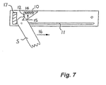
- the leg frame members 5 slide along the grooves 11 in the seat panel, moving in the left direction as viewed in Figs. 5 to 7.
- the locking bar 10 is temporarily moved upwardly being dislodged by the upper ends of the frame members 5.
- the locking bar 10 drops down to the locking position in which the lower edge of the locking bar is located within the triangular notch 15 of each frame member 5.
- the chair is now in the locked condition shown in Fig. 6.
- the leg frame 1 is prevented from moving upwardly by the location of the pins 7 at the ends of the grooves 11 and to the left by the stop block 17.
- the user In order to close the chair, the user must temporarily dislodge the locking bar 10 from the notches 15 by moving the locking bar 10 into the release position, as shown by the arrow 14 in Fig. 7.
- the leg frame members 5 are then free to travel along the groove 11 to close the chair. Once the upper ends of the frame members 5 have passed the locking bar 10, the latter will drop back under the action of gravity to the bias position shown in Fig. 5.
- Fig 8 shows a modification of the locking mechanism in which resilient means are employed to bias the locking bar into the locking position.
- an angled plate 18 formed of spring steel sheet is mounted at each end of the locking bar 10.
- the plate 18 may be secured to the locking bar by means of one or more screws.
- Each plate 18 is arranged as shown whereby the bar 10 is moved to the release position against the spring action and returns to the biased position upon release.
- the invention may be embodied in numerous other ways without departing from the scope thereof.
- the upper edge of the bar may be pivotally connected to the leg frame or seat panel.
- the movement of the locking bar between the locking and release positions may then be controlled by means of suitably positioned stopping members.
- the second frame extends upwardly to form a back support for the chair.
- the principles of the invention are applicable equally to a chair in the form of a stool which has no back support.
- a chair in accordance with an aspect of the invention may also incorporate arm rests that are hinged to one or more of the leg frames, seat panel and/or back support in a manner that is known per se in the art.
Landscapes
- Chairs For Special Purposes, Such As Reclining Chairs (AREA)
- Air Bags (AREA)
- Dry Shavers And Clippers (AREA)
- Pharmaceuticals Containing Other Organic And Inorganic Compounds (AREA)
Claims (8)
- Chaise pliante comprenant un premier châssis (1) qui forme les pieds arrières de la chaise et un second châssis (2) qui forme les pieds avant de la chaise, les premier et second châssis (1, 2) étant reliés d'une manière pivotante pour permettre que la chaise soit repliée sensiblement à plat lorsqu'elle n'est pas utilisée, et comprenant en outre une plaque de siège (3) dont une extrémité est reliée d'une manière pivotante à l'un desdits châssis et dont l'extrémité opposée peut être mise en prise avec l'autre desdits châssis, par quoi l'autre châssis précité supporte ladite extrémité opposée de la plaque de siège, lorsque la chaise est dépliée pour l'utilisation, caractérisée en ce qu'un élément de verrouillage (10) est monté sur l'un parmi l'autre châssis précité et ladite extrémité opposée de la plaque de siège en vue d'un déplacement limité relativement à celui-ci, et l'autre dudit autre châssis et de ladite extrémité opposée de la plaque de siège comporte une formation de verrouillage (15) pour recevoir ledit élément de verrouillage (10) pour bloquer la chaise à l'état ouvert, ledit déplacement limité de l'élément de verrouillage permettant à l'élément de verrouillage d'occuper une position de verrouillage dans laquelle l'élément de verrouillage (10) se situe dans la formation de verrouillage (15), et une position de libération dans laquelle l'élément de verrouillage se situe à l'extérieur de la formation de verrouillage, l'agencement étant tel que l'élément de verrouillage (10) occupe automatiquement la position de verrouillage lors de l'action d'ouverture de la chaise tandis que l'élément de verrouillage doit être amené manuellement dans la position de libération pour déverrouiller et plier la chaise.
- Chaise pliante selon la revendi cation 1, où ledit élément de verrouillage comprend une barre (10) s'étendant latéralement sur la largeur de la chaise, et ladite formation de verrouillage comprend une rainure ou encoche (15) apte à localiser un bord de ladite barre.
- Chaise pliante s elon la revendication 2, où les extrémités opposées de ladite barre (10) sont retenues lâchement dans des évidements respectifs (12) d'une forme qui permet un mouvement de la barre entre ladite position de verrouillage et ladite position de relâchement.
- Chaise pliante selon la revendication 3, où chacun desdits évidements (12) a une forme sensiblement triangulaire, et ladite barre (10) est adjacente à un côté du triangle dans ladite position de verrouillage.
- Chaise pliante selon l'une des revendications 1 à 4, où ledit élément de verrouillage (10) est sollicité dans ladite position de verrouillage sous l'effet de la gravité.
- Chaise pliante selon l'une des revendications 1 à 4, où ledit élément de verrouillage (10) est sollicité dans ladite position de verrouillage sous l'action d'un moyen élastique (18).
- Chaise pliante selon l'une des revendications 1 à 6, où ledit autre châssis (1) vient en prise avec ledit panneau de siège (3) au moyen d'axes (7) qui s'étendent latéralement vers l'extérieur depuis le châssis (1) et qui coulissent dans des rainures respectives (11) ménagées à chaque côté (9) de ladite plaque de siège.
- Chaise pliante selon la revendication 7, où ledit premier châssis (1) constitue ledit autre châssis.
Applications Claiming Priority (2)
| Application Number | Priority Date | Filing Date | Title |
|---|---|---|---|
| MYPI20000751 | 2000-02-28 | ||
| MY0000751 | 2000-02-28 |
Publications (2)
| Publication Number | Publication Date |
|---|---|
| EP1127516A1 EP1127516A1 (fr) | 2001-08-29 |
| EP1127516B1 true EP1127516B1 (fr) | 2004-10-27 |
Family
ID=19749447
Family Applications (1)
| Application Number | Title | Priority Date | Filing Date |
|---|---|---|---|
| EP00306998A Expired - Lifetime EP1127516B1 (fr) | 2000-02-28 | 2000-08-16 | Chaise pliable |
Country Status (5)
| Country | Link |
|---|---|
| EP (1) | EP1127516B1 (fr) |
| AT (1) | ATE280524T1 (fr) |
| AU (1) | AU3632401A (fr) |
| DE (1) | DE60015290T2 (fr) |
| WO (1) | WO2001064077A2 (fr) |
Cited By (1)
| Publication number | Priority date | Publication date | Assignee | Title |
|---|---|---|---|---|
| DE102016000996A1 (de) | 2016-01-29 | 2017-08-03 | Maximilian von Moszczenski | Klappstuhl mit Verstellung der Sitzwinkel im Upcycling hergestellt. |
Families Citing this family (5)
| Publication number | Priority date | Publication date | Assignee | Title |
|---|---|---|---|---|
| CA2479101A1 (fr) * | 2002-03-12 | 2003-09-18 | Shing Chi Tsang | Chaise pliante compacte |
| US7080877B1 (en) | 2004-10-29 | 2006-07-25 | Maxchief Investments, Ltd | Folding chair with sliding leg structure |
| USD802954S1 (en) | 2015-05-03 | 2017-11-21 | Zhuhai Shichang Metals, Ltd. | Foldable chair |
| US11103071B2 (en) * | 2018-06-11 | 2021-08-31 | Zhejiang Hengfeng Top Leisure Co., Ltd | Collapsible chair |
| CN222264810U (zh) * | 2024-03-27 | 2024-12-31 | 厦门新技术集成有限公司 | 一种使用安全的折叠椅 |
Family Cites Families (8)
| Publication number | Priority date | Publication date | Assignee | Title |
|---|---|---|---|---|
| US2294340A (en) * | 1938-08-17 | 1942-08-25 | Acme Chair Company | Folding chair |
| US2828805A (en) * | 1955-12-05 | 1958-04-01 | Roy W Meldrum | Utility stool |
| US4580833A (en) * | 1984-11-16 | 1986-04-08 | The Quaker Oats Company | Safety lock for a folding high chair |
| DE3926406A1 (de) * | 1989-08-10 | 1990-09-06 | Kettler Metallwaren Heinz | Sitz-und/oder liegemoebel |
| AU644999B3 (en) * | 1993-09-23 | 1993-12-23 | Co-Ordinated Engineering Services Pty Ltd | Improvements in furniture |
| DE9400541U1 (de) * | 1994-01-14 | 1994-02-24 | Holzwaren Hachelstein GmbH, 98574 Schmalkalden | Klappsessel |
| JP2884152B2 (ja) * | 1996-09-02 | 1999-04-19 | 三惠工業株式会社 | 折りたたみ椅子及びそのスライドブッシュ |
| DE29920956U1 (de) * | 1999-11-29 | 2000-02-10 | Standfuß, Rudolf, 01844 Hohwald | Klapphocker mit Scherengestell |
-
2000
- 2000-08-16 DE DE60015290T patent/DE60015290T2/de not_active Expired - Fee Related
- 2000-08-16 AT AT00306998T patent/ATE280524T1/de not_active IP Right Cessation
- 2000-08-16 EP EP00306998A patent/EP1127516B1/fr not_active Expired - Lifetime
-
2001
- 2001-02-28 WO PCT/SG2001/000020 patent/WO2001064077A2/fr not_active Ceased
- 2001-02-28 AU AU36324/01A patent/AU3632401A/en not_active Abandoned
Cited By (1)
| Publication number | Priority date | Publication date | Assignee | Title |
|---|---|---|---|---|
| DE102016000996A1 (de) | 2016-01-29 | 2017-08-03 | Maximilian von Moszczenski | Klappstuhl mit Verstellung der Sitzwinkel im Upcycling hergestellt. |
Also Published As
| Publication number | Publication date |
|---|---|
| ATE280524T1 (de) | 2004-11-15 |
| DE60015290D1 (de) | 2004-12-02 |
| EP1127516A1 (fr) | 2001-08-29 |
| DE60015290T2 (de) | 2005-10-20 |
| WO2001064077A2 (fr) | 2001-09-07 |
| WO2001064077A3 (fr) | 2002-04-18 |
| AU3632401A (en) | 2001-09-12 |
Similar Documents
| Publication | Publication Date | Title |
|---|---|---|
| US6056354A (en) | Foldable chair frame | |
| US5855409A (en) | Foldable chair frame | |
| US7066542B2 (en) | Child high chair with an inclination adjustable backrest | |
| US4606575A (en) | Lock release for folding table | |
| US5109778A (en) | Folding table | |
| US4027600A (en) | Combination safety stop and down lock for folding tables | |
| US4768243A (en) | Latch for a drop side crib | |
| US5445432A (en) | Height adjusting means for a chair | |
| EP1127516B1 (fr) | Chaise pliable | |
| US6536079B2 (en) | Folding furniture hinge/locking device | |
| US5992567A (en) | Foldable frame | |
| US20080093825A1 (en) | Safety lock for a baby stroller | |
| EP4660048A2 (fr) | Poussette pour enfants | |
| JP2000054713A (ja) | 連動棒シャッタ | |
| US4217670A (en) | Foldable rail assembly | |
| US4913488A (en) | Convertible bench and table top assembly | |
| US3261641A (en) | Independent folding tablet arm chair | |
| US5829365A (en) | Leg structure for a folding table | |
| JP2725866B2 (ja) | ベビーカー及びこれを組み立て及び折り畳む方法 | |
| JP2754041B2 (ja) | 家具等の開閉扉 | |
| FR2639408A1 (fr) | Dispositif de verrouillage automatique pour element articule | |
| US7427099B1 (en) | Safety device for folding chair | |
| GB2442127A (en) | Foldable stroller | |
| JP3418076B2 (ja) | キャビネットにおける抽斗のオールロック装置 | |
| EP3862248A1 (fr) | Poussette pour enfants |
Legal Events
| Date | Code | Title | Description |
|---|---|---|---|
| PUAI | Public reference made under article 153(3) epc to a published international application that has entered the european phase |
Free format text: ORIGINAL CODE: 0009012 |
|
| AK | Designated contracting states |
Kind code of ref document: A1 Designated state(s): AT BE CH CY DE DK ES FI FR GB GR IE IT LI LU MC NL PT SE |
|
| AX | Request for extension of the european patent |
Free format text: AL;LT;LV;MK;RO;SI |
|
| 17P | Request for examination filed |
Effective date: 20020228 |
|
| AKX | Designation fees paid |
Free format text: AT BE CH CY DE DK ES FI FR GB GR IE IT LI LU MC NL PT SE |
|
| 17Q | First examination report despatched |
Effective date: 20030822 |
|
| GRAP | Despatch of communication of intention to grant a patent |
Free format text: ORIGINAL CODE: EPIDOSNIGR1 |
|
| GRAS | Grant fee paid |
Free format text: ORIGINAL CODE: EPIDOSNIGR3 |
|
| GRAA | (expected) grant |
Free format text: ORIGINAL CODE: 0009210 |
|
| AK | Designated contracting states |
Kind code of ref document: B1 Designated state(s): AT BE CH CY DE DK ES FI FR GB GR IE IT LI LU MC NL PT SE |
|
| PG25 | Lapsed in a contracting state [announced via postgrant information from national office to epo] |
Ref country code: AT Free format text: LAPSE BECAUSE OF FAILURE TO SUBMIT A TRANSLATION OF THE DESCRIPTION OR TO PAY THE FEE WITHIN THE PRESCRIBED TIME-LIMIT Effective date: 20041027 Ref country code: FI Free format text: LAPSE BECAUSE OF FAILURE TO SUBMIT A TRANSLATION OF THE DESCRIPTION OR TO PAY THE FEE WITHIN THE PRESCRIBED TIME-LIMIT Effective date: 20041027 Ref country code: BE Free format text: LAPSE BECAUSE OF FAILURE TO SUBMIT A TRANSLATION OF THE DESCRIPTION OR TO PAY THE FEE WITHIN THE PRESCRIBED TIME-LIMIT Effective date: 20041027 Ref country code: CH Free format text: LAPSE BECAUSE OF FAILURE TO SUBMIT A TRANSLATION OF THE DESCRIPTION OR TO PAY THE FEE WITHIN THE PRESCRIBED TIME-LIMIT Effective date: 20041027 Ref country code: LI Free format text: LAPSE BECAUSE OF FAILURE TO SUBMIT A TRANSLATION OF THE DESCRIPTION OR TO PAY THE FEE WITHIN THE PRESCRIBED TIME-LIMIT Effective date: 20041027 |
|
| REG | Reference to a national code |
Ref country code: GB Ref legal event code: FG4D |
|
| REG | Reference to a national code |
Ref country code: CH Ref legal event code: EP |
|
| REG | Reference to a national code |
Ref country code: IE Ref legal event code: FG4D |
|
| REF | Corresponds to: |
Ref document number: 60015290 Country of ref document: DE Date of ref document: 20041202 Kind code of ref document: P |
|
| PG25 | Lapsed in a contracting state [announced via postgrant information from national office to epo] |
Ref country code: GR Free format text: LAPSE BECAUSE OF FAILURE TO SUBMIT A TRANSLATION OF THE DESCRIPTION OR TO PAY THE FEE WITHIN THE PRESCRIBED TIME-LIMIT Effective date: 20050127 Ref country code: DK Free format text: LAPSE BECAUSE OF FAILURE TO SUBMIT A TRANSLATION OF THE DESCRIPTION OR TO PAY THE FEE WITHIN THE PRESCRIBED TIME-LIMIT Effective date: 20050127 |
|
| PG25 | Lapsed in a contracting state [announced via postgrant information from national office to epo] |
Ref country code: ES Free format text: LAPSE BECAUSE OF FAILURE TO SUBMIT A TRANSLATION OF THE DESCRIPTION OR TO PAY THE FEE WITHIN THE PRESCRIBED TIME-LIMIT Effective date: 20050207 |
|
| REG | Reference to a national code |
Ref country code: SE Ref legal event code: TRGR |
|
| REG | Reference to a national code |
Ref country code: CH Ref legal event code: PL |
|
| PG25 | Lapsed in a contracting state [announced via postgrant information from national office to epo] |
Ref country code: LU Free format text: LAPSE BECAUSE OF NON-PAYMENT OF DUE FEES Effective date: 20050816 Ref country code: CY Free format text: LAPSE BECAUSE OF FAILURE TO SUBMIT A TRANSLATION OF THE DESCRIPTION OR TO PAY THE FEE WITHIN THE PRESCRIBED TIME-LIMIT Effective date: 20050816 |
|
| PG25 | Lapsed in a contracting state [announced via postgrant information from national office to epo] |
Ref country code: MC Free format text: LAPSE BECAUSE OF NON-PAYMENT OF DUE FEES Effective date: 20050831 |
|
| PLBE | No opposition filed within time limit |
Free format text: ORIGINAL CODE: 0009261 |
|
| STAA | Information on the status of an ep patent application or granted ep patent |
Free format text: STATUS: NO OPPOSITION FILED WITHIN TIME LIMIT |
|
| 26N | No opposition filed |
Effective date: 20050728 |
|
| ET | Fr: translation filed | ||
| PGFP | Annual fee paid to national office [announced via postgrant information from national office to epo] |
Ref country code: GB Payment date: 20060824 Year of fee payment: 7 |
|
| PGFP | Annual fee paid to national office [announced via postgrant information from national office to epo] |
Ref country code: DE Payment date: 20060825 Year of fee payment: 7 |
|
| PGFP | Annual fee paid to national office [announced via postgrant information from national office to epo] |
Ref country code: IE Payment date: 20060828 Year of fee payment: 7 |
|
| PGFP | Annual fee paid to national office [announced via postgrant information from national office to epo] |
Ref country code: NL Payment date: 20060830 Year of fee payment: 7 |
|
| PGFP | Annual fee paid to national office [announced via postgrant information from national office to epo] |
Ref country code: IT Payment date: 20060831 Year of fee payment: 7 |
|
| PGFP | Annual fee paid to national office [announced via postgrant information from national office to epo] |
Ref country code: FR Payment date: 20061124 Year of fee payment: 7 |
|
| PG25 | Lapsed in a contracting state [announced via postgrant information from national office to epo] |
Ref country code: PT Free format text: LAPSE BECAUSE OF NON-PAYMENT OF DUE FEES Effective date: 20050327 |
|
| PGFP | Annual fee paid to national office [announced via postgrant information from national office to epo] |
Ref country code: SE Payment date: 20060825 Year of fee payment: 7 |
|
| EUG | Se: european patent has lapsed | ||
| GBPC | Gb: european patent ceased through non-payment of renewal fee |
Effective date: 20070816 |
|
| PG25 | Lapsed in a contracting state [announced via postgrant information from national office to epo] |
Ref country code: SE Free format text: LAPSE BECAUSE OF NON-PAYMENT OF DUE FEES Effective date: 20070817 Ref country code: NL Free format text: LAPSE BECAUSE OF NON-PAYMENT OF DUE FEES Effective date: 20080301 |
|
| NLV4 | Nl: lapsed or anulled due to non-payment of the annual fee |
Effective date: 20080301 |
|
| REG | Reference to a national code |
Ref country code: IE Ref legal event code: MM4A |
|
| REG | Reference to a national code |
Ref country code: FR Ref legal event code: ST Effective date: 20080430 |
|
| PG25 | Lapsed in a contracting state [announced via postgrant information from national office to epo] |
Ref country code: DE Free format text: LAPSE BECAUSE OF NON-PAYMENT OF DUE FEES Effective date: 20080301 |
|
| PG25 | Lapsed in a contracting state [announced via postgrant information from national office to epo] |
Ref country code: IE Free format text: LAPSE BECAUSE OF NON-PAYMENT OF DUE FEES Effective date: 20070816 Ref country code: FR Free format text: LAPSE BECAUSE OF NON-PAYMENT OF DUE FEES Effective date: 20070831 |
|
| PG25 | Lapsed in a contracting state [announced via postgrant information from national office to epo] |
Ref country code: GB Free format text: LAPSE BECAUSE OF NON-PAYMENT OF DUE FEES Effective date: 20070816 |
|
| PG25 | Lapsed in a contracting state [announced via postgrant information from national office to epo] |
Ref country code: IT Free format text: LAPSE BECAUSE OF NON-PAYMENT OF DUE FEES Effective date: 20070816 |