EP1127526B1 - Robot de cuisine pour la préparation alimentaire - Google Patents
Robot de cuisine pour la préparation alimentaire Download PDFInfo
- Publication number
- EP1127526B1 EP1127526B1 EP00127777A EP00127777A EP1127526B1 EP 1127526 B1 EP1127526 B1 EP 1127526B1 EP 00127777 A EP00127777 A EP 00127777A EP 00127777 A EP00127777 A EP 00127777A EP 1127526 B1 EP1127526 B1 EP 1127526B1
- Authority
- EP
- European Patent Office
- Prior art keywords
- sieve
- tool
- food
- chopping
- openings
- Prior art date
- Legal status (The legal status is an assumption and is not a legal conclusion. Google has not performed a legal analysis and makes no representation as to the accuracy of the status listed.)
- Expired - Lifetime
Links
- 235000013305 food Nutrition 0.000 title claims abstract description 41
- 239000000463 material Substances 0.000 claims abstract description 3
- 230000008878 coupling Effects 0.000 claims 1
- 238000010168 coupling process Methods 0.000 claims 1
- 238000005859 coupling reaction Methods 0.000 claims 1
- 230000007704 transition Effects 0.000 claims 1
- 239000002184 metal Substances 0.000 description 6
- 230000033001 locomotion Effects 0.000 description 5
- 235000013399 edible fruits Nutrition 0.000 description 4
- 238000003860 storage Methods 0.000 description 3
- 235000013311 vegetables Nutrition 0.000 description 3
- 239000011324 bead Substances 0.000 description 2
- 238000005520 cutting process Methods 0.000 description 2
- 238000003754 machining Methods 0.000 description 2
- 230000035699 permeability Effects 0.000 description 2
- 235000012033 vegetable salad Nutrition 0.000 description 2
- 229910001369 Brass Inorganic materials 0.000 description 1
- 238000010521 absorption reaction Methods 0.000 description 1
- 238000004873 anchoring Methods 0.000 description 1
- 230000005540 biological transmission Effects 0.000 description 1
- 239000010951 brass Substances 0.000 description 1
- 239000006071 cream Substances 0.000 description 1
- 230000005484 gravity Effects 0.000 description 1
- 238000004519 manufacturing process Methods 0.000 description 1
- 229910001220 stainless steel Inorganic materials 0.000 description 1
- 239000010935 stainless steel Substances 0.000 description 1
- 238000010257 thawing Methods 0.000 description 1
Images



Classifications
-
- F—MECHANICAL ENGINEERING; LIGHTING; HEATING; WEAPONS; BLASTING
- F25—REFRIGERATION OR COOLING; COMBINED HEATING AND REFRIGERATION SYSTEMS; HEAT PUMP SYSTEMS; MANUFACTURE OR STORAGE OF ICE; LIQUEFACTION SOLIDIFICATION OF GASES
- F25C—PRODUCING, WORKING OR HANDLING ICE
- F25C5/00—Working or handling ice
- F25C5/02—Apparatus for disintegrating, removing or harvesting ice
- F25C5/04—Apparatus for disintegrating, removing or harvesting ice without the use of saws
- F25C5/046—Ice-crusher machines
-
- A—HUMAN NECESSITIES
- A47—FURNITURE; DOMESTIC ARTICLES OR APPLIANCES; COFFEE MILLS; SPICE MILLS; SUCTION CLEANERS IN GENERAL
- A47J—KITCHEN EQUIPMENT; COFFEE MILLS; SPICE MILLS; APPARATUS FOR MAKING BEVERAGES
- A47J43/00—Implements for preparing or holding food, not provided for in other groups of this subclass
- A47J43/04—Machines for domestic use not covered elsewhere, e.g. for grinding, mixing, stirring, kneading, emulsifying, whipping or beating foodstuffs, e.g. power-driven
- A47J43/06—Machines for domestic use not covered elsewhere, e.g. for grinding, mixing, stirring, kneading, emulsifying, whipping or beating foodstuffs, e.g. power-driven with a plurality of interchangeable working units, e.g. with a single driving-unit
-
- A—HUMAN NECESSITIES
- A47—FURNITURE; DOMESTIC ARTICLES OR APPLIANCES; COFFEE MILLS; SPICE MILLS; SUCTION CLEANERS IN GENERAL
- A47J—KITCHEN EQUIPMENT; COFFEE MILLS; SPICE MILLS; APPARATUS FOR MAKING BEVERAGES
- A47J43/00—Implements for preparing or holding food, not provided for in other groups of this subclass
- A47J43/04—Machines for domestic use not covered elsewhere, e.g. for grinding, mixing, stirring, kneading, emulsifying, whipping or beating foodstuffs, e.g. power-driven
- A47J43/07—Parts or details, e.g. mixing tools, whipping tools
- A47J43/0705—Parts or details, e.g. mixing tools, whipping tools for machines with tools driven from the upper side
-
- A—HUMAN NECESSITIES
- A47—FURNITURE; DOMESTIC ARTICLES OR APPLIANCES; COFFEE MILLS; SPICE MILLS; SUCTION CLEANERS IN GENERAL
- A47J—KITCHEN EQUIPMENT; COFFEE MILLS; SPICE MILLS; APPARATUS FOR MAKING BEVERAGES
- A47J43/00—Implements for preparing or holding food, not provided for in other groups of this subclass
- A47J43/04—Machines for domestic use not covered elsewhere, e.g. for grinding, mixing, stirring, kneading, emulsifying, whipping or beating foodstuffs, e.g. power-driven
- A47J43/044—Machines for domestic use not covered elsewhere, e.g. for grinding, mixing, stirring, kneading, emulsifying, whipping or beating foodstuffs, e.g. power-driven with tools driven from the top side
- A47J2043/04454—Apparatus of counter top type
-
- Y—GENERAL TAGGING OF NEW TECHNOLOGICAL DEVELOPMENTS; GENERAL TAGGING OF CROSS-SECTIONAL TECHNOLOGIES SPANNING OVER SEVERAL SECTIONS OF THE IPC; TECHNICAL SUBJECTS COVERED BY FORMER USPC CROSS-REFERENCE ART COLLECTIONS [XRACs] AND DIGESTS
- Y10—TECHNICAL SUBJECTS COVERED BY FORMER USPC
- Y10S—TECHNICAL SUBJECTS COVERED BY FORMER USPC CROSS-REFERENCE ART COLLECTIONS [XRACs] AND DIGESTS
- Y10S241/00—Solid material comminution or disintegration
- Y10S241/17—Ice crushers
Definitions
- the invention relates to a device for chopping food, in particular Ice cubes according to the preamble of claim 1 as described in US-A-4,605,173.
- EP-A-0 211 392 and US-A-5,360,170 describe an accessory for an electric kitchen machine, where a shredding tool on Bottom of a cylindrical container is freely rotatable.
- the shredding takes place the food, such as fruit, vegetables, ice cubes or the like, in that the cutting of the crushing tool cut part of the food with every turn.
- the ground-level arrangement of the shredding tool that have come to rest in the lower area of the container are crushed more often than others who have come to rest in the upper container area when the food are not optimally mixed.
- EP-A-0 174 407 describes a device, in particular for crushing ice cubes, of the type mentioned above, in which an upper container with the food shredding processing area and with a subsequent, the food receiving collection area is provided.
- the raw ice cubes are located in a rotary cylinder of the machining area, that of one with a crank and a pressure plate provided cup-shaped housing.
- the housing forms the actual lid with an edge, which in turn is the one that is crushed Food container closes.
- Pressure plate is exerted pressure on the ice cubes. The fact that the pressure plate rotatably but is axially displaceably connected to the rotary cylinder, this becomes when the Crank set in rotation.
- this device In addition to the rotary movement from above, this device must also have a vertical one Pressure over the pressure plate can be given to the ice cubes, which is an equivalent requires elaborate storage.
- the slice size of the ice cubes by the Planing gap fixed and variable only to a very small extent.
- the crushed pieces of ice preferably consist of disc-shaped, thin sections, which are more mus-like Have character. A relatively large amount of force is required to cut ice required. On the other hand, ice is actually difficult to cut because it is small Rotational movements can easily slide off the knife.
- the present invention has for its object the disadvantages of the described Avoid prior art and an improved solution of a device for crushing of foodstuffs, in particular one-off pieces, raw, firm vegetables, dry ones To provide fruits, etc., which can also be used as an attachment to existing, electromotive powered food processor is suitable for the purpose of energy absorption and crushed in such a simple manner by the foodstuffs, in particular pieces of ice can be that these do not exceed a certain size and also not to are small.
- the device according to the invention has the advantage that, on the one hand, food, such as an ice cube, nuts, vegetable salads, etc., once they have reached a certain size, must be crushed. This saves energy and leads to relatively the same size of shredded food parts. On the other hand, it is achieved that in addition to dry ones Fruits, raw but firm vegetables can also be crushed ice cubes, without the energy being absorbed to a greater extent by the shredding tool and the shredded parts begin to melt.
- the embodiment of the invention with the Features of claim 1 can, for example, a stainless steel sieve, a plastic sieve or have a wire screen.
- the sieve can be cylindrical, conical, for example or be hemispherical.
- the processing area and the collecting area are preferably vertically one above the other in which, for example, as a cylinder, truncated cone or otherwise adopting a hollow shape Container body arranged.
- the collection area ensures that the shredded food parts due to their Gravity can ultimately fall from the top down and that the unprocessed Food in the processing area is moved from top to bottom to the work tool where they are crushed.
- the rotating working tool the food, provides movement not only shredded due to its high rotational speed or smashes and / or cuts, but also the food through the openings drifts or hurls when they are small enough.
- the tool spindle is supported on the sieve bottom solely on the shredding device reached.
- the storage takes place for example in the form of a plain bearing, i.e. on the tool spindle is a soft metal bushing, for example made of brass, attached into which a bearing pin protrudes.
- the bearing pin is on the floor, for example attached to the sieve.
- the sieve bottom also serves as a running surface for the soft metal bearing bush. This arrangement is simple and inexpensive to manufacture.
- the screen with the features of the claim 2 is designed. This allows the food either through the openings on Bottom, through the openings in the side wall or through both sieve areas if openings are formed there.
- openings With laterally arranged openings (claim 3) and the relatively high speed of the work tool, the crushed Foods are thrown against the openings with high centrifugal force and pressed through the openings. High speeds can be especially with electric motor driven devices can be achieved. This leaves them in the processing area only those foods that have not yet reached the size of the openings in the sieve.
- Rapid processing of the foodstuffs is particularly advantageous in one embodiment solved, in which the shredding tool over its full extent of one sloping screen wall is surrounded.
- the screen wall can also be frustoconical be trained.
- a further advantageous embodiment of the present invention has the features of claim 4.
- the shredding device is for different Food and various shredding sizes can be used in many ways. In this way for example, roughly chopped vegetable salads and fine fruit creams can be produced.
- the variable permeability can be achieved by means of sieves that can be rotated against each other corresponding congruent transverse slots, which are made by twisting accordingly be opened more or less.
- the screen holder can be made of either metal or plastic his. It has an inwardly projecting edge or at its lower end Gutter on, in which a circumferential holding edge of the sieve or protruding holding lugs of the sieve.
- an advantageous embodiment of the present invention provides an embodiment with the features of claim 6.
- the vertical act parallel to the central axis of the webs with corresponding recesses on the Wall of the sieve holder together.
- the webs have a double function here. On the one hand they serve as a guide for the sieve holder, on the other hand they make an upper stop for the sieve holder and thus a vertical positioning of the same is thereby fixed in its vertical position, i.e. stored and is at the same time against Twisting, for example due to the rotation of the shredding tool rotating food parts, secured.
- the shredding tool is advantageously in accordance with the features of the patent claim 7 designed.
- another suitable design can also be used Find application. With four cutting edges in particular, one rotation is free of Unbalance and a very effective shredding work on the food.
- the blades are different, for example, according to the features of claim 8 educated. This results in a so-called floating of the shredding tool prevented during its rotational movement due to the pieces of food to be displaced.
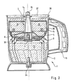
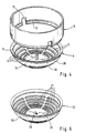
- FIG. 1 to 3 show an advantageous embodiment of a comminution device 1 according to the present invention.
- This is schematic in Fig. 1 as an exploded view shown.
- Figures 2 and 3 show the shredding device 1 in section.
- the same or similar components are provided with the same reference numerals.
- the comminution device 1 has an essentially cylindrical container body 2 on, which has a container bottom 29 at its lower end.
- the container body 2 stands on a container foot 18 which is integrally connected to the container body 2.
- the container foot 18 is designed as a truncated cone, the circumference of which widens towards the bottom.
- a handle 19 integrally connected to the container wall 6. It is the handle 19 is formed as a U-shaped hollow body to save weight.
- the webs 7 are integrally connected to the container wall 6 and run parallel to the central axis 22 of the container body 2.
- the webs 7 do not extend over the entire Height of the container body 2 but end at about 2/3 of the height of the container body Second
- the comminution device 1 has a comminution tool 3, which essentially is formed from a tool spindle 14 and associated blades 8.
- the Tool spindle 14 is a slightly conical hollow rotating part made of metal, which on its bottom wide end is open. At the upper end of the tool spindle 14 there is a toothing 15 available as a clutch for power transmission from a drive unit the shredding device 1 is used. The lower end of the tool spindle 14 is through closed a pin receptacle 23 made of soft metal.
- the tool spindle 14 Furthermore, on the outer circumference of the tool spindle 14 are offset by 90 ° in its lower third four blades 8 attached.
- the blades 8 are also offset in height and angled at different angles so that the of them on the food Exerted force is also directed in the direction of the openings 9, 31, 35 in order to to quickly let the chopped food pass through openings 9, 31, 35, as soon as they have reached the passage width of the openings 9, 31, 35. This will make one too Severe crushing of food and, in the case of ice, thawing too quickly avoided.
- the shredding tool 3 is in the assembled state in the processing area 20, i.e. arranged in the upper half of the container body 2.
- this editing area 20 are the grinding tool 3, a sieve 4, concentric with the center line 22 and a sieve holder 5 are arranged.
- the lower half of the container body 2 serves as a collection area 21 for the food comminuted in the processing area 20.
- the sieve 4 is frustoconical, the side walls 36, which the Crushing tool 3 surrounded, elongated horizontally and parallel to each other Have slots 9.
- the wider upper end of the sieve 4 has an open cross section.
- the sieve 4 closes with a circumferential, as a bead protruding outwardly from the holding edge 17, over the the sieve 4 is connected to a flange 12 at the lower end of the sieve holder 5.
- the screen holder 5 is designed as a circular ring, one on its lower circumference has four recesses 13 arranged offset by 90 °.
- the screen holder also closes 5 on its lower screen holder inner wall 16 with one protruding inwards Bead or flange 12 off.
- the sieve 4 is inserted into the sieve holder 5 from above until the Retaining edge 17 sits on the flange 12. Then the sieve 4 together with the sieve holder 5 inserted into the container body 2, so that the recesses 13 on Sieve holder 5 comprise the upper ends of the webs 7 and are guided by them. The Sieve holder 5 is finally seated on the upper ends of the webs 7. Then the crushing tool 3 installed from above, so that the bearing pin 11, the 10th protrudes vertically, is inserted into the pin holder. Designed as a soft metal bushing Pin receptacle 23 and the bearing pin 11 thereby result in a type of plain bearing for the Tool spindle 14.
- the comminution device 1 is also included a cover, not shown, covered and via the teeth 15 with a drive connected to a food processor.
- the lid closes the opening of the container body and sits on its edge.
- the lid can be part of a Gearbox-provided housing (not shown), as is the case with the Extra shredder for the Braun MultiMix quatro pro M880M is the case, for example in the program overview "quality in good shape", edition presented by the applicant 1999/2000, shown on page 18.
- the tool spindle 14 When the food processor is switched on, the tool spindle 14 and thus begins the crushing tool 3 to rotate about the center line 22. This will make them in the editing area 20 arranged food cut up by the rotating blades 8 and flung around in the machining area. Once the sliced food is one piece size reach that are smaller than the slots 9 provided in the sieve 4, reach the Food parts, as indicated in Fig. 3 by arrows 39, in the collection area 21 of the Container body 2. This moves other arranged in the processing area 20 and Foods that have already been partially broken down are further crushed and then reach the end finally also in the collection area 21. Due to the special design of the blades 8 the food is processed at high speed and with high force 20 hurled around and, once they were the right size, through the openings 9, 31, 35 pressed or flung.
- Fig. 4 shows the screen 4 and the screen holder 5 again as a perspective detail.
- the screen 4 during assembly from above through the cylindrical opening the sieve holder 5 is introduced, since the wider holding edge 17 on the flange 12 can come to rest.
- the slots 9 can be clearly seen, which are in different Distance from the central axis 22 in the circumferential direction.
- From the sieve tray 10 protrudes vertically from the bearing pin 11, which is used to support the shredding tool 3 or the tool spindle 14 is used.
- Recesses 13 can be seen as the support of the screen holder 5 on the inner circumference of the container body 2 attached webs 7 serve.
- Fig. 5 shows a further embodiment, namely a fine screen 25, in which the slot width the slots 31 is smaller than that of the slots 9 shown in the previous figures
- Sieve plate 32 shows a bore 33 in which a corresponding bearing pin for a Tool spindle can be anchored.
- Fig. 6 shows another alternative embodiment of an advantageous sieve, namely a Adjusting sieve 26.
- the adjusting sieve 26 is composed of an inner sieve 27 and one Outer sieve 28 constructed, each similar to sieve 4 or 25 from Figures 4 and 5 are designed.
- the inner sieve 27 and the outer sieve have 28, however, have transverse slots 35 which extend in the radial direction.
- the Inner sieve 27 a vertically protruding in the center of its circular sieve bottom 10 Bearing pin 11 on.
- This bearing pin 11 has a not shown at its lower end Anchoring on a bore 33 in the sieve bottom 32 of the outer sieve 28th is recorded.
- the bearing pin 11 not only forms part of the plain bearing for the tool shank but also forms the axis of rotation for turning the Inner sieve 27 against the outer sieve 28.
- the inner sieve 27 is received by the outer sieve in such a way that it can be twisted.
- the outer screen 28 is in turn received in the screen holder 34, which corresponds to the sieve holder 5 and like this recesses distributed over the circumference 13 has.
- the screen holder 34 has one on its inner lower edge Gutter 12 on.
- the inner sieve 27 can be against in the circumferential direction after assembly rotate the outer sieve 28, as indicated by the arrows in FIG. 6. This will the corresponding transverse slots 35 shifted against each other. That way the slot width varies, i.e. the permeability of the adjusting screen 26 increases accordingly to or from.
- the adjusting screen 26 is shown in a top view in FIG. 7.
- the transverse slots 35 are slightly covered, i.e. the inner sieve 27 is rotated relative to the outer sieve 28 so that these do not lie congruently one above the other.
Landscapes
- Engineering & Computer Science (AREA)
- Mechanical Engineering (AREA)
- Food Science & Technology (AREA)
- Physics & Mathematics (AREA)
- Thermal Sciences (AREA)
- General Engineering & Computer Science (AREA)
- Food-Manufacturing Devices (AREA)
- Crushing And Pulverization Processes (AREA)
- Confectionery (AREA)
- Control And Other Processes For Unpacking Of Materials (AREA)
- Disintegrating Or Milling (AREA)
- General Preparation And Processing Of Foods (AREA)
- Drilling And Exploitation, And Mining Machines And Methods (AREA)
Claims (10)
- Dispositif pour découper en morceaux des denrées alimentaires, notamment des morceaux d'oeufs, dans lequel le dispositif comportant un corps de récipient (2), qui est divisé en une zone supérieure de traitement (20) et une zone inférieure de collecte (21), et dans lequel un outil (3) de division en morceaux, qui découpe en morceaux la denrée alimentaire, est formé dans la zone de traitement (20), et dans lequel l'outil (3) de découpage en morceaux est formé par un couteau rotatif et, au niveau de la jonction entre la zone de traitement (20) et la zone de collecte (21) est disposé au moins partiellement un tamis (4;25;26), qui sépare la zone de traitement (20) de la zone de collecte (21), caractérisé en ce que l'outil (3) de division en morceaux comporte une broche porte-outil (24), qui, au niveau de son extrémité inférieure, est montée de manière à pouvoir tourner sur une tige de support (11) sur le fond du tamis (18;32).
- Dispositif selon la revendication 1, caractérisé en ce que le tamis (4;25;26) est agencé en forme de pot, dont les ouvertures (9;31;35) sont formées dans le fond (10) et/ou dans la paroi latérale (36) du pot.
- Dispositif selon la revendication 2, caractérisé en ce que l'outil (3) de découpage en morceaux est formé à hauteur des ouvertures (9;31;35) formées dans la paroi latérale.
- Dispositif selon la revendication 1, caractérisé en ce que le tamis (26) est agencé de manière à être réglable de telle sorte qu'on peut régler différents coefficients de traversée.
- Dispositif selon la revendication 1, caractérisé en ce qu'il est prévu un dispositif (5;34) de retenue de filtre, qui reçoit dans son extrémité inférieure le filtre (4;25;26).
- Dispositif selon la revendication 5, caractérisé en ce que sur le côté intérieur de la paroi (6) du récipient font saillie des barrettes (7) servant à s'engager dans des évidements (13) formés dans le dispositif (5;34) de retenue du filtre.
- Dispositif selon la revendication 1, caractérisé en ce que l'outil (3) de découpage en morceaux comporte plusieurs, de préférence quatre, lames (8) et que les lames sont conformées de telle sorte que les forces, qui lors du découpage en morceaux, agissent sur les denrées alimentaires, sont dirigées en direction des ouvertures (9;31;35).
- Dispositif selon la revendication 7, caractérisé en ce que les lames (8) sont coudées différemment et sont réparties sur la périphérie de la broche porte-outil (14).
- Dispositif selon la revendication 1, caractérisé en ce que sur l'outil (3) de découpage en morceaux est prévu un accouplement (15), qui peut être relié au dispositif mené d'un robot de cuisine actionné électriquement.
- Dispositif selon la revendication 1, caractérisé en ce que le filtre (4;25;26) est remplaçable.
Priority Applications (1)
| Application Number | Priority Date | Filing Date | Title |
|---|---|---|---|
| EP02010008A EP1232711B1 (fr) | 2000-01-15 | 2000-12-19 | Robot de cuisine pour concasser de la glace |
Applications Claiming Priority (2)
| Application Number | Priority Date | Filing Date | Title |
|---|---|---|---|
| DE10001455 | 2000-01-15 | ||
| DE10001455A DE10001455A1 (de) | 2000-01-15 | 2000-01-15 | Vorrichtung zum Zerkleinern von Lebensmitteln |
Related Child Applications (1)
| Application Number | Title | Priority Date | Filing Date |
|---|---|---|---|
| EP02010008A Division EP1232711B1 (fr) | 2000-01-15 | 2000-12-19 | Robot de cuisine pour concasser de la glace |
Publications (3)
| Publication Number | Publication Date |
|---|---|
| EP1127526A2 EP1127526A2 (fr) | 2001-08-29 |
| EP1127526A3 EP1127526A3 (fr) | 2001-09-05 |
| EP1127526B1 true EP1127526B1 (fr) | 2002-08-21 |
Family
ID=7627593
Family Applications (2)
| Application Number | Title | Priority Date | Filing Date |
|---|---|---|---|
| EP00127777A Expired - Lifetime EP1127526B1 (fr) | 2000-01-15 | 2000-12-19 | Robot de cuisine pour la préparation alimentaire |
| EP02010008A Expired - Lifetime EP1232711B1 (fr) | 2000-01-15 | 2000-12-19 | Robot de cuisine pour concasser de la glace |
Family Applications After (1)
| Application Number | Title | Priority Date | Filing Date |
|---|---|---|---|
| EP02010008A Expired - Lifetime EP1232711B1 (fr) | 2000-01-15 | 2000-12-19 | Robot de cuisine pour concasser de la glace |
Country Status (7)
| Country | Link |
|---|---|
| US (1) | US6676051B2 (fr) |
| EP (2) | EP1127526B1 (fr) |
| AT (2) | ATE357868T1 (fr) |
| DE (3) | DE10001455A1 (fr) |
| ES (2) | ES2282341T3 (fr) |
| HK (1) | HK1050465A1 (fr) |
| MX (1) | MXPA01000397A (fr) |
Families Citing this family (54)
| Publication number | Priority date | Publication date | Assignee | Title |
|---|---|---|---|---|
| DE10151231C2 (de) | 2001-10-17 | 2003-08-21 | Maweva Holding Ag Ltd Mettlen | Küchenmaschine zum Zubereiten von Lebensmitteln |
| DE10244716A1 (de) | 2002-09-25 | 2004-04-01 | BSH Bosch und Siemens Hausgeräte GmbH | Arbeitswerkzeug für ein Zerkleinerungsgerät und entsprechendes Zerkleinerungsverfahren |
| DE10244603A1 (de) | 2002-09-25 | 2004-04-15 | BSH Bosch und Siemens Hausgeräte GmbH | Arbeitswerkzeug für Küchengeräte |
| DE10244717B4 (de) * | 2002-09-25 | 2014-11-13 | BSH Bosch und Siemens Hausgeräte GmbH | Haushaltsgerät |
| FR2855740B1 (fr) * | 2003-06-06 | 2005-07-08 | Seb Sa | Accessoire de travail rotatif pour appareil electromenager de preparation culinaire. |
| FR2859899B1 (fr) * | 2003-09-23 | 2008-05-09 | Seb Sa | Dispositif de preparation culinaire comportant un outil rotatif tournant dans une enceinte de travail |
| CA2501031A1 (fr) * | 2004-03-19 | 2005-09-19 | Hamilton Beach/Proctor-Silex, Inc. | Robot culinaire avec capacite de conservation d'aliments |
| EP1656867A1 (fr) | 2004-11-10 | 2006-05-17 | Electrodomesticos Taurus S.L. | Accesssoire pour mixeur à main |
| US7681815B2 (en) | 2005-10-19 | 2010-03-23 | Koninklijke Philips Electronics N.V. | Device for chopping food, in particular pieces of ice |
| USD567017S1 (en) | 2006-03-09 | 2008-04-22 | Hamilton Beach Brands, Inc. | Food processor |
| US20080148949A1 (en) * | 2006-12-21 | 2008-06-26 | David Stephen Wolfe | Blending jar apparatus structured according to the geometric relationship known as Phi |
| FR2912891B1 (fr) * | 2007-02-22 | 2012-08-10 | Seb Sa | Filtre pour la production de glace concassee au moyen d'un mixeur plongeant et dispositif pour la prodcution de glace concassee muni d'un tel filtre |
| GB2480992A (en) * | 2007-05-18 | 2011-12-14 | Mcgill Tech Ltd | Chilled ingredient for beverages |
| US7607600B2 (en) * | 2007-09-13 | 2009-10-27 | Martin Salgado | Meat shredder |
| DE102007056711B4 (de) * | 2007-11-26 | 2013-11-14 | BSH Bosch und Siemens Hausgeräte GmbH | Knet- oder Rührwerkzeug und Küchenmaschine |
| US8695490B2 (en) | 2010-04-01 | 2014-04-15 | Columbia Insurance Company | Drive system |
| DE102010017099B4 (de) * | 2010-05-26 | 2017-03-02 | Leifheit Ag | Antriebsvorrichtung für eine Vorrichtung zur Bearbeitung oder Verarbeitung von Lebensmitteln |
| US8550390B2 (en) | 2010-08-31 | 2013-10-08 | Healthy Foods, Llc | Food based homogenizer |
| US9282853B2 (en) | 2010-08-31 | 2016-03-15 | Healthy Foods, Llc | Food homogenizer |
| US9339148B2 (en) | 2010-08-31 | 2016-05-17 | Healthy Foods, Llc | Supply assembly for a food homogenizer |
| US8800905B2 (en) * | 2011-02-08 | 2014-08-12 | Main Power Electrical Factory Ltd. | Mixing vessel |
| FR2977785B1 (fr) * | 2011-07-13 | 2013-07-05 | Seb Sa | Appareil electromenager de preparation culinaire comportant un dispositif presse-puree |
| FR2977784B1 (fr) * | 2011-07-13 | 2013-07-12 | Seb Sa | Grille de dispositif presse-puree et appareil electromenager de preparation culinaire comportant une telle grille |
| AU2013200579B2 (en) * | 2013-02-05 | 2015-02-12 | Brighteye Innovations, LLC | Essence Extractor |
| USD703995S1 (en) * | 2013-03-01 | 2014-05-06 | Hamilton Beach Brands, Inc. | Kitchen appliance base |
| USD729568S1 (en) | 2013-06-28 | 2015-05-19 | Homeland Housewares, Llc | Dessert maker |
| CN103506196B (zh) * | 2013-10-14 | 2016-01-20 | 海城后英生物工程有限公司 | 一种大豆组织蛋白离心式切碎机 |
| US9332881B2 (en) | 2014-01-17 | 2016-05-10 | Capbran Holdings, Llc | Food mixer |
| US10321785B2 (en) * | 2014-08-15 | 2019-06-18 | Vita-Mix Management Corporation | Blending volume reducing device |
| CN107073732B (zh) | 2014-10-27 | 2020-11-06 | 皇家飞利浦有限公司 | 用于切割食物的装置 |
| CN107148233A (zh) * | 2014-11-04 | 2017-09-08 | 皇家飞利浦有限公司 | 切碎配件、切碎单元以及用于切碎的家用电器 |
| US9675212B2 (en) | 2015-02-03 | 2017-06-13 | Sharkninja Operating Llc | Container for food processing system |
| DE102015206934A1 (de) | 2015-04-16 | 2016-10-20 | BSH Hausgeräte GmbH | Vorrichtung zum Zerkleinern von Lebensmitteln |
| DE102015206935A1 (de) | 2015-04-16 | 2016-10-20 | BSH Hausgeräte GmbH | Durchlassverstellvorrichtung mit Axiallager für Vorrichtung zum Zerkleinern von Lebensmitteln und Vorrichtung zum Zerkleinern von Lebensmitteln mit Durchlassverstellvorrichtung |
| US9968223B2 (en) | 2015-06-12 | 2018-05-15 | Sunbeam Products, Inc. | Blending appliance with paddle blade |
| US10302352B2 (en) * | 2015-08-07 | 2019-05-28 | Adrian Van Luven | Fluid conditioning apparatus |
| BR112017024036B1 (pt) * | 2015-09-03 | 2022-05-03 | Koninklijke Philips N.V. | Aparelho processador de alimentos |
| US10470612B2 (en) | 2016-01-27 | 2019-11-12 | Ideya Labs, LLC | Disposable container blending apparatus and methods |
| US10736465B2 (en) | 2016-01-27 | 2020-08-11 | Ideya Labs, LLC | Blending apparatus and methods |
| US20180049592A1 (en) * | 2016-08-18 | 2018-02-22 | Hamilton Beach Brands, Inc. | Kitchen Appliance for Processing Foodstuff |
| US10835925B2 (en) | 2017-03-23 | 2020-11-17 | Verily Life Sciences Llc | Sieving devices for pupae separation |
| US10772309B2 (en) | 2017-03-23 | 2020-09-15 | Verily Life Sciences Llc | Sieving apparatuses for pupae separation |
| EP3420868A1 (fr) * | 2017-06-30 | 2019-01-02 | Koninklijke Philips N.V. | Appareil pour la nourriture utilisant un tamis |
| CN107374411B (zh) * | 2017-08-21 | 2019-06-14 | 乐清市赛而乐电器科技有限公司 | 硬质食物切碎装置 |
| EP3586685A1 (fr) * | 2018-06-25 | 2020-01-01 | Koninklijke Philips N.V. | Centrifugeuse et procédé de pressage |
| CN109046634A (zh) * | 2018-08-01 | 2018-12-21 | 刘伟国 | 一种切碎处理器 |
| DE102019206029B4 (de) * | 2019-04-26 | 2022-02-10 | De'longhi Braun Household Gmbh | Küchengerät und Zubehörelement zum Abdichten einer Schutzhaube eines Küchengeräts |
| CN110523480B (zh) * | 2019-10-09 | 2024-07-12 | 攀钢集团矿业有限公司 | 一种多粒级矿物制备机 |
| WO2021214330A1 (fr) | 2020-04-24 | 2021-10-28 | De'longhi Braun Household Gmbh | Outil de transformation d'aliments |
| CN111545458B (zh) * | 2020-06-18 | 2021-08-31 | 贾瑞霞 | 一种基于机械传动的冶炼浮渣筛分装置 |
| CN112473905A (zh) * | 2020-11-10 | 2021-03-12 | 李河龙 | 一种中药粉碎机 |
| CN112728836B (zh) * | 2021-01-21 | 2024-07-02 | 珠海格力电器股份有限公司 | 排冰结构、制冰装置及其控制方法和冰箱 |
| GB2616015B (en) * | 2022-02-23 | 2024-05-22 | Delonghi Braun Household Gmbh | Food processor accessory |
| EP4611595A1 (fr) * | 2022-11-01 | 2025-09-10 | De'Longhi Braun Household GmbH | Insert et tamis destinés à être utilisés avec un robot de cuisine |
Family Cites Families (16)
| Publication number | Priority date | Publication date | Assignee | Title |
|---|---|---|---|---|
| US2449666A (en) * | 1945-01-11 | 1948-09-21 | Moseley Nicholas | Culinary strainer for pureeing food |
| DE928788C (de) | 1952-09-11 | 1955-06-10 | Bosch Gmbh Robert | Haushaltkuechenmaschine |
| FR1143914A (fr) * | 1956-02-29 | 1957-10-07 | Cie Hobart | Appareil perfectionné mélangeur-broyeur-tamiseur pour soupes, légumes cuits et autres matières |
| DE6921181U (de) * | 1969-05-24 | 1969-12-11 | Albert Hoppe | Eis-zerkleinerer |
| US3761026A (en) * | 1972-03-30 | 1973-09-25 | F Rohmer | Mixing and grinding apparatus |
| FR2387082A1 (fr) * | 1977-04-14 | 1978-11-10 | Colmant Cuvelier | Dispositif de broyage |
| US4487371A (en) * | 1982-05-13 | 1984-12-11 | Day Thomas E | Comminution apparatus |
| US4605173A (en) * | 1984-04-04 | 1986-08-12 | Edmonds Harvey A | Size reduction machine |
| JPS6149275U (fr) * | 1984-09-05 | 1986-04-02 | ||
| US4759507A (en) * | 1985-04-04 | 1988-07-26 | Quadro Engineering Incorporated | Size reduction machine having an external gap adjustment |
| DE3678356D1 (de) | 1985-08-06 | 1991-05-02 | Kao Corp | Fluessige shampoozusammensetzung. |
| DE3538967C1 (de) | 1985-11-02 | 1987-06-25 | Braun Ag | Zusatzgeraet fuer eine elektrische Kuechenmaschine |
| US5360170A (en) * | 1993-08-20 | 1994-11-01 | Mr. Coffee, Inc. | Chopping attachment for hand held blender |
| JP3151703B2 (ja) * | 1995-08-11 | 2001-04-03 | 深江パウテック株式会社 | 粒状体の解砕整粒装置および環状空間型スクリーン |
| US5607062A (en) * | 1995-08-18 | 1997-03-04 | Quadro Engineering Inc. | Screen module for preparing cosmetics nested screens of different mesh sizes |
| DE19737130C2 (de) * | 1997-08-26 | 2002-10-24 | Bsh Bosch Siemens Hausgeraete | Topfförmiges Arbeitsbehältnis für einen Handrührer oder Stabmixer |
-
2000
- 2000-01-15 DE DE10001455A patent/DE10001455A1/de not_active Withdrawn
- 2000-12-19 DE DE50014204T patent/DE50014204D1/de not_active Expired - Lifetime
- 2000-12-19 AT AT02010008T patent/ATE357868T1/de active
- 2000-12-19 AT AT00127777T patent/ATE222473T1/de not_active IP Right Cessation
- 2000-12-19 ES ES02010008T patent/ES2282341T3/es not_active Expired - Lifetime
- 2000-12-19 EP EP00127777A patent/EP1127526B1/fr not_active Expired - Lifetime
- 2000-12-19 ES ES00127777T patent/ES2181623T3/es not_active Expired - Lifetime
- 2000-12-19 DE DE50000393T patent/DE50000393D1/de not_active Expired - Lifetime
- 2000-12-19 EP EP02010008A patent/EP1232711B1/fr not_active Expired - Lifetime
- 2000-12-27 US US09/748,985 patent/US6676051B2/en not_active Expired - Lifetime
-
2001
- 2001-01-11 MX MXPA01000397A patent/MXPA01000397A/es unknown
-
2003
- 2003-02-13 HK HK03101058.4A patent/HK1050465A1/zh unknown
Also Published As
| Publication number | Publication date |
|---|---|
| MXPA01000397A (es) | 2002-08-06 |
| DE10001455A1 (de) | 2001-07-26 |
| EP1127526A2 (fr) | 2001-08-29 |
| EP1232711B1 (fr) | 2007-03-28 |
| ATE222473T1 (de) | 2002-09-15 |
| DE50014204D1 (de) | 2007-05-10 |
| ES2181623T3 (es) | 2003-03-01 |
| DE50000393D1 (de) | 2002-09-26 |
| ATE357868T1 (de) | 2007-04-15 |
| US6676051B2 (en) | 2004-01-13 |
| HK1050465A1 (zh) | 2003-06-27 |
| US20010008258A1 (en) | 2001-07-19 |
| ES2282341T3 (es) | 2007-10-16 |
| EP1127526A3 (fr) | 2001-09-05 |
| EP1232711A1 (fr) | 2002-08-21 |
Similar Documents
| Publication | Publication Date | Title |
|---|---|---|
| EP1232711B1 (fr) | Robot de cuisine pour concasser de la glace | |
| DE2258841C3 (de) | Elektrische schneidemaschine fuer lebensmittel | |
| EP0269793B1 (fr) | Appareil électroménager de traitement des aliments | |
| EP0222121B1 (fr) | Outil pour couper et mélanger pour robot de cuisine électrique | |
| DE3535939A1 (de) | Elektrische kuechenmaschine zum zerkleinern von lebensmitteln | |
| DE3722339A1 (de) | Motorisch angetriebener gartenabfallhaecksler | |
| DE602004004385T2 (de) | Zerkleinerungsvorrichtung zum zerkleinern von gemüse oder anderen lebensmitteln | |
| EP3962328B1 (fr) | Préparateur de boisson centrifuge pour la production de jus ou de lait végétal | |
| EP0598306B1 (fr) | Déchiqueteur en particulier pour déchets ménagers et débris de jardin | |
| EP3081127B1 (fr) | Dispositif de broyage d'aliments | |
| EP0570677A1 (fr) | Outil broyeur-mélangeur d'un robot de cuisine | |
| EP2845529B1 (fr) | Composante d'un appareil de cuisine | |
| DE102014220631B4 (de) | Küchengerät zum Zerkleinern eines Bearbeitungsguts | |
| DE102008028666A1 (de) | Zerkleinerungsvorrichtung für Lebensmittel | |
| EP0695581B1 (fr) | Hachoir à viande | |
| EP0943278B1 (fr) | Appareil de cuisine | |
| DE1030218B (de) | Zerkleinerungsmaschine fuer Fleisch und aehnliche Produkte | |
| DE2841625A1 (de) | Vorrichtung zum zerkleinern von nahrungsmitteln, insbesondere obst und gemuese | |
| DE4110037A1 (de) | Gartenhaecksler mit messergehaeuse und darin umlaufend anzutreibenden flachmessern | |
| EP2608709B1 (fr) | Dispositif à frottement par adhérence et frottement de glissement réduits | |
| WO2005018886A1 (fr) | Coupe-legumes | |
| DE102017223183B4 (de) | Bearbeitungsvorrichtung für die Zerkleinerung von Verarbeitungsgut | |
| DE3404348A1 (de) | Kuechenmaschine mit motorischem antrieb | |
| DE1607558C (fr) | ||
| DE10244716A1 (de) | Arbeitswerkzeug für ein Zerkleinerungsgerät und entsprechendes Zerkleinerungsverfahren |
Legal Events
| Date | Code | Title | Description |
|---|---|---|---|
| PUAI | Public reference made under article 153(3) epc to a published international application that has entered the european phase |
Free format text: ORIGINAL CODE: 0009012 |
|
| PUAL | Search report despatched |
Free format text: ORIGINAL CODE: 0009013 |
|
| AK | Designated contracting states |
Kind code of ref document: A2 Designated state(s): AT BE CH CY DE DK ES FI FR GB GR IE IT LI LU MC NL PT SE TR |
|
| AX | Request for extension of the european patent |
Free format text: AL;LT;LV;MK;RO;SI |
|
| AK | Designated contracting states |
Kind code of ref document: A3 Designated state(s): AT BE CH CY DE DK ES FI FR GB GR IE IT LI LU MC NL PT SE TR |
|
| AX | Request for extension of the european patent |
Free format text: AL;LT;LV;MK;RO;SI |
|
| 17P | Request for examination filed |
Effective date: 20010726 |
|
| GRAG | Despatch of communication of intention to grant |
Free format text: ORIGINAL CODE: EPIDOS AGRA |
|
| 17Q | First examination report despatched |
Effective date: 20011213 |
|
| GRAG | Despatch of communication of intention to grant |
Free format text: ORIGINAL CODE: EPIDOS AGRA |
|
| GRAH | Despatch of communication of intention to grant a patent |
Free format text: ORIGINAL CODE: EPIDOS IGRA |
|
| GRAH | Despatch of communication of intention to grant a patent |
Free format text: ORIGINAL CODE: EPIDOS IGRA |
|
| AKX | Designation fees paid |
Free format text: AT BE CH CY DE DK ES FI FR GB GR IE IT LI LU MC NL PT SE TR |
|
| GRAA | (expected) grant |
Free format text: ORIGINAL CODE: 0009210 |
|
| AK | Designated contracting states |
Kind code of ref document: B1 Designated state(s): AT BE CH CY DE DK ES FI FR GB GR IE IT LI LU MC NL PT SE TR |
|
| PG25 | Lapsed in a contracting state [announced via postgrant information from national office to epo] |
Ref country code: TR Free format text: LAPSE BECAUSE OF FAILURE TO SUBMIT A TRANSLATION OF THE DESCRIPTION OR TO PAY THE FEE WITHIN THE PRESCRIBED TIME-LIMIT Effective date: 20020821 Ref country code: IE Free format text: LAPSE BECAUSE OF FAILURE TO SUBMIT A TRANSLATION OF THE DESCRIPTION OR TO PAY THE FEE WITHIN THE PRESCRIBED TIME-LIMIT Effective date: 20020821 Ref country code: GR Free format text: LAPSE BECAUSE OF FAILURE TO SUBMIT A TRANSLATION OF THE DESCRIPTION OR TO PAY THE FEE WITHIN THE PRESCRIBED TIME-LIMIT Effective date: 20020821 Ref country code: FI Free format text: LAPSE BECAUSE OF FAILURE TO SUBMIT A TRANSLATION OF THE DESCRIPTION OR TO PAY THE FEE WITHIN THE PRESCRIBED TIME-LIMIT Effective date: 20020821 |
|
| REF | Corresponds to: |
Ref document number: 222473 Country of ref document: AT Date of ref document: 20020915 Kind code of ref document: T |
|
| REG | Reference to a national code |
Ref country code: GB Ref legal event code: FG4D Free format text: NOT ENGLISH |
|
| REG | Reference to a national code |
Ref country code: CH Ref legal event code: EP |
|
| GBT | Gb: translation of ep patent filed (gb section 77(6)(a)/1977) |
Effective date: 20020821 |
|
| REF | Corresponds to: |
Ref document number: 50000393 Country of ref document: DE Date of ref document: 20020926 |
|
| REG | Reference to a national code |
Ref country code: IE Ref legal event code: FG4D Free format text: GERMAN |
|
| PG25 | Lapsed in a contracting state [announced via postgrant information from national office to epo] |
Ref country code: SE Free format text: LAPSE BECAUSE OF FAILURE TO SUBMIT A TRANSLATION OF THE DESCRIPTION OR TO PAY THE FEE WITHIN THE PRESCRIBED TIME-LIMIT Effective date: 20021121 Ref country code: DK Free format text: LAPSE BECAUSE OF FAILURE TO SUBMIT A TRANSLATION OF THE DESCRIPTION OR TO PAY THE FEE WITHIN THE PRESCRIBED TIME-LIMIT Effective date: 20021121 |
|
| PG25 | Lapsed in a contracting state [announced via postgrant information from national office to epo] |
Ref country code: PT Free format text: LAPSE BECAUSE OF FAILURE TO SUBMIT A TRANSLATION OF THE DESCRIPTION OR TO PAY THE FEE WITHIN THE PRESCRIBED TIME-LIMIT Effective date: 20021205 |
|
| PG25 | Lapsed in a contracting state [announced via postgrant information from national office to epo] |
Ref country code: LU Free format text: LAPSE BECAUSE OF NON-PAYMENT OF DUE FEES Effective date: 20021219 Ref country code: AT Free format text: LAPSE BECAUSE OF NON-PAYMENT OF DUE FEES Effective date: 20021219 |
|
| PG25 | Lapsed in a contracting state [announced via postgrant information from national office to epo] |
Ref country code: CY Free format text: LAPSE BECAUSE OF FAILURE TO SUBMIT A TRANSLATION OF THE DESCRIPTION OR TO PAY THE FEE WITHIN THE PRESCRIBED TIME-LIMIT Effective date: 20021231 Ref country code: BE Free format text: LAPSE BECAUSE OF NON-PAYMENT OF DUE FEES Effective date: 20021231 |
|
| ET | Fr: translation filed | ||
| REG | Reference to a national code |
Ref country code: ES Ref legal event code: FG2A Ref document number: 2181623 Country of ref document: ES Kind code of ref document: T3 |
|
| REG | Reference to a national code |
Ref country code: IE Ref legal event code: FD4D Ref document number: 1127526E Country of ref document: IE |
|
| PLBE | No opposition filed within time limit |
Free format text: ORIGINAL CODE: 0009261 |
|
| STAA | Information on the status of an ep patent application or granted ep patent |
Free format text: STATUS: NO OPPOSITION FILED WITHIN TIME LIMIT |
|
| BERE | Be: lapsed |
Owner name: *BRAUN G.M.B.H. Effective date: 20021231 |
|
| PG25 | Lapsed in a contracting state [announced via postgrant information from national office to epo] |
Ref country code: MC Free format text: LAPSE BECAUSE OF NON-PAYMENT OF DUE FEES Effective date: 20030701 |
|
| 26N | No opposition filed |
Effective date: 20030522 |
|
| PG25 | Lapsed in a contracting state [announced via postgrant information from national office to epo] |
Ref country code: LI Free format text: LAPSE BECAUSE OF NON-PAYMENT OF DUE FEES Effective date: 20041231 Ref country code: CH Free format text: LAPSE BECAUSE OF NON-PAYMENT OF DUE FEES Effective date: 20041231 |
|
| REG | Reference to a national code |
Ref country code: CH Ref legal event code: PL |
|
| PGFP | Annual fee paid to national office [announced via postgrant information from national office to epo] |
Ref country code: NL Payment date: 20101124 Year of fee payment: 11 |
|
| PGFP | Annual fee paid to national office [announced via postgrant information from national office to epo] |
Ref country code: GB Payment date: 20101123 Year of fee payment: 11 |
|
| REG | Reference to a national code |
Ref country code: NL Ref legal event code: V1 Effective date: 20120701 |
|
| GBPC | Gb: european patent ceased through non-payment of renewal fee |
Effective date: 20111219 |
|
| PG25 | Lapsed in a contracting state [announced via postgrant information from national office to epo] |
Ref country code: GB Free format text: LAPSE BECAUSE OF NON-PAYMENT OF DUE FEES Effective date: 20111219 |
|
| PG25 | Lapsed in a contracting state [announced via postgrant information from national office to epo] |
Ref country code: NL Free format text: LAPSE BECAUSE OF NON-PAYMENT OF DUE FEES Effective date: 20120701 |
|
| REG | Reference to a national code |
Ref country code: DE Ref legal event code: R081 Ref document number: 50000393 Country of ref document: DE Owner name: DE'LONGHI BRAUN HOUSEHOLD GMBH, DE Free format text: FORMER OWNER: BRAUN GMBH, 61476 KRONBERG, DE Effective date: 20140701 |
|
| REG | Reference to a national code |
Ref country code: FR Ref legal event code: TP Owner name: DE'LONGHI BRAUN HOUSEHOLD GMBH, DE Effective date: 20140922 |
|
| REG | Reference to a national code |
Ref country code: ES Ref legal event code: PC2A Owner name: DE LONGHI BRAUN HOUSEHOLD GMBH Effective date: 20150921 |
|
| REG | Reference to a national code |
Ref country code: FR Ref legal event code: PLFP Year of fee payment: 16 |
|
| REG | Reference to a national code |
Ref country code: FR Ref legal event code: PLFP Year of fee payment: 17 |
|
| REG | Reference to a national code |
Ref country code: FR Ref legal event code: PLFP Year of fee payment: 18 |
|
| PGFP | Annual fee paid to national office [announced via postgrant information from national office to epo] |
Ref country code: DE Payment date: 20191119 Year of fee payment: 20 |
|
| PGFP | Annual fee paid to national office [announced via postgrant information from national office to epo] |
Ref country code: FR Payment date: 20191120 Year of fee payment: 20 Ref country code: IT Payment date: 20191121 Year of fee payment: 20 |
|
| PGFP | Annual fee paid to national office [announced via postgrant information from national office to epo] |
Ref country code: ES Payment date: 20200102 Year of fee payment: 20 |
|
| REG | Reference to a national code |
Ref country code: DE Ref legal event code: R071 Ref document number: 50000393 Country of ref document: DE |
|
| REG | Reference to a national code |
Ref country code: ES Ref legal event code: FD2A Effective date: 20211207 |
|
| PG25 | Lapsed in a contracting state [announced via postgrant information from national office to epo] |
Ref country code: ES Free format text: LAPSE BECAUSE OF EXPIRATION OF PROTECTION Effective date: 20201220 |