EP1127527A2 - Ferrure pour écran de douche avec joint d'étanchéité integré - Google Patents
Ferrure pour écran de douche avec joint d'étanchéité integré Download PDFInfo
- Publication number
- EP1127527A2 EP1127527A2 EP01104243A EP01104243A EP1127527A2 EP 1127527 A2 EP1127527 A2 EP 1127527A2 EP 01104243 A EP01104243 A EP 01104243A EP 01104243 A EP01104243 A EP 01104243A EP 1127527 A2 EP1127527 A2 EP 1127527A2
- Authority
- EP
- European Patent Office
- Prior art keywords
- fitting
- seal
- fitting according
- holding element
- shaped
- Prior art date
- Legal status (The legal status is an assumption and is not a legal conclusion. Google has not performed a legal analysis and makes no representation as to the accuracy of the status listed.)
- Withdrawn
Links
Images


Classifications
-
- E—FIXED CONSTRUCTIONS
- E05—LOCKS; KEYS; WINDOW OR DOOR FITTINGS; SAFES
- E05D—HINGES OR SUSPENSION DEVICES FOR DOORS, WINDOWS OR WINGS
- E05D11/00—Additional features or accessories of hinges
-
- A—HUMAN NECESSITIES
- A47—FURNITURE; DOMESTIC ARTICLES OR APPLIANCES; COFFEE MILLS; SPICE MILLS; SUCTION CLEANERS IN GENERAL
- A47K—SANITARY EQUIPMENT; ACCESSORIES THEREFOR, e.g. TOILET ACCESSORIES
- A47K3/00—Baths; Showers; Appurtenances therefor
- A47K3/28—Showers or bathing douches
- A47K3/30—Screens or collapsible cabinets for showers or baths
- A47K3/36—Articulated screens
-
- E—FIXED CONSTRUCTIONS
- E05—LOCKS; KEYS; WINDOW OR DOOR FITTINGS; SAFES
- E05D—HINGES OR SUSPENSION DEVICES FOR DOORS, WINDOWS OR WINGS
- E05D5/00—Construction of single parts, e.g. the parts for attachment
- E05D5/02—Parts for attachment, e.g. flaps
- E05D5/0246—Parts for attachment, e.g. flaps for attachment to glass panels
-
- E—FIXED CONSTRUCTIONS
- E05—LOCKS; KEYS; WINDOW OR DOOR FITTINGS; SAFES
- E05D—HINGES OR SUSPENSION DEVICES FOR DOORS, WINDOWS OR WINGS
- E05D7/00—Hinges or pivots of special construction
- E05D7/04—Hinges adjustable relative to the wing or the frame
- E05D7/0415—Hinges adjustable relative to the wing or the frame with adjusting drive means
-
- A—HUMAN NECESSITIES
- A47—FURNITURE; DOMESTIC ARTICLES OR APPLIANCES; COFFEE MILLS; SPICE MILLS; SUCTION CLEANERS IN GENERAL
- A47K—SANITARY EQUIPMENT; ACCESSORIES THEREFOR, e.g. TOILET ACCESSORIES
- A47K3/00—Baths; Showers; Appurtenances therefor
- A47K3/28—Showers or bathing douches
- A47K3/30—Screens or collapsible cabinets for showers or baths
- A47K2003/307—Adjustable connections to the wall
-
- E—FIXED CONSTRUCTIONS
- E05—LOCKS; KEYS; WINDOW OR DOOR FITTINGS; SAFES
- E05D—HINGES OR SUSPENSION DEVICES FOR DOORS, WINDOWS OR WINGS
- E05D5/00—Construction of single parts, e.g. the parts for attachment
- E05D5/02—Parts for attachment, e.g. flaps
- E05D5/0246—Parts for attachment, e.g. flaps for attachment to glass panels
- E05D2005/0253—Parts for attachment, e.g. flaps for attachment to glass panels the panels having conical or stepped recesses
-
- E—FIXED CONSTRUCTIONS
- E05—LOCKS; KEYS; WINDOW OR DOOR FITTINGS; SAFES
- E05D—HINGES OR SUSPENSION DEVICES FOR DOORS, WINDOWS OR WINGS
- E05D5/00—Construction of single parts, e.g. the parts for attachment
- E05D5/02—Parts for attachment, e.g. flaps
- E05D5/0246—Parts for attachment, e.g. flaps for attachment to glass panels
- E05D2005/0261—Parts for attachment, e.g. flaps for attachment to glass panels connecting two or more glass panels
- E05D2005/0269—Parts for attachment, e.g. flaps for attachment to glass panels connecting two or more glass panels the panels being coplanar
-
- E—FIXED CONSTRUCTIONS
- E05—LOCKS; KEYS; WINDOW OR DOOR FITTINGS; SAFES
- E05Y—INDEXING SCHEME ASSOCIATED WITH SUBCLASSES E05D AND E05F, RELATING TO CONSTRUCTION ELEMENTS, ELECTRIC CONTROL, POWER SUPPLY, POWER SIGNAL OR TRANSMISSION, USER INTERFACES, MOUNTING OR COUPLING, DETAILS, ACCESSORIES, AUXILIARY OPERATIONS NOT OTHERWISE PROVIDED FOR, APPLICATION THEREOF
- E05Y2800/00—Details, accessories and auxiliary operations not otherwise provided for
- E05Y2800/15—Applicability
- E05Y2800/16—Applicable on combinations of fixed and movable wings
- E05Y2800/162—Applicable on combinations of fixed and movable wings the wings being coplanar when the movable wing is in the closed position
-
- E—FIXED CONSTRUCTIONS
- E05—LOCKS; KEYS; WINDOW OR DOOR FITTINGS; SAFES
- E05Y—INDEXING SCHEME ASSOCIATED WITH SUBCLASSES E05D AND E05F, RELATING TO CONSTRUCTION ELEMENTS, ELECTRIC CONTROL, POWER SUPPLY, POWER SIGNAL OR TRANSMISSION, USER INTERFACES, MOUNTING OR COUPLING, DETAILS, ACCESSORIES, AUXILIARY OPERATIONS NOT OTHERWISE PROVIDED FOR, APPLICATION THEREOF
- E05Y2900/00—Application of doors, windows, wings or fittings thereof
- E05Y2900/10—Application of doors, windows, wings or fittings thereof for buildings or parts thereof
- E05Y2900/114—Application of doors, windows, wings or fittings thereof for buildings or parts thereof for showers
Definitions
- the invention relates to a fitting for a shower partition that Glass panes with at least one fixed side part and sliding or rotating doors.
- the glass panes one below the other and for connection to a wall flush in the Adjustable holding elements on hinges embedded in glass panes or angles or the like non-positively and positively connected.
- the glass panes are adjustable in the holding piece Through hole lying to the center of the holding element eccentrically arranged and penetrated by a connecting screw becomes.
- the insert is on both sides on the outside of the holding element a tool for rotating the holding element and thus for adjustment available.
- one seal is in the other Fitting parts available on the glass side.
- EP 0 841 032 A2 discloses a device for holding and Fastening glass panes to shower cubicles or doors Use finds. It is used to adjust the plates or glass panes to be fastened a twistable to the angle or hinge used Adjustment element proposed.
- the adjustment element has an eccentric Part related to the axis of the fastener that it by twisting allows between the glass pane and the wall make an adjustment.
- a holding part is used, which has a bore and has an annular shoulder formed against which a tension screw puts on.
- a turntable sits in one cylindrical arrangement and has lateral stops in the form of projections on. The stops on the outside are in the area the projections are threaded to apply a cap.
- Such fittings serve, for example, as abutments or are integral Components of a hinge, joint or the like or door plates from Lever sets or rosettes.
- the fitting is on its contact surface, for example a glass wall, a shower cubicle, a door on which the fitting is in place, provide a seal on the side facing it.
- the seal serves to ensure that there is no moisture between Fitting and contact surface accumulates, because this is not one is aesthetic and on the other hand to limescale, mold and the like. ⁇ . leads.
- a seal of the aforementioned type is, for example, DE 43 22 567 C1 can be seen.
- the invention has for its object a fitting or a fastening device to further develop according to the specified type, that with a simple construction while avoiding the disadvantages mentioned a high seal quality is achieved and at the same time a simple one Adjustable fittings and good cleaning of the outside surfaces the glass panes is given.
- the invention is based on the finding that by connecting the seal with the fitting in the plastic state varied Shaping possibilities arise and the tolerances are minimized can. For example, the tolerances of the mounting (fitting) simply by adding additional sealing material be compensated for, and the expensive assembly costs are also eliminated.
- the seal is therefore in the plastic state the fitting connected and shaped.
- the seal is preferably made of a plastic, in particular an elastomer, because this is easily by pressure and Heat can be converted into a plastic state and with different Fitting materials can be connected.
- the seal is in the fitting anchored and in particular has undercuts for this. This improves the quality of the connection between the seal and the fitting increased so that it remains securely in the fitting even when subjected to mechanical influences is anchored. This is particularly important in order to assemble to prevent the seal from detaching from the fitting.
- a groove especially a dovetail-shaped groove, is preferably provided, in which the seal engages.
- Such shapes were previously only possible if the even seal shape is above the The course of the seal was not too great.
- this version can also be used in plastic form a high seal quality can be achieved.
- the seal grips the outer edge of the fitting with an outer part.
- the outer part can also be in a Engage the recess on the edge of the fitting. For aesthetic reasons closes in particular the outer part with the adjoining outer surface of the fitting.
- the seal is in cross section wholly or partially U-shaped, L-shaped, T-shaped and / or + / - shaped educated.
- the shape of the seal is individually dependent the surface, the shape of the fitting and the area of application selected.
- the seal is through Injection molding or transfer molding connected to the fitting and in Formed.
- the seal can also be made using a foaming process connected to the fitting and brought into shape, depending on the requirement and scope of the fitting and the seal.
- the fitting is light and easy to manufacture is made of plastic, especially polyamide.
- the fitting and the seal can now be produced in one process without the fitting being fed into the machine tool must become. For example, in the injection molding machine First the fitting was manufactured, then the tool was changed and immediately afterwards the seal made of an elastic material in the fitting brought in. Basically, it is also possible to use the fitting or to manufacture the fitting part from any material.
- Holding elements are thus inserted into the holes in the glass panes, which have a hole with respect to their center, which is eccentric is arranged to the center.
- the bore preferably has a countersink to a connecting screw or a To be able to accommodate the connecting element. Following the cut there is no through hole for the connecting screw Thread available.
- the holding element is inserted within the hole in the glass pane and then through the eccentric hole inside the holding element the connecting screw passed through.
- the connecting screw can be on the other side of the glass with a Fitting part in the form of a hinge, bracket or suspension get connected.
- a Fitting part in the form of a hinge, bracket or suspension get connected.
- To adjust the glass pane against one fixed wall or another glass pane in the form of a fixed Side part can be on the surface of the holding element existing adjustment options, for example in the form of two spaced apart Hole or a recessed hexagon one Rotation of the holding element about its center can be effected.
- the fact that the connecting screw is not centric is one stepless adjustment and thus adjustment of the glass pane possible. It it goes without saying that this is also done with fittings of a larger type where, for example, within a hinge flap two or three connecting screws are attached.
- a holding element of the aforementioned Art can therefore be used for any type of hardware.
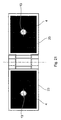
- FIG. 1 shows a fitting 2 which has two hinge tabs 3, which are interconnected by a band eye 17. Within the band tab 3 seals 4 are integrated, which on a contact surface 8 rest against a glass pane 1. The connection between the Glass pane 1 and the band tab 3 by a holding element 20 in connection ensured with a connecting element 21. The holding element 20 is in the glass sheet 1 in a bore, not specified finished flush with an outer surface 19 of the glass sheet.
- FIG. 3 shows a first embodiment of one half of a fitting 2 in the form of a band tab with a seal 4 on a glass pane 1 shown.
- the glass sheet 1 is, for. B. part of a shower door or cabin, via a fastening screw 5, which is in a corresponding thread 7 engages in the fitting 2, is connected to the fitting.
- the Thread 7 is in a thread block, which is fixed in the fitting 2 is introduced.
- the glass pane 1 has a bore 6 for the passage of the screw 5 on.
- a head of the screw 5 ends flush with a bearing attachment.
- the fitting 2 is assigned to a contact surface 8 of the glass pane 1 and has a wall running parallel to the glass pane 1. On the wall is on the glass pane 1 and thus the contact surface 8 facing side in an edge region 15 of the fitting 2 all around the seal 4 introduced.
- the seal 4 closes a gap between the wall of the fitting 2 and the contact surface 8 the glass pane 1 completely.
- the fitting 2 is part of a glass pane 1 with a band connecting a shower cabin construction.
- the glass door formed by the glass pane 1 can be attached to this belt pivoted and thus opened and closed (Figure 18).
- the seal 4 is in cross section rectangular.
- the seal 4 was in the plastic state applied to the wall by injection molding and shaped. she has a firm connection with the fitting 2 and their rectangular Get shape.
- FIG. 4 shows a cross-sectional view of a further fitting 2.
- the fitting 2 is also on the screw 5 as in the first embodiment connected to the glass pane 1, but this is not shown for reasons of clarity.
- the fitting 3 made of plastic, namely polyamide.
- the threaded hole is also introduced.
- the wall has a groove 16 open to the glass pane 1.
- Groove 16 engages the seal 4 and engages around the edge region 15 of the fitting 2. This is shown in FIG. 6 in a partial section. This will clearly that due to the new connection technology seal-fitting completely new types of seals are possible, in particular Undercuts.
- the seal 4 has a slight slope 50, such as this e.g. is indicated in Figure 7.
- the seal 4 consists of a T-shaped area 18 and a Section L-shaped outer region 10.
- the L-shaped outer region 10 is adapted to the outer contour.
- the T-shaped area 18 engages in the Groove 16.
- FIG. 6 An alternative embodiment to FIG. 6 is shown in FIG.
- the Groove 16 is dovetail-shaped and surrounds the seal 4 this time not the edge area 15 of the fitting 2, but is only T-shaped, so it only consists of the T-shaped area 18th
- FIG. 8 A similar seal shape is shown in FIG. 8 in a cross-sectional view as shown in Figures 6 and 7. Closes at the T-shaped area 18 is an L-shaped area 10 to the edge area 15 of the fitting 2 embraces.
- the groove 16 is again dovetail-shaped in section. In order to be able to remove this fitting, the grooves 16 extend to the edges of the fitting.
- FIG. 9 shows a further alternative of a form of a seal 4 and a shape of a groove 16 shown.
- the cross section of the groove 16 is here rectangular and the seal 4 T-shaped, with the edge area 15 of fitting 2 is extended.
- a groove 16 corresponding to FIG. 9 is provided in FIG. 10, however the seal is L-shaped and extends to Edge of the fitting 2 and ends flush with it.
- a modification 10a shows a differently designed edge area, which has a slope 51 which is against the L-shaped area 10 drops.
- the groove 16 is made in two parts.
- a wider groove as well form a narrower groove arranged almost in the center of the wider groove together the groove 34.
- the seal 4 is adapted accordingly, wherein a lower T-shaped area engages in the grooves, extending to the edge of the fitting 2 extends laterally adapted to the contour of the fitting 2 and is flush with the fitting 2.
- An upper area is U-shaped in cross-section, so that two are spaced apart arranged sealing surfaces 14 on the contact surface 8 of the glass sheet 1 concern.
- Figure 12 shows a cross-shaped seal.
- the groove 16 is in one narrower lower part 11 and a wider arranged above Area 9 divided.
- the upper groove 9 does not extend to Edge of the fitting 2.
- the groove 16 is so deep that only an upper region 18 of the seal 4 from the fitting 2 or the groove 16 protrudes.
- FIG 13 the execution of a seal 4 is shown, the one has a rectangular cross section with an upper region 52.
- the lower Part of the seal 4 is in a groove 55, which is located in the edge region 15 of fitting 2 is embedded.
- FIG. 14 A further modification of the seal 4 is shown in FIG. 14, in which the seal 4 has a round contact area 56. This execution the seal 4 is also anchored in a groove 55.
- the band shown in FIG. 15 has a short band flap the right side of the hinge eye 17 and a long hinge tab 3 the left side of the hinge eye 17.
- the tape shown in Figure 15 folded, so that the tape on can see the glass panes 1 in the front view.
- the band tabs 3 are visible through the glass panes 1 are, as usual, 3 counterparts in the same size of the hinge can be used for fastening.
- holding elements 20 here which are punctiform Realize attachment. This inevitably becomes the 23rd designated fitting top of the hinge tab 3 visible.
- this area of the upper side 23 of the fitting is marked by the fourth designated circumferential seals hermetically sealed. Consequently the area behind the hinge tab 3 is visible, but this does not bother, there are no visual impairments due to the integrated seals can take place. If you used conventional seals, so this would not give a decent picture.
- the hinge 3 of the fitting 25 is also as already described with an all-round integrated seal 4 provided.
- the glass pane 1 is fastened via a holding element 20 in connection with a connecting element 21 within the threaded bore 13 of the band tab 3.
- a side seal that works simultaneously is designed as a tee 28 is located in the area of the glass pane 1 in the fastening tab 26.
- an angle bracket is shown in Figures 19 and 20 reproduced for attachment to, for example, a wall 24.
- the leg 30 points to the wall 24 for contact comes, also a seal 4.
- the glass pane 1 is on the repellent Leg 31 connected to this via the holding element 20.
- the integrated is between glass pane 1 and leg 31 Poetry.
- the end of the glass sheet 1 extends into an incision 32 which for example, according to the idea of the invention also with the could be provided plastic seal 4.
- the Visibility of the upper side 23 of the fitting is visible, however, by the corresponding Seal 4 opposite the glass pane 1 when in use of the holding element 20 is sealed.
- FIG. 21 An embodiment is shown in FIG. 21 based on an opened fitting reproduced, which has a flat seal 4. Within the top fitting 23 is the threaded bore 13 for Attachment of the holding element. This flat seal 4 can be equipped with elevations in the edge area.
- FIGS. 22 to 25 the holding element 20 is shown separately once again described, which used in the aforementioned fittings becomes.
- a holding element 20 is shown in a sectional illustration in FIG.
- the holding element 20 shows a cylindrical extension 37 on, which changes into a tapered course 36.
- a center 38 of the holding element 20 is eccentrically to this a bore 34 available, which is provided with a countersink 35.
- In the top view of the 23 also shows adjustment bores 39 for the attachment of a tool to the holding element 20 around its To rotate center point 38. It becomes clear that by twisting of the holding element 20 around its center 38, the bore 34 a circular course starts. However, since the holding element 20 is not on its center 38 is fixed, but via the bore 35, such as To be described below, the holding element 20 does not turn over its center 38 but around the center of the bore 34.
- FIGS. 24 and 25 Another type of adjustment possibility is shown in FIGS. 24 and 25, in which the holding element 20 has a recess in on its upper side
- the shape of a hexagon socket 33 has a corresponding one Tool with a complementary shape can be used for adjustment can.
- the holding element 20 described above is within a hinge for Applied. It is understood that the application for connection on hinge tabs of a hinge is not final, but it can also be used for mounting brackets, mounting brackets, etc. be given.
- the holding element 2 is used in addition to the adjustment for attachment a glass pane 1.
- Inside the glass pane 1 is the holding element 2 of the type described above.
- Between the hinge tab 3 and the glass pane 1 is the seal 4.
- Das Holding element 20, which is within the unspecified bore is inside the glass pane 1, is by a connecting screw 40 permeated.
- the connecting screw 40 within a threaded bore 13, which is in the hinge tab 3 is screwed in.
- the position of the holding element 20 in Figures 1 and 15 can be referred to as the middle position become.
- Figure 26 gives the most varied adjustment options in relation on the bore 34 within the holding member 20 again. It can by the corresponding rotation within the hinge tab 3 on the one hand an upper position 16 of the glass pane can be effected in In contrast, of course, a lower position 44, also a right one Position 43 and a left position 45. The greater the eccentricity of the Hole 34 to the center 38 of the holding element 20 is the larger is the setting range.
Landscapes
- Engineering & Computer Science (AREA)
- Mechanical Engineering (AREA)
- Health & Medical Sciences (AREA)
- Public Health (AREA)
- Epidemiology (AREA)
- General Health & Medical Sciences (AREA)
- Securing Of Glass Panes Or The Like (AREA)
Applications Claiming Priority (2)
| Application Number | Priority Date | Filing Date | Title |
|---|---|---|---|
| DE10009009 | 2000-02-25 | ||
| DE2000109009 DE10009009C2 (de) | 2000-02-25 | 2000-02-25 | Beschlag für eine Duschabtrennung mit einer integrierten Dichtung |
Publications (2)
| Publication Number | Publication Date |
|---|---|
| EP1127527A2 true EP1127527A2 (fr) | 2001-08-29 |
| EP1127527A3 EP1127527A3 (fr) | 2005-03-16 |
Family
ID=7632472
Family Applications (1)
| Application Number | Title | Priority Date | Filing Date |
|---|---|---|---|
| EP01104243A Withdrawn EP1127527A3 (fr) | 2000-02-25 | 2001-02-22 | Ferrure pour écran de douche avec joint d'étanchéité integré |
Country Status (2)
| Country | Link |
|---|---|
| EP (1) | EP1127527A3 (fr) |
| DE (1) | DE10009009C2 (fr) |
Cited By (5)
| Publication number | Priority date | Publication date | Assignee | Title |
|---|---|---|---|---|
| GB2460436A (en) * | 2008-05-29 | 2009-12-02 | Optima Contracting Ltd | Fittings for panels |
| US20110078960A1 (en) * | 2008-06-11 | 2011-04-07 | Dorma Gmbh + Co. Kg | Partitioning Wall Consisting of Transparent Wall Elements |
| US20170355218A1 (en) * | 2016-06-13 | 2017-12-14 | Pr Germany Gmbh | Glass Element For Shower Cubicle |
| DE202018105805U1 (de) | 2018-10-10 | 2018-11-12 | Aug. Winkhaus Gmbh & Co. Kg | Beschlagteil |
| US11339593B2 (en) * | 2020-01-23 | 2022-05-24 | Sixpence Industries Limited | Butt hinge |
Families Citing this family (2)
| Publication number | Priority date | Publication date | Assignee | Title |
|---|---|---|---|---|
| DE202004012023U1 (de) * | 2004-07-31 | 2005-12-22 | Fischerwerke Artur Fischer Gmbh & Co. Kg | Gelenkband für Glastüren |
| DE102012019778B4 (de) | 2012-10-09 | 2014-10-02 | Combia GmbH | Breitenverstellbare Haltevorrichtung für eine rahmenlose Wannenabtrennung und mit dieser ausgestattete Wannenabtrennung sowie Verwendung eines Verstellelements zur Breitenverstellung einer Wannenabtrennung |
Citations (2)
| Publication number | Priority date | Publication date | Assignee | Title |
|---|---|---|---|---|
| DE4322567C1 (de) | 1993-07-07 | 1994-07-28 | Paul Jean Munch | Trennwand für Dusche mit Schwenktüre und Scharnieren |
| EP0841032A2 (fr) | 1996-11-12 | 1998-05-13 | Joachim Fischbach | Dispositif pour la fixation réglable des panneaux, en particulier panneaux de verre ou similaires |
Family Cites Families (3)
| Publication number | Priority date | Publication date | Assignee | Title |
|---|---|---|---|---|
| DE2851722C2 (de) * | 1978-11-30 | 1982-10-21 | Vereinigte Glaswerke Gmbh, 5100 Aachen | Ganzglastür-Beschlag |
| GB8318589D0 (en) * | 1983-07-08 | 1983-08-10 | Blair George Plc | Welded constructions and components |
| EP1020154A3 (fr) * | 1999-01-18 | 2002-02-13 | DORMA GmbH + Co. KG | Cloison de douche |
-
2000
- 2000-02-25 DE DE2000109009 patent/DE10009009C2/de not_active Expired - Fee Related
-
2001
- 2001-02-22 EP EP01104243A patent/EP1127527A3/fr not_active Withdrawn
Patent Citations (2)
| Publication number | Priority date | Publication date | Assignee | Title |
|---|---|---|---|---|
| DE4322567C1 (de) | 1993-07-07 | 1994-07-28 | Paul Jean Munch | Trennwand für Dusche mit Schwenktüre und Scharnieren |
| EP0841032A2 (fr) | 1996-11-12 | 1998-05-13 | Joachim Fischbach | Dispositif pour la fixation réglable des panneaux, en particulier panneaux de verre ou similaires |
Cited By (6)
| Publication number | Priority date | Publication date | Assignee | Title |
|---|---|---|---|---|
| GB2460436A (en) * | 2008-05-29 | 2009-12-02 | Optima Contracting Ltd | Fittings for panels |
| GB2460436B (en) * | 2008-05-29 | 2011-09-07 | Optima Contracting Ltd | Fittings for panels |
| US20110078960A1 (en) * | 2008-06-11 | 2011-04-07 | Dorma Gmbh + Co. Kg | Partitioning Wall Consisting of Transparent Wall Elements |
| US20170355218A1 (en) * | 2016-06-13 | 2017-12-14 | Pr Germany Gmbh | Glass Element For Shower Cubicle |
| DE202018105805U1 (de) | 2018-10-10 | 2018-11-12 | Aug. Winkhaus Gmbh & Co. Kg | Beschlagteil |
| US11339593B2 (en) * | 2020-01-23 | 2022-05-24 | Sixpence Industries Limited | Butt hinge |
Also Published As
| Publication number | Publication date |
|---|---|
| EP1127527A3 (fr) | 2005-03-16 |
| DE10009009A1 (de) | 2001-09-13 |
| DE10009009C2 (de) | 2003-01-02 |
Similar Documents
| Publication | Publication Date | Title |
|---|---|---|
| DE2723850C2 (de) | Möbelscharnier | |
| EP3346078B1 (fr) | Porte de chambre | |
| CH666514A5 (de) | Rahmen fuer mit einer plattenfoermigen fuellung versehene bauteile. | |
| EP1332264B1 (fr) | Element de vis pour fixer un element de ferrures sur un profile creux pourvu d'une partie profilee saillante | |
| DE202013101629U1 (de) | Halteprofil für ein Rahmenprofil sowie rahmenintegrierte Absturzsicherung | |
| EP0995001B1 (fr) | Agencement d'une ferrure montee sur un cadre | |
| DE102007003518B4 (de) | Schraube, insbesondere zur Durchsteckmontage von Fensterrahmen in der Laibung eines Mauerwerks | |
| EP1127527A2 (fr) | Ferrure pour écran de douche avec joint d'étanchéité integré | |
| DE3104973A1 (de) | "aufschraubband, insbesondere fuer schwere fenster- oder tuerfluegel mit kunststoffprofilen" | |
| EP0539672B1 (fr) | Ferrure pour fixation dans une rainure d'un profilé rétréci des deux côtés | |
| DE102004012890B3 (de) | Scharnier zur drehbaren Halterung einer Tür oder eines Fensters an einem Rahmen | |
| DE19943567C2 (de) | Befestigungsvorrichtung für eine Duschabtrennung | |
| DE4320284C2 (de) | Dichtungsanordnung für den Einsatz bei mechanisch miteinander zu verbindenden Pfosten- und Rahmenelementen | |
| EP2228510A2 (fr) | Armature pour la fixation d'une porte de douche | |
| WO2004085780A1 (fr) | Penture, notamment pour portes de douche et/ou portes en verre | |
| DE10042714A1 (de) | Fassade mit Adapterprofil | |
| EP1441096A1 (fr) | Dispositif de fixation pour une ferrure | |
| DE102011008765A1 (de) | Profilanordnung, Rahmen und Rahmenanordnung | |
| EP1491696B1 (fr) | Système d'assemblage de profilés | |
| DE20100618U1 (de) | Rahmenprofil | |
| DE10035569B4 (de) | Beschlagsteil für ein Fenster, eine Tür oder dergleichen | |
| DE102004052896B3 (de) | Scharnier mit wenigstens zwei Scharnierteilen zur Anordnung in Zusammenwirken mt einem Trag- und Aufnahmeelement | |
| DE10008864C2 (de) | Beschlag mit einer Dichtung | |
| EP1522645B1 (fr) | Dispositif et procédé de connexion pour une connexion à traverses et montants | |
| EP1514000B1 (fr) | Systeme pour assembler deux elements dont un au moins comprend deux cavites |
Legal Events
| Date | Code | Title | Description |
|---|---|---|---|
| PUAI | Public reference made under article 153(3) epc to a published international application that has entered the european phase |
Free format text: ORIGINAL CODE: 0009012 |
|
| AK | Designated contracting states |
Kind code of ref document: A2 Designated state(s): AT BE CH CY DE DK ES FI FR GB GR IE IT LI LU MC NL PT SE TR |
|
| AX | Request for extension of the european patent |
Free format text: AL;LT;LV;MK;RO;SI |
|
| PUAL | Search report despatched |
Free format text: ORIGINAL CODE: 0009013 |
|
| AK | Designated contracting states |
Kind code of ref document: A3 Designated state(s): AT BE CH CY DE DK ES FI FR GB GR IE IT LI LU MC NL PT SE TR |
|
| AX | Request for extension of the european patent |
Extension state: AL LT LV MK RO SI |
|
| RIC1 | Information provided on ipc code assigned before grant |
Ipc: 7E 06B 3/54 B Ipc: 7E 05D 11/00 B Ipc: 7E 05D 7/04 B Ipc: 7E 05D 5/02 B Ipc: 7A 47K 3/36 A |
|
| 17P | Request for examination filed |
Effective date: 20050916 |
|
| AKX | Designation fees paid |
Designated state(s): AT BE CH CY DE DK ES FI FR GB GR IE IT LI LU MC NL PT SE TR |
|
| 17Q | First examination report despatched |
Effective date: 20080624 |
|
| RAP1 | Party data changed (applicant data changed or rights of an application transferred) |
Owner name: MUNCH, PAUL-JEAN |
|
| STAA | Information on the status of an ep patent application or granted ep patent |
Free format text: STATUS: THE APPLICATION IS DEEMED TO BE WITHDRAWN |
|
| 18D | Application deemed to be withdrawn |
Effective date: 20100901 |