EP1127546B1 - Tomographe assisté par ordinateur pour détecter le spectre de transmission d'impulsions dans une zone d'inspection - Google Patents
Tomographe assisté par ordinateur pour détecter le spectre de transmission d'impulsions dans une zone d'inspection Download PDFInfo
- Publication number
- EP1127546B1 EP1127546B1 EP01200652A EP01200652A EP1127546B1 EP 1127546 B1 EP1127546 B1 EP 1127546B1 EP 01200652 A EP01200652 A EP 01200652A EP 01200652 A EP01200652 A EP 01200652A EP 1127546 B1 EP1127546 B1 EP 1127546B1
- Authority
- EP
- European Patent Office
- Prior art keywords
- radiation
- detector
- examination zone
- arrangement
- fan beam
- Prior art date
- Legal status (The legal status is an assumption and is not a legal conclusion. Google has not performed a legal analysis and makes no representation as to the accuracy of the status listed.)
- Expired - Lifetime
Links
- 238000001228 spectrum Methods 0.000 title claims description 8
- 230000005540 biological transmission Effects 0.000 title 1
- 238000007689 inspection Methods 0.000 title 1
- 230000005855 radiation Effects 0.000 claims description 55
- 238000012546 transfer Methods 0.000 claims description 9
- 238000002591 computed tomography Methods 0.000 claims description 7
- 238000012545 processing Methods 0.000 claims description 5
- 241000446313 Lamella Species 0.000 claims description 4
- 238000004590 computer program Methods 0.000 claims 2
- 238000000034 method Methods 0.000 description 14
- 238000005259 measurement Methods 0.000 description 6
- 239000000463 material Substances 0.000 description 4
- RYGMFSIKBFXOCR-UHFFFAOYSA-N Copper Chemical compound [Cu] RYGMFSIKBFXOCR-UHFFFAOYSA-N 0.000 description 1
- 238000002441 X-ray diffraction Methods 0.000 description 1
- 238000012512 characterization method Methods 0.000 description 1
- 229910052802 copper Inorganic materials 0.000 description 1
- 239000010949 copper Substances 0.000 description 1
- 230000001419 dependent effect Effects 0.000 description 1
- 238000013461 design Methods 0.000 description 1
- 230000009977 dual effect Effects 0.000 description 1
- 238000011156 evaluation Methods 0.000 description 1
- 238000001914 filtration Methods 0.000 description 1
- 238000011835 investigation Methods 0.000 description 1
- 239000011159 matrix material Substances 0.000 description 1
- 230000000149 penetrating effect Effects 0.000 description 1
- 238000003325 tomography Methods 0.000 description 1
- 230000007704 transition Effects 0.000 description 1
- 238000000411 transmission spectrum Methods 0.000 description 1
- 230000003313 weakening effect Effects 0.000 description 1
Images
Classifications
-
- A—HUMAN NECESSITIES
- A61—MEDICAL OR VETERINARY SCIENCE; HYGIENE
- A61B—DIAGNOSIS; SURGERY; IDENTIFICATION
- A61B6/00—Apparatus or devices for radiation diagnosis; Apparatus or devices for radiation diagnosis combined with radiation therapy equipment
- A61B6/42—Arrangements for detecting radiation specially adapted for radiation diagnosis
- A61B6/4291—Arrangements for detecting radiation specially adapted for radiation diagnosis the detector being combined with a grid or grating
-
- A—HUMAN NECESSITIES
- A61—MEDICAL OR VETERINARY SCIENCE; HYGIENE
- A61B—DIAGNOSIS; SURGERY; IDENTIFICATION
- A61B6/00—Apparatus or devices for radiation diagnosis; Apparatus or devices for radiation diagnosis combined with radiation therapy equipment
- A61B6/02—Arrangements for diagnosis sequentially in different planes; Stereoscopic radiation diagnosis
- A61B6/03—Computed tomography [CT]
- A61B6/032—Transmission computed tomography [CT]
-
- A—HUMAN NECESSITIES
- A61—MEDICAL OR VETERINARY SCIENCE; HYGIENE
- A61B—DIAGNOSIS; SURGERY; IDENTIFICATION
- A61B6/00—Apparatus or devices for radiation diagnosis; Apparatus or devices for radiation diagnosis combined with radiation therapy equipment
- A61B6/48—Diagnostic techniques
- A61B6/483—Diagnostic techniques involving scattered radiation
Definitions
- the invention relates to a computer tomograph with a scanning unit, which is rotatable relative to an examination area about a rotation axis extending through the examination area and the one radiation source for generating a beam, a diaphragm arrangement located between the radiation source and the examination area for generating a fan beam passing through the examination area from the beam and a two-dimensional, a plurality of detector elements comprising detector array comprising a part of its measuring surface primary radiation from the beam fan and with another part of its measuring surface in the examination area generated scattered radiation.
- a computed tomography method in which the examination area is irradiated along a plurality of parallel beam paths and from a plurality of directions with a pencil beam.
- the detector arrangement beyond the examination area not only records the (weakened) primary beam, but also the elastically scattered X-ray radiation.
- Elastic or coherently scattered X-radiation is known to occur when the X-ray quanta lose no energy in the scattering process, while the form of scatter associated with energy loss is called Compton scattering.
- the elastic scattering dominates at small scattering angles (eg ⁇ 10 °), while the Compton scattering predominates at the larger scattering angles.
- the elastically scattered radiation allows a characterization of the matter in the examination area.
- Those detector elements that are not directly exposed to the primary radiation are struck by scattered radiation along the respective primary beam throughout Object of investigation arises.
- the momentum transfer which is proportional to the product of the energy of the scattered quanta and the sine of half the scattering angle, can be reconstructed using an iterative algebraic reconstruction technique (ART), which is described in detail in D1.
- ART iterative algebraic reconstruction technique
- a momentum transfer spectrum (the momentum transfer spectrum represents the intensity of the scattered radiation as a function of the momentum transfer) is obtained for each voxel in the examination area which is characterized by a primary beam. This spectrum is characteristic for the matter in the relevant voxek and thus conclusions about the material composition.
- a disadvantage of this method already mentioned in D1 is the relatively long measuring time for the acquisition of all measurement data required for the reconstruction.
- this measuring time is determined by a computer tomograph z. B. shorten with a fan beam geometry that the measurement data but then more corrupted by unwanted scattered radiation.
- This disadvantage has the method known from WO 99/45843.
- each detector element can receive scattered radiation from the entire scattered-beam fan, that is, also scattered radiation which is scattered at a relatively large scattering angle-predominantly thus Compton scattered radiation, which makes no statement about the material composition of the examination area.
- no reconstruction method is known which would allow the reconstruction of the scatter density in the examination area under such conditions.
- Claim 2 indicates the preferred arrangement.
- the further embodiment according to claim 3 makes it possible with little additional effort to use a computed tomography on the one hand to determine the momentum transfer spectra of the scattered radiation and on the other hand to determine the attenuation of the X-radiation with even further shortened acquisition time (cone beam CT).
- the further embodiment according to claim 4 describes the necessary transition from a fan beam to a beam cone. Claim 5 explains the processing of the different measurement data obtained in the different operating modes.
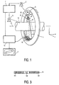
- the computer tomograph shown in FIG. 1 comprises a gantry 1 which can rotate about a rotation axis 14.
- the gantry 1 is driven by a motor 2.
- a radiation source S is fixed, for example an X-ray source.
- the beam used for the examination is determined by a first diaphragm arrangement 31 and / or a second diaphragm arrangement 32.
- the fan beam shown in solid lines results, which is perpendicular to the axis of rotation 14 and in the direction of small dimensions (eg 1mm) has.
- the ray cone 42 indicated by dashed lines results, which has the same shape in a plane perpendicular to the rotation axis 14 as the fan beam 41, but which has substantially larger dimensions in the direction of the rotation axis 14 Has.
- the beam 41 or 42 penetrates through a cylindrical examination region 13, in which e.g. a patient on a patient table (both not shown) or may also be a technical object.
- the radiation beam 41 or 42 strikes a two-dimensional detector arrangement 16 which is attached to the gantry 1 and comprises a plurality of detector elements arranged in the form of a matrix.
- the detector elements are arranged in rows and columns.
- the detector columns are parallel to the axis of rotation, the detector rows may be in planes perpendicular to the axis of rotation, for example on a circular arc around the source S.
- the detector rows typically contain substantially more detector elements (e.g., 1000) than the detector columns (e.g., 16).
- the radiation beams 41 and 42, the examination area 13 and the detector arrangement 16 are adapted to one another.
- the dimensions of this fan beam 41 and of the beam cone 42 are selected such that the examination region 13 is completely transmitted through, and the length of the lines of the detector arrangement is just dimensioned such that the radiation beams 41 and 42, respectively can be fully recorded.
- the beam cone 42 is selected according to the length of the detector columns, so that the beam cone can be completely detected by the detector arrangement 16. If only the fan beam 41 passes through the examination area, it strikes the middle or the detector row (s).
- the object can be rotated in an examination, while the radiation source S and the detector assembly 15 stand still.
- the object can also be displaced parallel to the axis of rotation 14 by means of a motor.
- motors 5 and 2 are running simultaneously, a helical scanning movement of the radiation source S and the detector arrangement 16 results.
- a collimator arrangement 6 which comprises a plurality of plane lamellae 60.
- the lamellae consist of a material strongly absorbing the X-ray radiation and lie in planes which run parallel to the axis of rotation 14 and intersect at the focus of the radiation source S. Their distance from each other can e.g. 1 cm, and each lamella may in the drawing plane have a dimension of e.g. 20 cm.
- the fan beam 41 is subdivided into a number of mutually adjacent sections, so that a column of detector elements can be struck from a section essentially only by primary or stray grinding.
- the measurement data acquired by the detector unit 16 on the rotating gantry 1 are fed to an image processing computer 10, which is usually located at a fixed point in space and connected to the detector unit via a contactless, not shown data slip ring.
- the image processing computer 10 may perform various image processing operations.
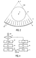
- step 101 a selection of the operating mode takes place in step 101. If the first operating mode (in which the scattered radiation is evaluated) is selected, the process branches to step 102, in which, on the one hand, the first diaphragm arrangement 31 and, on the other hand, the collimator arrangement 6 are moved into the beam path. For the acquisition of the measured values in step 103, therefore, the fan beam 41 is generated.
- the gantry rotates, so that the detector elements detect the primary radiation or the scattered radiation from a multiplicity of angular positions.
- the detector element or elements in the middle of each detector column detect the Primary radiation, while the scattered radiation (secondary radiation) is detected by the further out in a column detector elements.
- FIG. 3 represents a plan view of a column of detector elements.
- the detector elements 161 which detect the scattered radiation are simply hatched, while the detector element 160 (or the detector elements) in the center which detects the primary radiation is marked by a cross.
- On both sides of this central detector element are due to the finite dimensions of the focus of the radiation source detector elements that are struck by scattered radiation but also by a (reduced) primary radiation. It is expedient not to take into account the signals of these detector elements, which are not hatched or crossed in the drawing, in the evaluation.
- the momentum transfer X whose spectrum is to be reconstructed as a function of location u, v, is known to be proportional to the product of the energy of the scattered x-ray quanta and the sine of half the scattering angle (the scattering angle is the angle the trajectory of the scattered x-ray quantum with the trajectory which would have taken the X-ray quantum without the scattering process).
- the further outer detector elements detect the scattered radiation on average at a larger scattering angle than the further inside.
- the location-dependent pulse transmission spectrum is reconstructed. Since the lamellas break up the fan beam into a number of sections, each of which is at least approximately in the form of a pencil beam, the reconstruction can be analogous to the method described in D1. This completes the process (block 105).
- step 101 the sequence branches to block 112, in which the first diaphragm arrangement 31 is moved out of the beam path, so that only the second diaphragm arrangement 32 is effective, which generates a beam cone 42.
- the collimator 6 is removed from the area between the detector arrangement 16 and the examination area 13.
- the gantry rotates about the axis of rotation, wherein all the detector elements can be hit by primary radiation (block 113).
- the subsequent reconstruction step 114 the attenuation in a slice of the examination area is reconstructed.
- a suitable reconstruction method is described in German patent application 198451334 (PHD 98-123).
Landscapes
- Health & Medical Sciences (AREA)
- Life Sciences & Earth Sciences (AREA)
- Engineering & Computer Science (AREA)
- Medical Informatics (AREA)
- Radiology & Medical Imaging (AREA)
- Molecular Biology (AREA)
- Biophysics (AREA)
- High Energy & Nuclear Physics (AREA)
- Veterinary Medicine (AREA)
- Nuclear Medicine, Radiotherapy & Molecular Imaging (AREA)
- Optics & Photonics (AREA)
- Pathology (AREA)
- Public Health (AREA)
- Biomedical Technology (AREA)
- Heart & Thoracic Surgery (AREA)
- Physics & Mathematics (AREA)
- Surgery (AREA)
- Animal Behavior & Ethology (AREA)
- General Health & Medical Sciences (AREA)
- Pulmonology (AREA)
- Theoretical Computer Science (AREA)
- Toxicology (AREA)
- Apparatus For Radiation Diagnosis (AREA)
- Analysing Materials By The Use Of Radiation (AREA)
- Measurement Of Radiation (AREA)
Claims (5)
- Tomographe informatisé avec une unité de balayage qui peut tourner par rapport à une zone d'examen (13) autour d'un axe de rotation (14) traversant la zone d'examen et qui comprend- une source de rayons (S) pour la production d'un faisceau de rayons,- un dispositif de diaphragme (31, 32) se trouvant entre la source de rayons et la zone d'examen pour la production d'un éventail de rayons (41, 42) traversant la zone d'examen à partir du faisceau de rayons,- un agencement de détecteurs (16) bidimensionnel, comprenant plusieurs éléments détecteurs qui saisit, avec une partie de sa surface de mesure, le rayonnement primaire de l'éventail de rayons et, avec une autre partie de sa surface de mesure, le rayonnement diffusé produit dans la zone d'examen et- un dispositif de collimateur (6) disposé entre la zone d'examen (13) et l'agencement de détecteurs (16) avec plusieurs lamelles qui sont disposées dans des plans qui subdivisent l'éventail de rayons en plusieurs segments de telle sorte que les éléments détecteurs se trouvant dans une colonne parallèle à l'axe de rotation soient essentiellement touchés seulement par le rayonnement primaire ou le rayonnement diffusé d'un seul et même segment,
et avec un calculateur de traitement d'image (10) pour la détermination de spectres de transmission d'impulsion pour différents voxels à partir de la zone d'examen (13). - Tomographe informatisé selon la revendication 1,
caractérisé en ce
que les plans dans lesquels sont situés les lamelles se coupent dans le foyer de la source de rayons. - Tomographe informatisé selon la revendication 1,
caractérisé par
un premier mode de fonctionnement dans lequel une partie des éléments détecteurs saisit le rayonnement diffusé qui est produit dans l'éventail de rayons et par un deuxième mode de fonctionnement dans lequel les éléments détecteurs saisissent le rayonnement primaire qui est produit dans un premier cône de rayons dont les dimensions dans la direction de l'axe de rotation sont plus grandes que celles de l'éventail de rayons. - Tomographe informatisé selon la revendication 3,
caractérisé en ce
qu'un premier dispositif de diaphragme est actif entre la source de rayons et la zone d'examen dans le premier mode de fonctionnement pour la production de l'éventail de rayons et un deuxième dispositif de diaphragme est actif dans le deuxième mode de fonctionnement pour la production du cône de rayons dans le trajet des rayons. - Tomographe informatisé selon la revendication 3,
caractérisé par
un premier programme informatique pour le calcul de la distribution de la densité diffusée dans la partie de la zone d'examen traversée par l'éventail de rayons à partir des signaux de détecteur acquis dans le premier mode de fonctionnement et par un deuxième programme informatique pour le calcul de l'atténuation du rayonnement primaire dans la partie de la zone d'examen traversée par le cône de rayons à partir des signaux de détecteur acquis dans le deuxième mode de fonctionnement.
Applications Claiming Priority (2)
| Application Number | Priority Date | Filing Date | Title |
|---|---|---|---|
| DE10009285 | 2000-02-28 | ||
| DE10009285A DE10009285A1 (de) | 2000-02-28 | 2000-02-28 | Computertomograph zur Ermittlung des Impulsübertrags-Spektrums in einem Untersuchungsbereich |
Publications (3)
| Publication Number | Publication Date |
|---|---|
| EP1127546A2 EP1127546A2 (fr) | 2001-08-29 |
| EP1127546A3 EP1127546A3 (fr) | 2002-10-09 |
| EP1127546B1 true EP1127546B1 (fr) | 2006-03-08 |
Family
ID=7632662
Family Applications (1)
| Application Number | Title | Priority Date | Filing Date |
|---|---|---|---|
| EP01200652A Expired - Lifetime EP1127546B1 (fr) | 2000-02-28 | 2001-02-22 | Tomographe assisté par ordinateur pour détecter le spectre de transmission d'impulsions dans une zone d'inspection |
Country Status (4)
| Country | Link |
|---|---|
| US (1) | US6470067B1 (fr) |
| EP (1) | EP1127546B1 (fr) |
| JP (1) | JP2001269331A (fr) |
| DE (2) | DE10009285A1 (fr) |
Families Citing this family (66)
| Publication number | Priority date | Publication date | Assignee | Title |
|---|---|---|---|---|
| EP1392167B1 (fr) * | 2001-04-03 | 2007-10-03 | Koninklijke Philips Electronics N.V. | Appareil de tomographie assistee par ordinateur |
| DE10127267B4 (de) * | 2001-06-05 | 2008-01-03 | Siemens Ag | Bildgebendes medizinsches Röntgengerät |
| DE10201321B4 (de) * | 2002-01-15 | 2011-02-24 | Siemens Ag | Computertomographie-Gerät und Verfahren mit aktiver Anpassung der Mess-Elektronik |
| US6879657B2 (en) * | 2002-05-10 | 2005-04-12 | Ge Medical Systems Global Technology, Llc | Computed tomography system with integrated scatter detectors |
| DE10228941A1 (de) | 2002-06-28 | 2004-01-15 | Philips Intellectual Property & Standards Gmbh | Computer-Tomographiegerät |
| DE10252662A1 (de) * | 2002-11-11 | 2004-05-27 | Philips Intellectual Property & Standards Gmbh | Computertomographie-Verfahren mit kohärenten Streustrahlen und Computertomograph |
| WO2004066215A1 (fr) * | 2003-01-21 | 2004-08-05 | Philips Intellectual Property & Standards Gmbh | Procede de tomographie assistee par ordinateur a rayons coherents disperses et tomographie assistee par ordinateur |
| US7529341B2 (en) * | 2003-02-24 | 2009-05-05 | Koninklijke Philips Electronics N.V. | Automatic material discrimination by using computer tomography |
| US7065175B2 (en) * | 2003-03-03 | 2006-06-20 | Varian Medical Systems Technologies, Inc. | X-ray diffraction-based scanning system |
| WO2004098649A2 (fr) * | 2003-05-06 | 2004-11-18 | Philips Intellectual Property & Standards Gmbh | Appareil et procede pour examiner un objet au moyen de rayons x a dispersion elastique et d'un produit de contraste |
| US7551709B2 (en) * | 2003-05-28 | 2009-06-23 | Koninklijke Philips Electrions N.V. | Fan-beam coherent-scatter computer tomography |
| GB0312499D0 (en) * | 2003-05-31 | 2003-07-09 | Council Cent Lab Res Councils | Tomographic energy dispersive diffraction imaging system |
| FR2856821B1 (fr) * | 2003-06-27 | 2005-08-05 | Commissariat Energie Atomique | Procede de reconstruction d'une image tomographique par une methode analytique comprenant une modelisation amelioree du mouvement de l'objet. |
| JP3961468B2 (ja) * | 2003-09-19 | 2007-08-22 | ジーイー・メディカル・システムズ・グローバル・テクノロジー・カンパニー・エルエルシー | 放射線計算断層画像装置およびそれに用いる放射線検出器 |
| ATE381746T1 (de) * | 2003-10-14 | 2008-01-15 | Koninkl Philips Electronics Nv | Kohärenzstreuungs-computertomographie |
| JP2007508559A (ja) * | 2003-10-14 | 2007-04-05 | コーニンクレッカ フィリップス エレクトロニクス エヌ ヴィ | 扇ビーム・コヒーレント散乱コンピュータ断層撮影法 |
| US20070127621A1 (en) * | 2003-10-14 | 2007-06-07 | Michael Grass | Asymmetric csct |
| US7693318B1 (en) | 2004-01-12 | 2010-04-06 | Pme Ip Australia Pty Ltd | Method and apparatus for reconstruction of 3D image volumes from projection images |
| CN1910447A (zh) * | 2004-01-16 | 2007-02-07 | 皇家飞利浦电子股份有限公司 | 计算机层析x射线摄影机和用于检测在对象中弹性散射的射线的辐射检测器 |
| EP1727467A1 (fr) * | 2004-03-10 | 2006-12-06 | Philips Intellectual Property & Standards GmbH | Tomographie informatique a diffusion coherente mise au point |
| WO2005102170A1 (fr) * | 2004-04-21 | 2005-11-03 | Philips Intellectual Property & Standards Gmbh | Tomodensitometre a diffusion coherente par faisceau en eventail |
| EP1758503A1 (fr) | 2004-06-07 | 2007-03-07 | Philips Intellectual Property & Standards GmbH | Tomographe assiste par ordinateur a diffusion coherente |
| DE102004035943B4 (de) * | 2004-07-23 | 2007-11-08 | GE Homeland Protection, Inc., , Newark | Röntgencomputertomograph sowie Verfahren zur Untersuchung eines Prüfteils mit einem Röntgencomputertomographen |
| US20090185655A1 (en) * | 2004-10-06 | 2009-07-23 | Koninklijke Philips Electronics N.V. | Computed tomography method |
| GB0423707D0 (en) * | 2004-10-26 | 2004-11-24 | Koninkl Philips Electronics Nv | Computer tomography apparatus and method of examining an object of interest with a computer tomography apparatus |
| US8189002B1 (en) | 2004-10-29 | 2012-05-29 | PME IP Australia Pty, Ltd. | Method and apparatus for visualizing three-dimensional and higher-dimensional image data sets |
| US7778392B1 (en) | 2004-11-02 | 2010-08-17 | Pme Ip Australia Pty Ltd | Method of reconstructing computed tomography (CT) volumes suitable for execution on commodity central processing units (CPUs) and graphics processors, and apparatus operating in accord with those methods (rotational X-ray on GPUs) |
| DE102004060609A1 (de) * | 2004-12-16 | 2006-06-29 | Yxlon International Security Gmbh | Verfahren zum Messen des Impulsübertragungsspektrums von elastisch gestreuten Röntgenquanten |
| US7609884B1 (en) | 2004-12-23 | 2009-10-27 | Pme Ip Australia Pty Ltd | Mutual information based registration of 3D-image volumes on GPU using novel accelerated methods of histogram computation |
| GB0500535D0 (en) | 2005-01-12 | 2005-02-16 | Koninkl Philips Electronics Nv | Computer tomography apparatus |
| US7623732B1 (en) | 2005-04-26 | 2009-11-24 | Mercury Computer Systems, Inc. | Method and apparatus for digital image filtering with discrete filter kernels using graphics hardware |
| DE102005021062A1 (de) * | 2005-05-06 | 2006-11-09 | Siemens Ag | Verfahren zur Streustrahlungskorrektur bei Röntgenuntersuchungen mit einem flächigen elektronischen Vielzeilendetektor und Röntgenanlage zur Durchführung des Verfahrens |
| CN101218501A (zh) * | 2005-07-07 | 2008-07-09 | 皇家飞利浦电子股份有限公司 | 多重散射校正 |
| WO2007046023A2 (fr) * | 2005-10-20 | 2007-04-26 | Philips Intellectual Property & Standards Gmbh | Formes perfectionnees de detecteur de tomographie informatisee par diffusion coherente (csct) |
| US8019151B2 (en) * | 2007-06-11 | 2011-09-13 | Visualization Sciences Group, Inc. | Methods and apparatus for image compression and decompression using graphics processing unit (GPU) |
| US8392529B2 (en) | 2007-08-27 | 2013-03-05 | Pme Ip Australia Pty Ltd | Fast file server methods and systems |
| WO2009067675A1 (fr) | 2007-11-23 | 2009-05-28 | Mercury Computer Systems, Inc. | Système de visualisation client-serveur à traitement de données hybride |
| WO2009067680A1 (fr) | 2007-11-23 | 2009-05-28 | Mercury Computer Systems, Inc. | Procédés et appareil de segmentation automatique d'image |
| US9904969B1 (en) | 2007-11-23 | 2018-02-27 | PME IP Pty Ltd | Multi-user multi-GPU render server apparatus and methods |
| US10311541B2 (en) | 2007-11-23 | 2019-06-04 | PME IP Pty Ltd | Multi-user multi-GPU render server apparatus and methods |
| US8319781B2 (en) | 2007-11-23 | 2012-11-27 | Pme Ip Australia Pty Ltd | Multi-user multi-GPU render server apparatus and methods |
| US8009794B2 (en) * | 2008-01-30 | 2011-08-30 | Varian Medical Systems, Inc. | Methods, apparatus, and computer-program products for increasing accuracy in cone-beam computed tomography |
| US8873703B2 (en) * | 2008-05-08 | 2014-10-28 | Arineta Ltd. | X ray imaging system with scatter radiation correction and method of using same |
| DE102009052627B4 (de) * | 2009-11-10 | 2012-07-12 | Siemens Aktiengesellschaft | Streustrahlungskollimator und Verfahren zur Herstellung eines Streustrahlungskollimators |
| DE102011050051B4 (de) * | 2011-05-02 | 2021-10-21 | Deutsches Zentrum für Luft- und Raumfahrt e.V. | Transmissionsprüfvorrichtung und Transmissionsprüfverfahren zum Prüfen von Werkstücken |
| DE102012008640A1 (de) | 2012-05-02 | 2013-11-07 | Heraeus Noblelight Gmbh | Verfahren zur Herstellung eines optischen Moduls mit einer Polymeroptik |
| US9111379B2 (en) * | 2012-06-28 | 2015-08-18 | Mobius Imaging, Llc | Method and system for X-ray CT imaging |
| US9125613B2 (en) | 2012-06-12 | 2015-09-08 | Mobius Imaging, Llc | Detector system for imaging device |
| DE102012110210B4 (de) | 2012-10-25 | 2017-06-01 | Heraeus Sensor Technology Gmbh | Hochtemperaturchip mit hoher Stabilität |
| CN102914555B (zh) * | 2012-11-19 | 2015-05-20 | 四川大学 | L形结构的单源x射线透射与康普顿散射安检装置 |
| DE102013200337B4 (de) * | 2013-01-11 | 2021-11-11 | Siemens Healthcare Gmbh | Verfahren, Computertomopraph und Computerprogrammprodukt zum Bestimmen von Intensitätswerten einer Röntgenstrahlung zur Dosismodulation |
| US10540803B2 (en) | 2013-03-15 | 2020-01-21 | PME IP Pty Ltd | Method and system for rule-based display of sets of images |
| US10070839B2 (en) | 2013-03-15 | 2018-09-11 | PME IP Pty Ltd | Apparatus and system for rule based visualization of digital breast tomosynthesis and other volumetric images |
| US8976190B1 (en) | 2013-03-15 | 2015-03-10 | Pme Ip Australia Pty Ltd | Method and system for rule based display of sets of images |
| US11244495B2 (en) | 2013-03-15 | 2022-02-08 | PME IP Pty Ltd | Method and system for rule based display of sets of images using image content derived parameters |
| US11183292B2 (en) | 2013-03-15 | 2021-11-23 | PME IP Pty Ltd | Method and system for rule-based anonymized display and data export |
| US9509802B1 (en) | 2013-03-15 | 2016-11-29 | PME IP Pty Ltd | Method and system FPOR transferring data to improve responsiveness when sending large data sets |
| JP6289223B2 (ja) * | 2013-04-04 | 2018-03-07 | キヤノンメディカルシステムズ株式会社 | X線コンピュータ断層撮影装置 |
| CN105612416B (zh) * | 2013-07-25 | 2019-01-01 | 模拟技术公司 | 对象内物品的衍射特征的生成 |
| CN104122277B (zh) * | 2014-07-28 | 2016-08-24 | 重庆大学 | 一种线缆的计算机层析成像检测装置 |
| CN104076047A (zh) * | 2014-07-28 | 2014-10-01 | 重庆大学 | 一种流体渗流过程监测的计算机层析成像系统 |
| US9405990B2 (en) * | 2014-08-19 | 2016-08-02 | Morpho Detection, Llc | X-ray diffraction imaging system with signal aggregation across voxels containing objects and method of operating the same |
| US9984478B2 (en) | 2015-07-28 | 2018-05-29 | PME IP Pty Ltd | Apparatus and method for visualizing digital breast tomosynthesis and other volumetric images |
| US11599672B2 (en) | 2015-07-31 | 2023-03-07 | PME IP Pty Ltd | Method and apparatus for anonymized display and data export |
| US9939393B2 (en) | 2015-09-28 | 2018-04-10 | United Technologies Corporation | Detection of crystallographic properties in aerospace components |
| US10909679B2 (en) | 2017-09-24 | 2021-02-02 | PME IP Pty Ltd | Method and system for rule based display of sets of images using image content derived parameters |
Family Cites Families (8)
| Publication number | Priority date | Publication date | Assignee | Title |
|---|---|---|---|---|
| FR2249517B1 (fr) * | 1973-10-30 | 1976-10-01 | Thomson Csf | |
| US4149247A (en) * | 1975-12-23 | 1979-04-10 | Varian Associates, Inc. | Tomographic apparatus and method for reconstructing planar slices from non-absorbed and non-scattered radiation |
| DE2926456A1 (de) * | 1979-06-30 | 1981-01-15 | Philips Patentverwaltung | Verfahren zur ermittlung des randes eines koerpers mittels am koerper gestreuter strahlung |
| DE3406905A1 (de) * | 1984-02-25 | 1985-09-05 | Philips Patentverwaltung Gmbh, 2000 Hamburg | Roentgengeraet |
| DE3886753D1 (de) * | 1988-10-17 | 1994-02-10 | Siemens Ag | Verfahrenzum Betrieb eines Computertomographen. |
| RU2145485C1 (ru) | 1998-03-12 | 2000-02-20 | Кванта Вижн, Инк. | Ультрамалоугловая рентгеновская томография |
| DE19845133A1 (de) | 1998-10-01 | 2000-04-06 | Philips Corp Intellectual Pty | Computertomographie-Verfahren mit kegelförmigem Strahlenbündel |
| DE19947537A1 (de) * | 1999-10-02 | 2001-04-05 | Philips Corp Intellectual Pty | Gitter zur Absorption von Röntgenstrahlung |
-
2000
- 2000-02-28 DE DE10009285A patent/DE10009285A1/de not_active Withdrawn
-
2001
- 2001-02-22 EP EP01200652A patent/EP1127546B1/fr not_active Expired - Lifetime
- 2001-02-22 DE DE50109149T patent/DE50109149D1/de not_active Expired - Lifetime
- 2001-02-26 JP JP2001050821A patent/JP2001269331A/ja not_active Withdrawn
- 2001-02-28 US US09/795,019 patent/US6470067B1/en not_active Expired - Fee Related
Non-Patent Citations (1)
| Title |
|---|
| GRANT JA, MORGAN MJ, DAVIS JR, WELLS P: "Reconstruction strategy suited to x-ray diffraction tomography", OPTICAL SOCIETY OF AMERICA, ISSN 0740-3232, vol. 12, no. 2, - February 1995 (1995-02-01), USA, pages 291 - 300 * |
Also Published As
| Publication number | Publication date |
|---|---|
| EP1127546A3 (fr) | 2002-10-09 |
| US6470067B1 (en) | 2002-10-22 |
| DE50109149D1 (de) | 2006-05-04 |
| EP1127546A2 (fr) | 2001-08-29 |
| DE10009285A1 (de) | 2001-08-30 |
| JP2001269331A (ja) | 2001-10-02 |
Similar Documents
| Publication | Publication Date | Title |
|---|---|---|
| EP1127546A2 (fr) | Tomographe assisté par ordinateur pour détecter le spectre de transmission d'impulsions dans une zone d'inspection | |
| DE60222768T2 (de) | Computertomograph | |
| EP0989520B1 (fr) | Procédé de tomographie par calculateur avec faisceau en forme conique | |
| DE102006015356B4 (de) | Verfahren zur Erzeugung projektiver und tomographischer Phasenkontrastaufnahmen mit einem Röntgen-System | |
| DE102014202330B3 (de) | Single Source DualEnergy mit zwei Filtern zur Röntgenspektrumsdifferenzierung bei Strahlerblenden mit Schlitzplatte | |
| EP0028431B1 (fr) | Dispositif pour la mesure de la répartition de densité d'un rayonnement dispersé dans une zône plane à examiner | |
| DE10252662A1 (de) | Computertomographie-Verfahren mit kohärenten Streustrahlen und Computertomograph | |
| DE102006017290A1 (de) | Fokus/Detektor-System einer Röntgenapparatur zur Erzeugung von Phasenkontrastaufnahmen | |
| DE19835296A1 (de) | Computertomograph mit kegelförmigen Strahlenbündel und helixförmiger Abtastbahn | |
| DE102013203541A1 (de) | Röntgen-CT-Abtastung und Dual-Source-CT-System | |
| DE102004063711A1 (de) | Mehrdetektor-CT-Bildgebungsverfahren und -vorrichtung mit Streustrahlungsverringerung | |
| DE102005048388B4 (de) | Verfahren zur Strahlungskorrektur eines CT-Systems | |
| DE102015206363B3 (de) | Filteranordnung für CT-System mit mehreren Röntgenquellen | |
| EP1116475B1 (fr) | Procédé de création d'un scanogramme par tomodensiométrie | |
| DE102010042683B4 (de) | Einrichtung und Verfahren zur Erzeugung von Röntgenstrahlung sowie Rechenprogramm und Datenträger | |
| DE102005048891B4 (de) | Verfahren zur Kalibrierung eines CT-Systems mit mindestens zwei winkelversetzt zueinander angeordneten Fokus/Detektorsystemen und Computertomographie-System | |
| EP1177767B1 (fr) | Tomographie par ordinateur à faisceau conique et mouvement relatif hélicoidal | |
| DE102007046281A1 (de) | Verfahren und Recheneinheit zur Messung der Flussgeschwindigkeit eines Kontrastmittels in einem Gefäß eines Patienten | |
| DE2609925A1 (de) | Anordnung zur ermittlung der raeumlichen verteilung der absorption eines koerpers | |
| EP1754969A1 (fr) | Tomodensitomètre et méthode pour examiner des objects de tailles differentes | |
| DE102010062402B4 (de) | Verfahren zum Gewinnen einer 3 D-Rekonstruktion eines Objekts sowie Röntgenbildaufnahmevorrichtung | |
| DE102009004186A1 (de) | Verfahren zum Betrieb einer Röntgenröhre und eines Detektors in einem CT-System | |
| DE3913302A1 (de) | Computertomographiesystem | |
| DE102006007058A1 (de) | CT-System mit mindestens zwei Fokus/Detektor-Systemen | |
| EP1000408B1 (fr) | Procede de tomographie avec balayage helicoidal d'une zone d'examen |
Legal Events
| Date | Code | Title | Description |
|---|---|---|---|
| PUAI | Public reference made under article 153(3) epc to a published international application that has entered the european phase |
Free format text: ORIGINAL CODE: 0009012 |
|
| AK | Designated contracting states |
Kind code of ref document: A2 Designated state(s): AT BE CH CY DE DK ES FI FR GB GR IE IT LI LU MC NL PT SE TR |
|
| AX | Request for extension of the european patent |
Free format text: AL;LT;LV;MK;RO;SI |
|
| PUAL | Search report despatched |
Free format text: ORIGINAL CODE: 0009013 |
|
| RAP1 | Party data changed (applicant data changed or rights of an application transferred) |
Owner name: PHILIPS CORPORATE INTELLECTUAL PROPERTY GMBH Owner name: KONINKLIJKE PHILIPS ELECTRONICS N.V. |
|
| AK | Designated contracting states |
Kind code of ref document: A3 Designated state(s): AT BE CH CY DE DK ES FI FR GB GR IE IT LI LU MC NL PT SE TR |
|
| AX | Request for extension of the european patent |
Free format text: AL;LT;LV;MK;RO;SI |
|
| RAP1 | Party data changed (applicant data changed or rights of an application transferred) |
Owner name: PHILIPS INTELLECTUAL PROPERTY & STANDARDS GMBH Owner name: KONINKLIJKE PHILIPS ELECTRONICS N.V. |
|
| 17P | Request for examination filed |
Effective date: 20030409 |
|
| AKX | Designation fees paid |
Designated state(s): DE FR GB NL |
|
| 17Q | First examination report despatched |
Effective date: 20030610 |
|
| GRAP | Despatch of communication of intention to grant a patent |
Free format text: ORIGINAL CODE: EPIDOSNIGR1 |
|
| GRAS | Grant fee paid |
Free format text: ORIGINAL CODE: EPIDOSNIGR3 |
|
| GRAA | (expected) grant |
Free format text: ORIGINAL CODE: 0009210 |
|
| AK | Designated contracting states |
Kind code of ref document: B1 Designated state(s): DE FR GB NL |
|
| PG25 | Lapsed in a contracting state [announced via postgrant information from national office to epo] |
Ref country code: NL Free format text: LAPSE BECAUSE OF FAILURE TO SUBMIT A TRANSLATION OF THE DESCRIPTION OR TO PAY THE FEE WITHIN THE PRESCRIBED TIME-LIMIT Effective date: 20060308 |
|
| REG | Reference to a national code |
Ref country code: GB Ref legal event code: FG4D Free format text: NOT ENGLISH |
|
| REF | Corresponds to: |
Ref document number: 50109149 Country of ref document: DE Date of ref document: 20060504 Kind code of ref document: P |
|
| GBT | Gb: translation of ep patent filed (gb section 77(6)(a)/1977) |
Effective date: 20060418 |
|
| REG | Reference to a national code |
Ref country code: GB Ref legal event code: 746 Effective date: 20060419 |
|
| NLV1 | Nl: lapsed or annulled due to failure to fulfill the requirements of art. 29p and 29m of the patents act | ||
| ET | Fr: translation filed | ||
| PLBE | No opposition filed within time limit |
Free format text: ORIGINAL CODE: 0009261 |
|
| STAA | Information on the status of an ep patent application or granted ep patent |
Free format text: STATUS: NO OPPOSITION FILED WITHIN TIME LIMIT |
|
| 26N | No opposition filed |
Effective date: 20061211 |
|
| PGFP | Annual fee paid to national office [announced via postgrant information from national office to epo] |
Ref country code: FR Payment date: 20100311 Year of fee payment: 10 |
|
| PGFP | Annual fee paid to national office [announced via postgrant information from national office to epo] |
Ref country code: GB Payment date: 20100226 Year of fee payment: 10 |
|
| PGFP | Annual fee paid to national office [announced via postgrant information from national office to epo] |
Ref country code: DE Payment date: 20100430 Year of fee payment: 10 |
|
| GBPC | Gb: european patent ceased through non-payment of renewal fee |
Effective date: 20110222 |
|
| REG | Reference to a national code |
Ref country code: FR Ref legal event code: ST Effective date: 20111102 |
|
| REG | Reference to a national code |
Ref country code: DE Ref legal event code: R119 Ref document number: 50109149 Country of ref document: DE Effective date: 20110901 |
|
| PG25 | Lapsed in a contracting state [announced via postgrant information from national office to epo] |
Ref country code: FR Free format text: LAPSE BECAUSE OF NON-PAYMENT OF DUE FEES Effective date: 20110228 |
|
| PG25 | Lapsed in a contracting state [announced via postgrant information from national office to epo] |
Ref country code: GB Free format text: LAPSE BECAUSE OF NON-PAYMENT OF DUE FEES Effective date: 20110222 |
|
| PG25 | Lapsed in a contracting state [announced via postgrant information from national office to epo] |
Ref country code: DE Free format text: LAPSE BECAUSE OF NON-PAYMENT OF DUE FEES Effective date: 20110901 |