EP1127547A1 - Einrichtung zur Anzeige von medizinischen Schichtbildern - Google Patents
Einrichtung zur Anzeige von medizinischen Schichtbildern Download PDFInfo
- Publication number
- EP1127547A1 EP1127547A1 EP01400424A EP01400424A EP1127547A1 EP 1127547 A1 EP1127547 A1 EP 1127547A1 EP 01400424 A EP01400424 A EP 01400424A EP 01400424 A EP01400424 A EP 01400424A EP 1127547 A1 EP1127547 A1 EP 1127547A1
- Authority
- EP
- European Patent Office
- Prior art keywords
- display
- series
- image
- images
- tomographic
- Prior art date
- Legal status (The legal status is an assumption and is not a legal conclusion. Google has not performed a legal analysis and makes no representation as to the accuracy of the status listed.)
- Granted
Links
- 230000007246 mechanism Effects 0.000 claims description 35
- 238000000034 method Methods 0.000 claims description 12
- 239000002872 contrast media Substances 0.000 claims description 7
- 238000002591 computed tomography Methods 0.000 description 64
- 230000006870 function Effects 0.000 description 36
- 239000011159 matrix material Substances 0.000 description 13
- 230000001360 synchronised effect Effects 0.000 description 12
- 238000003745 diagnosis Methods 0.000 description 8
- 238000003384 imaging method Methods 0.000 description 6
- 238000005259 measurement Methods 0.000 description 6
- 239000003550 marker Substances 0.000 description 5
- 238000004891 communication Methods 0.000 description 4
- 230000009467 reduction Effects 0.000 description 4
- 230000003068 static effect Effects 0.000 description 3
- 230000008901 benefit Effects 0.000 description 2
- 230000008859 change Effects 0.000 description 2
- 238000012790 confirmation Methods 0.000 description 2
- 238000010586 diagram Methods 0.000 description 2
- 210000001519 tissue Anatomy 0.000 description 2
- 238000012935 Averaging Methods 0.000 description 1
- 206010028980 Neoplasm Diseases 0.000 description 1
- 230000002159 abnormal effect Effects 0.000 description 1
- 230000005856 abnormality Effects 0.000 description 1
- 230000015572 biosynthetic process Effects 0.000 description 1
- 210000000988 bone and bone Anatomy 0.000 description 1
- 238000005516 engineering process Methods 0.000 description 1
- 230000006872 improvement Effects 0.000 description 1
- 238000007689 inspection Methods 0.000 description 1
- 239000004973 liquid crystal related substance Substances 0.000 description 1
- 238000003825 pressing Methods 0.000 description 1
- 238000007639 printing Methods 0.000 description 1
- 230000008569 process Effects 0.000 description 1
- 238000012360 testing method Methods 0.000 description 1
- XLYOFNOQVPJJNP-UHFFFAOYSA-N water Substances O XLYOFNOQVPJJNP-UHFFFAOYSA-N 0.000 description 1
Images





Classifications
-
- A—HUMAN NECESSITIES
- A61—MEDICAL OR VETERINARY SCIENCE; HYGIENE
- A61B—DIAGNOSIS; SURGERY; IDENTIFICATION
- A61B6/00—Apparatus or devices for radiation diagnosis; Apparatus or devices for radiation diagnosis combined with radiation therapy equipment
-
- A—HUMAN NECESSITIES
- A61—MEDICAL OR VETERINARY SCIENCE; HYGIENE
- A61B—DIAGNOSIS; SURGERY; IDENTIFICATION
- A61B6/00—Apparatus or devices for radiation diagnosis; Apparatus or devices for radiation diagnosis combined with radiation therapy equipment
- A61B6/02—Arrangements for diagnosis sequentially in different planes; Stereoscopic radiation diagnosis
- A61B6/03—Computed tomography [CT]
- A61B6/032—Transmission computed tomography [CT]
-
- A—HUMAN NECESSITIES
- A61—MEDICAL OR VETERINARY SCIENCE; HYGIENE
- A61B—DIAGNOSIS; SURGERY; IDENTIFICATION
- A61B6/00—Apparatus or devices for radiation diagnosis; Apparatus or devices for radiation diagnosis combined with radiation therapy equipment
- A61B6/46—Arrangements for interfacing with the operator or the patient
- A61B6/467—Arrangements for interfacing with the operator or the patient characterised by special input means
Definitions
- This invention relates to a display device for displaying a tomographic image used for diagnosis and to a displaying process.
- a film viewer using a backlight called a Schaukasten has been used after printing the image on a film.
- a helical CT device In X-ray CT, a helical CT device has been frequently used, where a patient is helically scanned for collecting data while continuously rotating an X-ray light and moving the patient on a platform in a given rate. More recently, a helical scanning procedure has been using a multi-slice CT device where a plurality of detectors are aligned to simultaneously collect data for multiple slices during one rotation.
- CT image refers to, unless otherwise indicated, a 2D image.
- a device displaying a 2D or 3D image is manufactured and marketed by multiple manufactures. These devices are mainly operated by keyboard input and selection/operation in a display device using a mouse because the system utilizes a fixed hardware (a family such as MAC and DOS/V) for the purpose of universality in a software. To date, a variety of softwares allows us to display a 2D image, 3D image or a plurality of images by dividing a screen.
- An objective of this invention for solving the problems is to provide a display device for a tomographic image which is convenient and of good operability for diplayinn a tomographic image in the manner of paging.
- Another objective of this invention is to provide a display device which can display at least two series of tomographic images in the manner of paging and by which reliable diagnosis can be performed.
- the first aspect of this invention provides a display device for tomographic image, comprising: (a) a display portion for displaying at least one series of tomographic images, (b) a storage mechanism for storing at least one series of tomographic image data, (c) a display-speed setting mechanism for setting a display speed for at least one series of tomographic images, and (d) a controller which receives data from the storage mechanism for the series and displays tomographic images in the manner of paging on the display portion for the series based on a speed set by the display-speed setting mechanism; the display-speed setting mechanism being a mechanical variable knob in a separate case from that comprising the controller.
- the mechanical variable knob is preferably a mechanical slide-bar type variable adjuster.
- the second aspect of this invention provides a display device for tomographic image, comprising: (a) a display portion for displaying at least two series of tomographic images, (b) a storage mechanism for storing at least two series of tomographic image data, (c) a display-speed setting mechanism for setting a display speed of each series for at least two series of tomographic images, and (d) a controller which receives data from the storage mechanism for each series and simultaneously displaying a plurality of series of tomographic images on the display portion for individual series based on a speed set by the display-speed setting mechanism.
- the display device further comprises a synchronization command sending mechanism which matches display speeds for at least two series of tomographic images; whereby, the controller displays tomographic images in the manner of paging while synchronizing display speeds for a plurality series of tomographic images based on a synchronization command from the synchronization command sending mechanism.
- a synchronization command sending mechanism which matches display speeds for at least two series of tomographic images; whereby, the controller displays tomographic images in the manner of paging while synchronizing display speeds for a plurality series of tomographic images based on a synchronization command from the synchronization command sending mechanism.
- the third aspect of this invention uses a mechanical variable adjusting knob as the display-speed setting mechanism in a separate case from that comprising the controller in the above second aspect.
- a mechanical slide-bar type of variable adjuster is particularly preferable.
- the fourth aspect of the this invention provides a recording medium on which a program is recorded for displaying tomographic images on a display by a computer for the practice of the second and third aspects of the present invention.
- This program is adapted to execute the steps comprising: receiving data for at least two series of tomographic images from the storage mechanism, receiving a set of values for display speed for each series of tomographic images, and displaying a plurality series of tomographic images on a display simultaneously by displaying tomographic images in the manner of paging for each series.
- the program is preferably a program for displaying tomographic images by synchronizing a display speed for a plurality series of tomographic images based on a synchronization command which matches a display speed for at least two series of tomographic images.
- Fig.1 schematically shows one series of tomographic images.
- Fig.2 schematically shows two series of tomographic images.
- Fig. 3 is a block diagram illustrating a system configuration of Embodiment 1.
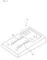
- Fig.4 illustrates an example of an operation unit.
- Fig.5 illustrates an example of an operation panel in an operation unit.
- Fig.6 shows display of two screens for comparison in paging-display.
- Fig.7 schematically shows paging of the left series of images.
- Fig.8 shows an operation panel in Embodiment 2.
- Fig.9 shows display of four screens.
- Fig.10 shows an example of an operation unit.
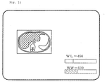
- Fig.11 illustrates a method for indicating CT values according to the prior art.
- Fig.12 illustrates a method for indicating CT values according to this invention.
- Fig.13 illustrates a method for indicating CT values according to this invention.
- a series of tomographic images is a set of multiple tomographic images obtained by taking images under particular conditions for one patient. These include, as illustrated in Fig. 1, n pieces of images from image PN-1 to image PN-n where a given image PN-k and image PN-(k+1) is separated by a predetermined pitch (distance). The pitch is determined by the value calculated by (scan distance) / (image number) if any distance between images is constant.
- a display speed for images is a speed for forward-turning, i.e., forward-paging (or backward-turning, i.e., backward-paging) tomographic images, which may be given in, for example, the number of images turned over in a second.
- Data for a series of tomographic images may comprise data about, for example, a pitch, an image position and imaging conditions .
- the display device for a tomographic image is a device which can display at least one series of tomographic images one by one in the manner of paging and uses a mechanical variable adjusting knob in a separate case (hereinafter, referred to as an "operation panel") from a display (display portion) or a computer. It can set a display speed without using key-input by a keyboard or click or drag using a mouse.
- a mechanical variable adjusting knob allows a user to easily and intuitively change a speed to a proper value in hand while gazing tomographic images displayed in turn on a display without averting his/her eyes.
- variable adjusting knob examples include a mechanical slide-bar type variable adjuster as later described in Examples and a rotating knob.
- the slide-bar type is preferable because an operator can forward-page or backward-page images on the basis of zero point and thus it is quite intuitive.
- the operation panel comprises a start and/or a stop keys .
- a start and a stop keys an operator can move forward (or backward) to a given image and then start forward-turning (or back-turning) using a start key or can stop at an image important for diagnosis to carefully examine the tomographic image.
- the display device for a tomographic image according to the second invention can simultaneously display at least two series of tomographic images on a display (display portion) and can display the tomographic images in the manner of paging at a display speed set for each series.
- Fig.2 schematically shows two series of tomographic images, which are different series mutually related for comparison.
- the tomographic images in the first series are X-ray CT images under normal conditions while the tomographic images in the second series (CN-1 to CN-m) are X-ray contrasted CT image using a contrast medium for the same patient after injecting a contrast medium.
- the images can be displayed in the manner of paging, comparing the simple CTs and the contrasted CTs.
- the first and the second series can be synchronized, i.e., two series of tomographic images can be displayed at the same display speed, to provide different information for the same part in the body, resulting in more exact diagnosis.
- Such a display device for a tomographic image displaying at least two series of tomographic images in the manner of paging on the same display is unknown in the prior art. It is considerably effective because it can conveniently display the same part by synchronizing a plurality of series.
- Different series to be compared with for medical examination may be classified, taking X-ray CT as an example, in terms of (a) use of a contrast medium: simple X-ray CT without a contrast medium and contrasted CT with contrast medium or (b) an imaging time: the latest CT images and previous images (in this case, a plurality series of the data obtained for the different time may be compared.).
- Fig.2 shows the latest imaging series of simple X-ray CTs and a latest imaging series of contrasted CTs, but the latest imaging series of simple X-ray CTs can be compared with a previous imaging series of simple X-ray CTs.
- more than two series may be compared; for example, four series can be compared in a combination of simple CT-latest, contrasted CT-latest, simple CT-previous and contrasted CT-previous, or for images at different times (e.g., simple CTs-latest, previous 1, previous 2 and previous 3).
- an operation program can be executed by controller such that a sub-series image closest to a main-series image is displayed in the light of a pitch or the number of images of the sub-series to the main series or sometimes an image is interpolated.
- tomographic image data stored in a storage mechanism in this invention There are no restrictions to the format of tomographic image data stored in a storage mechanism in this invention.
- the data can be stored for each tomographic image or as data before reconstruction of each tomographic image such as raw data obtained by helical scanning.
- An example of a format for each tomographic image is a data format style in conformity with the DICOM specification which has become a standard format style for a CT image. Any suitable format such as JPEG and BMP (bitmap) may be used.
- JPEG and BMP bitmap
- it is required to store data for mutual relationship between individual image data such as data for the measuring conditions (or storing conditions of the images) including an image pitch and a measurement distance.
- the two or more series of tomographic images when synchronizing and displaying two or more series of tomographic images, can be easily synchronized on the basis of the measurement conditions for each series.
- two or more series of tomographic images can be synchronized while reconstituting tomographic images for a required part in the light of measurement conditions (or storing conditions of the images).
- an operation for setting a display speed and commanding synchronization can be conducted by key-input with a universal keyboard or input by click or drag with a mouse using GUI on a display as interface.
- a display-speed setting mechanism and/or a synchronization command sending mechanism may be a universal keyboard or a mouse cooperatively worked with soft ware which executes such functions.
- Using such a universal keyboard or mouse has an advantage that there are no particular restrictions to the number of series simultaneously displayed, but as described above, there still remains the problem of much stress to an operator in doing key input from a keyboard or in selecting an event by clicking an icon indicated on a screen using a mouse while intensely inspecting images on a screen.
- the third aspect of this invention uses a mechanical variable adjusting knob in a separate case from that accommodating a display (display portion) and a computer body (controller) for setting a display speed in the above second aspect.
- a mechanical variable adjusting knob is described in the first aspect of the present invention.
- the number of mechanical variable adjusting knobs in the operation panel may be appropriately changed in accordance with the purpose of embodiments of the invention.
- the number of variable adjusting knobs are the same as the number of series so as to appropriately change paging speed for each series independently.
- a particular variable adjusting knob such as a variable adjusting knob controlling a main series can control a paging speed in synchronized display.
- a variable adjusting knob exclusively for synchronized display may be provided.
- the number of mechanical variable adjusting knobs may be less than that of series.
- a switching button any kind of switch can be used
- the most preferable style of a mechanical variable adjusting knob is a slide-bar style.
- a key for commanding synchronization and, if a marker function is used, a key for commanding marking are mounted on an operation panel.
- a start and/or a stop keys are mounted on the operation panel.
- the number of the mechanical variable adjusting knobs mounted on the operation panel is usually 1 to 8, preferably 1 to 6, more preferably 1 to 4.
- an image displaying device for a tomographic image according to this invention (the first, the second and the third aspects) further comprises matrix displaying function whereby selected multiple images can be simultaneously displayed on a display.
- the displaying function for example, images for different parts in the same series can be aligned on the same screen.
- the aligned images may be selected with marking function or serial multiple images may be automatically aligned.
- the number of images displayed as a matrix may be changed depending on a size of a display used and a resolution.
- the images are preferably displayed in 2 ⁇ 2 (4 pieces) or 4 ⁇ 4 (16 pieces).
- a switch for switching turning display between matrix display can be mounted together with a mechanical variable adjusting knob in a separate case.
- examples of the storage mechanism include devices integrated in a computer or disposed near a computer such as a hard disk, a flexible disk, a CD-ROM and a RAM.
- the storage mechanism also includes relatively wide category such as a communication system which can receive data from a network. Thus, all data required may not be simultaneously stored in the storage mechanism.
- Fig.3 is a block diagram schematically illustrating a system configuration of the first embodiment of this invention, where a controller portion 1 is equipped with, for example, a CPU 11 and a main memory 12; the CPU executes a program in cooperation with the main memory and controls a storage unit 2, a display unit 4, an input unit 3, an output unit 5 and a network 6, which are all connected to a system bus 7.
- the system bus 7 is a bus for transferring, e.g., image data.
- the storage 2 stores a plurality series of tomographic images and display series selected by the input unit 3 on the display unit 4.
- the network 6 may be the storage mechanism as described above.
- the display unit 4 can display a tomographic image, and may also display, for example, a selection screen for selecting images to be displayed or patient data.
- the device used is preferably an LCD (Liquid Crystal Display) or CRT compliant to a high resolution image.
- the input unit 3 comprises an operation unit 31, a mouse 32 and a keyboard 33.
- operation procedure for inspecting images is exclusively conducted by the operation unit 31, and the mouse and the keyboard may be useful in operation before and/or after additional data input or reading (i.e. inspecting) an image.
- Fig.4 shows an example of the operation unit 31, which is in a separate case from that comprising a controller portion.
- Fig.5 shows an operation panel in the operation unit 31.
- a selection operation unit comprising matrix 4 keys 311 for selecting various items such as a displayed screen and required data including a patient's name, a decision key 312 for deciding selection alternatives, a selection key 313 selecting an item, a call key 314 for displaying a tomographic image constructed on the basis of the recording conditions and a recording key 315 giving a command for recording the present conditions.
- a synchronization key 318 for displaying after synchronizing a display speed for each series for two series to be compared, a start key 319 for starting turning (paging forward or backward) and a stop key 320 for stopping turning (paging forward or backward) of tomographic images.
- the operation unit is connected to the system bus 7 via a wired or infrared communication and the like. An image is displayed in the manner of paging on the basis of a signal from the operation unit.
- the output unit 5 may be a usual printer (monochrome or color). Alternatively, it may have optionally a configuration which can output data to a laser imager for the convenience of the inspection of images using a Schaukasten.
- a screen for selecting a single screen or two screens for comparison is displayed.
- two screens for comparison it is selected using, for example, matrix keys 311 or a decision key 312.
- Matrix keys 311 or a decision key 312 is used for selecting a series displayed in each of the left and the right split screens.
- image series to be displayed in the right and the left screens are selected from the indicated list in the screen.
- vertical and horizontal keys in the matrix 4 keys 311 are used to select an image series displayed in the right screen. After selection, the decision key is pressed for confirmation.
- Vertical and horizontal keys are used to select an image series displayed in the left screen. After selection, the decision key is pressed for confirmation.
- a screen as shown in Fig.6 appears on the display.
- a slide bar for setting an image display speed is operated.
- the slide bar in the operation unit where an image display speed can be changed can be operated to appropriately set a speed for displaying the selected image series.
- the tomographic images in the left screen are turned forward by sliding upward (far side in Fig.4) the slide bar 316 as schematically shown in Fig.7.
- the tomographic images in the left screen are turned backward by sliding downward (near side in Fig.4) the slide bar.
- the slide bar 317 similarly defines paging of the tomographic images in the right screen.
- the numbers by the side of the slide bar indicate a paging speed. In this example, they indicate the number of images per 1 sec. (pieces/sec). Alternatively the unit may be a feeding pitch per 1 sec. (mm/sec). It is not necessary to set the moving distance of the slide bar linearly to the paging speed. In this example, a speed can be finely set within ⁇ 1/4 from the center while images are turned at a 10-fold speed over ⁇ 1/4 from the center. In the latter case, since display is considerably rough, display can be conducted omitting the images at a rate of one per three or two per five.
- the slide bar stays at an appropriate set position and the display screen may be changed in real time depending on moving of the bar.
- the slide bar may be moved continuously or in a multistep style where the bar stays at a particular position with tactile feeling. It is preferable that for zero point, tactile feeling is given for clearly indicating the position.
- a combination of the start key 319 and the stop key 320 can be used to more conveniently conduct the operation of feeding images in a given speed or stopping.
- the start key 319 may be assigned, for example, a function of paging images one by one or restarting after stopping image paging with the stop key.
- the stop key may be pressed to stop the screen at a required image (displaying a given required image) for scrutinizing the tomographic image.
- a synchronization key 318 is operated for displaying the right and the left images in the screen in a synchronized style.
- only the right slide bar 317 is active when operating the key. By operating the slide bar, the right and the left images are simultaneously paged (forward or backward).
- the right and the left images are separately operated to determine a start point.
- the synchronization key is pressed to enter a synchronization state. In this case, if marking function is provided, it is convenient for determining the start point.
- a calling key and a recording key are those related to calling and recording of conditions and environment for display, respectively.
- the conditions can be recorded and next time, the conditions may be called to easily conduct display under the same conditions without again setting conditions.
- a function related to image quality or image expression such as enlargement/reduction or shifting of a screen and CT values.
- a key executing such a function may be mounted in the operation unit or an appropriate combination of selection keys or matrix 4 keys may be used to give a command for such a function.
- a display device for a tomographic image which can simultaneously display four images in the manner of paging.
- the general configuration of the device is as described in Embodiment 2.
- the device of this embodiment comprises an operation unit as shown in Fig.4, on which keys, a track ball and a slide bar as shown in Fig.8 are mounted.
- Fig.9 shows a display where four images are displayed.
- Various combinations of four images are possible; for example, 4 screens/4 series, 4 screens/1 series or 4 screens/2 series.
- Four screens/4 series display is that displays different series allocated to individual split screens; for example, screen A: contrasted CT image (latest), screen B: simple CT image (latest), C: contrasted CT image (previous), screen D: simple CT image (previous); and 4 screens are used for displaying in the manner of paging.
- Four screens/1 series display is that displaying, for example, a series of contrasted CT tomographic images (latest) using four split screens where, for example, screen A may display paging images while screens B, C and D may display static images.
- screen A contrasted CT image (latest) is compared with screen B: simple CT image (latest) and screens C and D are used for displaying these static images.
- screen A: contrasted CT image (latest) and screen B: simple CT image (latest) may be compared while being displayed in the manner of paging and screens C and D may display their enlarged or reduced images in the manner of paging.
- this device comprises screen selection keys 323 and one of three keys may be pressed to select single-screen, two-screen or four-screen display. Here, four-screen display is selected.
- Images displayed in each quadrant screen are selected as described in Embodiment 1, using a track ball 324 and buttons 325 disposed around the ball.
- quadrant screens After selecting, for example, a series to be displayed in each screen, quadrant screens appear on a display as shown in Fig.9. Then, slide bars for setting an image display speed 316a to 316d are operated to appropriately set a speed for displaying an image series.
- the track ball and the buttons may be used to determine which split screen becomes active. It can be set that an image may not be paged even by pressing a start key when the slide bar is at 0 point.
- a synchronization key 318 is used as described in Embodiment 1.
- a starting point of paging may be set using a slide bar allocated to each screen as described in Embodiment 1. Alternatively, it may be set using a track ball.
- the device of this embodiment comprises marker keys 326a to 326d, whereby a starting image may be marked for each series of tomographic images.
- a marker is active (for example, during a marker key is pressed), paging may be always started from an image marked.
- the device of this embodiment comprises an enlargement key 328 and a measurement key 329.
- the enlargement key may be used for enlarging or reducing a selected screen.
- the measurement key 329 is a key for giving a command of measuring CT values (corresponding to brightness) within a selected range.
- a scanning range is defined with the track ball 324 and the button 325 and the measurement key is pressed to display CT values on the display.
- the scanning range may be defined as a circle or as a polygon.
- Fig. 9 shows a range 330 defined as a polygon where an average CT value within the defined range under each image.
- the size of the defined range may be varied; specifically, for a circular range its size may be varied by changing a radius with the button 325 while for a polygonal range its size may be varied by drawing a polygon with the track ball 324 and the button 325.
- an operation unit 31 comprising one mechanical slide bar 316 as illustrated in Fig.10 may be used to realize relatively simple and intuitive operation without complicated functions.
- An image from X-ray CT or MRI is transferred to a controller portion via a network or storage mechanism such as DVD.
- Image data obtained are displayed on a display.
- a single screen or two screens for comparison for example, a simple CT and a contrasted CT is selected.
- Images are displayed in the manner of paging at a given speed.
- a display speed may be determined on the basis of a position of the mechanical slide bar 316 in the operation unit 31 in Fig.10.
- a starting point of paging images is set. This function may be used to mark an image to be examined. Marked images may be displayed in a matrix as described later.
- Images displayed may be fed or back-fed one page in accordance with a trigger command. This function is possible during two-screen display for comparison.
- a given part of an image may be enlarged. Furthermore, enlarged images may be displayed in the manner of paging.
- images marked by the marking function may be displayed as a matrix.
- Operation such as start or stop of paging may be controlled via wired or wireless (e.g., infrared) communication from the operation unit.
- start and stop are controlled with the key 319a in Fig.10.
- a required image is called and displayed on a display.
- a required image is stored in a storage unit in a computer.
- the device of this invention may optionally have function displaying, for example, an image or values required for diagnosis as necessary. Examples of such function may be as follows.
- MPR Multi Planar Reconstruction
- target images are simultaneously aligned. This function may be used in place of a Schaukasten of the prior art.
- Data obtained from multislicing and helical scanning are projected to one direction and data with the highest CT value in each pixel are imaged.
- This function displays an averaged image of scanning data for several pieces. Pictures taken with a fine pitch may provide so enormous amount of scanning data, leading to a longer time for image reading. In this case, information for an abnormal site such as a tumor is certainly included in the image data even after averaging. Therefore, after observing the averaged image, an area around a site where abnormality is suspected may be displayed again in a fine pitch.
- each dot has an inherent CT value (bone: 1000, water: 0, air: -1000) based on a tissue at the site.
- a CT value displayed may be specified with a central CT value (WL) and a CT value width (WW) to display a desired particular tissue.
- Range of CT value for a displayed image may be indicated on a display device by conventionally indicating a central CT value (WL) and a CT value width (WW) with one bar as shown in Fig.11.
- indicating the central CT value (WL) and the CT value width (WW) with one bar is considerably convenient as shown in Fig.12 because one can intuitively understand the displayed range.
- Fig. 13 is an enlarged view of the indicating bar. In this example, the center is indicated with a bold line (or may be highlighted with a different color) and the width is indicated with a given color distinctive from background color.
- a computer as a controller sends a command to locate and reserve area in the form of a bar on the display.
- the bar may be a rectangular shape and each end of the bar defines a minimum value and a maximum value of necessary display range of CT value.
- minimum value and maximum value -1000 and 1000 may used, respectively. Alternatively, these may be set for necessary range for diagnosis.
- the display device may also comprise a receiving portion for receiving a CT value range to be displayed.
- the receiving portion preferably comprises two knobs where one is used for setting the center value and another is used for setting the width, thereby, the range of CT values to be displayed is defined.
- the received CT value range is allocated in the display area in the form of bar.
- the range of CT values is expressed by the distinctive color from that of the display area as CT value width.
- the center of the range is expressed by further visibly distinctive color or shape.
- Such an indication method of CT values is suitably used in a display device for tomographic image of this invention capable of displaying images in the manner of paging, but may be also used in a conventional display device for tomographic image without such a function.
- this invention has been described mainly in relation to an X-ray CT image, but this invention may be used as a display device for a two-dimensional tomographic image such as an MRI image, an angio-image and an angiographic image.
- this invention can provide a display device for a tomographic image which is convenient and of good operability for paging at least two series of tomographic images and thus can provide a display device for a tomographic image allowing us to conduct more reliable diagnosis.
Landscapes
- Health & Medical Sciences (AREA)
- Life Sciences & Earth Sciences (AREA)
- Engineering & Computer Science (AREA)
- Medical Informatics (AREA)
- Radiology & Medical Imaging (AREA)
- Molecular Biology (AREA)
- Biophysics (AREA)
- High Energy & Nuclear Physics (AREA)
- Veterinary Medicine (AREA)
- Nuclear Medicine, Radiotherapy & Molecular Imaging (AREA)
- Optics & Photonics (AREA)
- Pathology (AREA)
- Public Health (AREA)
- Biomedical Technology (AREA)
- Heart & Thoracic Surgery (AREA)
- Physics & Mathematics (AREA)
- Surgery (AREA)
- Animal Behavior & Ethology (AREA)
- General Health & Medical Sciences (AREA)
- Pulmonology (AREA)
- Theoretical Computer Science (AREA)
- Apparatus For Radiation Diagnosis (AREA)
- Processing Or Creating Images (AREA)
- Controls And Circuits For Display Device (AREA)
- User Interface Of Digital Computer (AREA)
Applications Claiming Priority (6)
| Application Number | Priority Date | Filing Date | Title |
|---|---|---|---|
| JP2000044524 | 2000-02-22 | ||
| JP2000044524 | 2000-02-22 | ||
| JP2000285535 | 2000-09-20 | ||
| JP2000285535 | 2000-09-20 | ||
| JP2001038522 | 2001-02-15 | ||
| JP2001038522A JP2002165787A (ja) | 2000-02-22 | 2001-02-15 | 医療用断層画像表示装置 |
Publications (2)
| Publication Number | Publication Date |
|---|---|
| EP1127547A1 true EP1127547A1 (de) | 2001-08-29 |
| EP1127547B1 EP1127547B1 (de) | 2008-06-04 |
Family
ID=27342440
Family Applications (1)
| Application Number | Title | Priority Date | Filing Date |
|---|---|---|---|
| EP01400424A Expired - Lifetime EP1127547B1 (de) | 2000-02-22 | 2001-02-19 | Einrichtung zur Anzeige von medizinischen Schichtbildern |
Country Status (6)
| Country | Link |
|---|---|
| US (1) | US6894707B2 (de) |
| EP (1) | EP1127547B1 (de) |
| JP (1) | JP2002165787A (de) |
| KR (1) | KR100799515B1 (de) |
| CN (1) | CN1259594C (de) |
| DE (1) | DE60134288D1 (de) |
Cited By (4)
| Publication number | Priority date | Publication date | Assignee | Title |
|---|---|---|---|---|
| EP1872721A4 (de) * | 2005-04-07 | 2010-04-28 | Nemoto Kyorindo Co Ltd | Bildanzeigeeinrichtung |
| US9984456B2 (en) | 2004-04-14 | 2018-05-29 | Edda Technology, Inc. | Method and system for labeling hepatic vascular structure in interactive liver disease diagnosis |
| EP1751550B1 (de) * | 2004-04-14 | 2020-05-13 | Edda Technology, Inc. | System, verfahren und graphische benutzeroberfläche zur diagnose von leberkrankheiten |
| US11194461B2 (en) * | 2019-01-15 | 2021-12-07 | Fujifilm Medical Systems U.S.A., Inc. | Smooth image scrolling with dynamic scroll extension |
Families Citing this family (42)
| Publication number | Priority date | Publication date | Assignee | Title |
|---|---|---|---|---|
| JP4331444B2 (ja) * | 2002-07-22 | 2009-09-16 | 株式会社日立メディコ | 医用画像診断装置の撮影条件設定装置 |
| CN100401979C (zh) * | 2002-07-29 | 2008-07-16 | 韦克森林大学 | 采用室壁运动和灌注心脏mri成像的心脏诊断以及心脏诊断系统 |
| CA2494753A1 (en) | 2002-07-29 | 2004-02-05 | Wake Forest University | Cardiac diagnostics using wall motion and perfusion cardiac mri imaging and systems for cardiac diagnostics |
| US7054406B2 (en) * | 2002-09-05 | 2006-05-30 | Kabushiki Kaisha Toshiba | X-ray CT apparatus and method of measuring CT values |
| JP4493323B2 (ja) * | 2003-11-28 | 2010-06-30 | 株式会社日立メディコ | 医用画像表示装置 |
| DE102004008979B4 (de) * | 2004-02-24 | 2006-12-28 | Siemens Ag | Verfahren zur Filterung tomographischer 3D-Darstellungen nach erfolgter Rekonstruktion von Volumendaten |
| CN100508893C (zh) * | 2004-07-21 | 2009-07-08 | 株式会社日立医药 | 断层像摄影装置 |
| US7885440B2 (en) | 2004-11-04 | 2011-02-08 | Dr Systems, Inc. | Systems and methods for interleaving series of medical images |
| US7920152B2 (en) | 2004-11-04 | 2011-04-05 | Dr Systems, Inc. | Systems and methods for viewing medical 3D imaging volumes |
| US7787672B2 (en) | 2004-11-04 | 2010-08-31 | Dr Systems, Inc. | Systems and methods for matching, naming, and displaying medical images |
| US7970625B2 (en) | 2004-11-04 | 2011-06-28 | Dr Systems, Inc. | Systems and methods for retrieval of medical data |
| US7660488B2 (en) | 2004-11-04 | 2010-02-09 | Dr Systems, Inc. | Systems and methods for viewing medical images |
| US20060119622A1 (en) * | 2004-11-23 | 2006-06-08 | General Electric Company | Method and apparatus for volume rendering display protocol |
| JP4170305B2 (ja) * | 2005-04-05 | 2008-10-22 | ジーイー・メディカル・システムズ・グローバル・テクノロジー・カンパニー・エルエルシー | 放射線撮影装置 |
| WO2006109691A1 (ja) * | 2005-04-07 | 2006-10-19 | Nemoto Kyorindo Co., Ltd. | 多段検出装置 |
| JP4624234B2 (ja) * | 2005-10-19 | 2011-02-02 | 富士フイルム株式会社 | 画像再生装置及び画像再生プログラム |
| JP2007215646A (ja) * | 2006-02-15 | 2007-08-30 | Pentax Corp | 内視鏡プロセッサ、静止画像選択プログラム、及び内視鏡システム |
| DE102006008508A1 (de) * | 2006-02-23 | 2007-09-13 | Siemens Ag | Medizinische Visualisierungsverfahren, kombiniertes Anzeige-/Eingabegerät sowie Computerprogrammprodukt |
| US7953614B1 (en) | 2006-11-22 | 2011-05-31 | Dr Systems, Inc. | Smart placement rules |
| CN101675452B (zh) * | 2007-05-04 | 2013-01-02 | 皇家飞利浦电子股份有限公司 | 对称的解剖结构的自动显示 |
| WO2009005495A1 (en) * | 2007-06-29 | 2009-01-08 | Thomson Licensing | System and method for matching colors on displays with different modulation transfer functions |
| AU2007360500A1 (en) * | 2007-10-23 | 2009-04-30 | Leonid Minutin | Passive pointing/touching interface method |
| US8150125B2 (en) * | 2007-10-29 | 2012-04-03 | Siemens Medical Solutions Usa, Inc. | System for visualizing regions of interest in medical images |
| US8380533B2 (en) | 2008-11-19 | 2013-02-19 | DR Systems Inc. | System and method of providing dynamic and customizable medical examination forms |
| JP2010131224A (ja) * | 2008-12-05 | 2010-06-17 | Fujifilm Corp | 検査画像表示装置、検査画像表示システム、検査画像表示方法、及びプログラム |
| US8712120B1 (en) | 2009-09-28 | 2014-04-29 | Dr Systems, Inc. | Rules-based approach to transferring and/or viewing medical images |
| JP5661382B2 (ja) * | 2010-08-31 | 2015-01-28 | キヤノン株式会社 | 画像表示装置 |
| US20120165993A1 (en) * | 2010-10-28 | 2012-06-28 | University Of Virginia Patent Foundation | Self-Programming Thermostat System, Method and Computer Program Product |
| US10679365B1 (en) * | 2010-11-24 | 2020-06-09 | Fonar Corporation | Method of correlating a slice profile |
| JP5792977B2 (ja) * | 2011-03-31 | 2015-10-14 | キヤノン株式会社 | 画像処理装置、画像処理方法、眼科装置及び医療システム |
| US9092551B1 (en) | 2011-08-11 | 2015-07-28 | D.R. Systems, Inc. | Dynamic montage reconstruction |
| US9064448B1 (en) | 2011-08-31 | 2015-06-23 | Google Inc. | Digital image comparison |
| US9495604B1 (en) | 2013-01-09 | 2016-11-15 | D.R. Systems, Inc. | Intelligent management of computerized advanced processing |
| JP6229342B2 (ja) * | 2013-07-18 | 2017-11-15 | 富士通株式会社 | プログラム、表示調整支援方法及び表示調整支援装置 |
| KR101505832B1 (ko) * | 2013-08-19 | 2015-03-25 | 삼성전자주식회사 | 의료 영상을 표시하는 방법 및 이를 위한 장치 |
| US9734286B2 (en) * | 2014-11-28 | 2017-08-15 | RamSoft Inc. | System and method for splitting DICOM medical image series into framesets |
| JP5950986B2 (ja) * | 2014-12-03 | 2016-07-13 | キヤノン株式会社 | 画像表示装置 |
| US20170039321A1 (en) | 2015-04-30 | 2017-02-09 | D.R. Systems, Inc. | Database systems and interactive user interfaces for dynamic interaction with, and sorting of, digital medical image data |
| JP6931174B2 (ja) * | 2016-11-30 | 2021-09-01 | キヤノンマーケティングジャパン株式会社 | 表示制御装置、その制御方法、及びプログラム |
| JP6731861B2 (ja) * | 2017-01-13 | 2020-07-29 | 株式会社日立製作所 | 医用画像表示装置 |
| WO2018183075A1 (en) * | 2017-03-31 | 2018-10-04 | Ideal Impact, Inc. | Environmental control management system |
| JP7473313B2 (ja) * | 2018-10-05 | 2024-04-23 | キヤノンメディカルシステムズ株式会社 | 医用画像処理装置、医用画像処理方法、及び医用画像処理プログラム |
Citations (2)
| Publication number | Priority date | Publication date | Assignee | Title |
|---|---|---|---|---|
| EP0258976A2 (de) * | 1986-07-09 | 1988-03-09 | The University Of Arizona | Bildsichtstelle für Bildarchiv- und Bildübertragungssysteme |
| US5179651A (en) * | 1988-11-08 | 1993-01-12 | Massachusetts General Hospital | Apparatus for retrieval and processing of selected archived images for display at workstation terminals |
Family Cites Families (8)
| Publication number | Priority date | Publication date | Assignee | Title |
|---|---|---|---|---|
| EP0258967B2 (de) * | 1986-08-27 | 1996-08-21 | Takasago Perfumery Co., Ltd. | Herstellungsverfahren von optisch aktiven Alkoholen |
| EP0487110B1 (de) * | 1990-11-22 | 1999-10-06 | Kabushiki Kaisha Toshiba | Rechnergestütztes System zur Diagnose für medizinischen Gebrauch |
| US5452416A (en) * | 1992-12-30 | 1995-09-19 | Dominator Radiology, Inc. | Automated system and a method for organizing, presenting, and manipulating medical images |
| US6067075A (en) * | 1995-12-21 | 2000-05-23 | Eastman Kodak Company | Controller for medical image review station |
| US6081267A (en) * | 1998-11-19 | 2000-06-27 | Columbia Scientific Incorporated | Computerized apparatus and method for displaying X-rays and the like for radiological analysis and manipulation and transmission of data |
| US6469717B1 (en) * | 1999-10-27 | 2002-10-22 | Dejarnette Research Systems, Inc. | Computerized apparatus and method for displaying X-rays and the like for radiological analysis including image shift |
| US6734880B2 (en) * | 1999-11-24 | 2004-05-11 | Stentor, Inc. | User interface for a medical informatics systems |
| US20020065684A1 (en) * | 1999-11-30 | 2002-05-30 | Schwalb Perry L. | Electronic method and system that improves efficiencies for rendering diagnosis of radiology procedures |
-
2001
- 2001-02-15 JP JP2001038522A patent/JP2002165787A/ja active Pending
- 2001-02-19 DE DE60134288T patent/DE60134288D1/de not_active Expired - Fee Related
- 2001-02-19 EP EP01400424A patent/EP1127547B1/de not_active Expired - Lifetime
- 2001-02-21 US US09/788,650 patent/US6894707B2/en not_active Expired - Fee Related
- 2001-02-21 KR KR1020010008597A patent/KR100799515B1/ko not_active Expired - Fee Related
- 2001-02-22 CN CNB01103842XA patent/CN1259594C/zh not_active Expired - Fee Related
Patent Citations (2)
| Publication number | Priority date | Publication date | Assignee | Title |
|---|---|---|---|---|
| EP0258976A2 (de) * | 1986-07-09 | 1988-03-09 | The University Of Arizona | Bildsichtstelle für Bildarchiv- und Bildübertragungssysteme |
| US5179651A (en) * | 1988-11-08 | 1993-01-12 | Massachusetts General Hospital | Apparatus for retrieval and processing of selected archived images for display at workstation terminals |
Cited By (4)
| Publication number | Priority date | Publication date | Assignee | Title |
|---|---|---|---|---|
| US9984456B2 (en) | 2004-04-14 | 2018-05-29 | Edda Technology, Inc. | Method and system for labeling hepatic vascular structure in interactive liver disease diagnosis |
| EP1751550B1 (de) * | 2004-04-14 | 2020-05-13 | Edda Technology, Inc. | System, verfahren und graphische benutzeroberfläche zur diagnose von leberkrankheiten |
| EP1872721A4 (de) * | 2005-04-07 | 2010-04-28 | Nemoto Kyorindo Co Ltd | Bildanzeigeeinrichtung |
| US11194461B2 (en) * | 2019-01-15 | 2021-12-07 | Fujifilm Medical Systems U.S.A., Inc. | Smooth image scrolling with dynamic scroll extension |
Also Published As
| Publication number | Publication date |
|---|---|
| US6894707B2 (en) | 2005-05-17 |
| JP2002165787A (ja) | 2002-06-11 |
| CN1310356A (zh) | 2001-08-29 |
| CN1259594C (zh) | 2006-06-14 |
| KR100799515B1 (ko) | 2008-01-31 |
| KR20010083209A (ko) | 2001-08-31 |
| US20020054038A1 (en) | 2002-05-09 |
| DE60134288D1 (de) | 2008-07-17 |
| EP1127547B1 (de) | 2008-06-04 |
Similar Documents
| Publication | Publication Date | Title |
|---|---|---|
| US6894707B2 (en) | Display device for a medical tomographic image | |
| US11372534B2 (en) | Image handling and display in x-ray mammography and tomosynthesis | |
| US10452252B2 (en) | Image handling and display in X-ray mammography and tomosynthesis | |
| US5018178A (en) | Medical apparatus with a control console | |
| EP0487110B1 (de) | Rechnergestütztes System zur Diagnose für medizinischen Gebrauch | |
| US7315638B2 (en) | Image display system | |
| US8373652B2 (en) | Image display apparatus and image display method | |
| JP2002301065A (ja) | 医療用断層画像表示装置 | |
| US20060093207A1 (en) | Systems and methods for viewing medical images | |
| US7689266B2 (en) | Medical image diagnosis apparatus | |
| JP2011224086A (ja) | 画像処理装置、x線撮影装置、画像表示方法、画像比較方法、および画像表示プログラム | |
| JP2507439B2 (ja) | 画像処理装置 | |
| JPH0660127A (ja) | 画像検索方法及びその装置 |
Legal Events
| Date | Code | Title | Description |
|---|---|---|---|
| PUAI | Public reference made under article 153(3) epc to a published international application that has entered the european phase |
Free format text: ORIGINAL CODE: 0009012 |
|
| AK | Designated contracting states |
Kind code of ref document: A1 Designated state(s): AT BE CH CY DE DK ES FI FR GB GR IE IT LI LU MC NL PT SE TR |
|
| AX | Request for extension of the european patent |
Free format text: AL;LT;LV;MK;RO;SI |
|
| 17P | Request for examination filed |
Effective date: 20020209 |
|
| AKX | Designation fees paid |
Free format text: DE FR GB |
|
| 17Q | First examination report despatched |
Effective date: 20050324 |
|
| 17Q | First examination report despatched |
Effective date: 20050324 |
|
| 17Q | First examination report despatched |
Effective date: 20050324 |
|
| GRAP | Despatch of communication of intention to grant a patent |
Free format text: ORIGINAL CODE: EPIDOSNIGR1 |
|
| GRAS | Grant fee paid |
Free format text: ORIGINAL CODE: EPIDOSNIGR3 |
|
| GRAA | (expected) grant |
Free format text: ORIGINAL CODE: 0009210 |
|
| AK | Designated contracting states |
Kind code of ref document: B1 Designated state(s): DE FR GB |
|
| REG | Reference to a national code |
Ref country code: GB Ref legal event code: FG4D |
|
| REF | Corresponds to: |
Ref document number: 60134288 Country of ref document: DE Date of ref document: 20080717 Kind code of ref document: P |
|
| PLBE | No opposition filed within time limit |
Free format text: ORIGINAL CODE: 0009261 |
|
| STAA | Information on the status of an ep patent application or granted ep patent |
Free format text: STATUS: NO OPPOSITION FILED WITHIN TIME LIMIT |
|
| 26N | No opposition filed |
Effective date: 20090305 |
|
| PGFP | Annual fee paid to national office [announced via postgrant information from national office to epo] |
Ref country code: GB Payment date: 20090213 Year of fee payment: 9 |
|
| PGFP | Annual fee paid to national office [announced via postgrant information from national office to epo] |
Ref country code: DE Payment date: 20090428 Year of fee payment: 9 |
|
| PGFP | Annual fee paid to national office [announced via postgrant information from national office to epo] |
Ref country code: FR Payment date: 20090223 Year of fee payment: 9 |
|
| GBPC | Gb: european patent ceased through non-payment of renewal fee |
Effective date: 20100219 |
|
| REG | Reference to a national code |
Ref country code: FR Ref legal event code: ST Effective date: 20101029 |
|
| PG25 | Lapsed in a contracting state [announced via postgrant information from national office to epo] |
Ref country code: FR Free format text: LAPSE BECAUSE OF NON-PAYMENT OF DUE FEES Effective date: 20100301 |
|
| PG25 | Lapsed in a contracting state [announced via postgrant information from national office to epo] |
Ref country code: DE Free format text: LAPSE BECAUSE OF NON-PAYMENT OF DUE FEES Effective date: 20100901 |
|
| PG25 | Lapsed in a contracting state [announced via postgrant information from national office to epo] |
Ref country code: GB Free format text: LAPSE BECAUSE OF NON-PAYMENT OF DUE FEES Effective date: 20100219 |