EP1127549A2 - Appareil de radiographie et poste opérateur pour la diagnose et pour interventions chirurgicales sur la tête et sur la mâchoire d'un patient - Google Patents
Appareil de radiographie et poste opérateur pour la diagnose et pour interventions chirurgicales sur la tête et sur la mâchoire d'un patient Download PDFInfo
- Publication number
- EP1127549A2 EP1127549A2 EP01101272A EP01101272A EP1127549A2 EP 1127549 A2 EP1127549 A2 EP 1127549A2 EP 01101272 A EP01101272 A EP 01101272A EP 01101272 A EP01101272 A EP 01101272A EP 1127549 A2 EP1127549 A2 EP 1127549A2
- Authority
- EP
- European Patent Office
- Prior art keywords
- ray
- patient
- jaw
- ray detector
- head
- Prior art date
- Legal status (The legal status is an assumption and is not a legal conclusion. Google has not performed a legal analysis and makes no representation as to the accuracy of the status listed.)
- Granted
Links
- 238000011477 surgical intervention Methods 0.000 title claims description 10
- 238000003745 diagnosis Methods 0.000 title description 2
- 238000001356 surgical procedure Methods 0.000 claims description 11
- 238000000034 method Methods 0.000 description 7
- 230000003287 optical effect Effects 0.000 description 4
- 238000002513 implantation Methods 0.000 description 3
- 238000002591 computed tomography Methods 0.000 description 2
- 238000010276 construction Methods 0.000 description 2
- 238000006073 displacement reaction Methods 0.000 description 2
- 230000006870 function Effects 0.000 description 2
- 238000002583 angiography Methods 0.000 description 1
- 239000004053 dental implant Substances 0.000 description 1
- 230000009365 direct transmission Effects 0.000 description 1
- 238000005553 drilling Methods 0.000 description 1
- 230000001815 facial effect Effects 0.000 description 1
- 238000003384 imaging method Methods 0.000 description 1
- NJPPVKZQTLUDBO-UHFFFAOYSA-N novaluron Chemical compound C1=C(Cl)C(OC(F)(F)C(OC(F)(F)F)F)=CC=C1NC(=O)NC(=O)C1=C(F)C=CC=C1F NJPPVKZQTLUDBO-UHFFFAOYSA-N 0.000 description 1
- 230000000149 penetrating effect Effects 0.000 description 1
- 210000003625 skull Anatomy 0.000 description 1
- 210000001519 tissue Anatomy 0.000 description 1
Images


Classifications
-
- A—HUMAN NECESSITIES
- A61—MEDICAL OR VETERINARY SCIENCE; HYGIENE
- A61B—DIAGNOSIS; SURGERY; IDENTIFICATION
- A61B6/00—Apparatus or devices for radiation diagnosis; Apparatus or devices for radiation diagnosis combined with radiation therapy equipment
- A61B6/44—Constructional features of apparatus for radiation diagnosis
- A61B6/4429—Constructional features of apparatus for radiation diagnosis related to the mounting of source units and detector units
- A61B6/4464—Constructional features of apparatus for radiation diagnosis related to the mounting of source units and detector units the source unit or the detector unit being mounted to ceiling
-
- A—HUMAN NECESSITIES
- A61—MEDICAL OR VETERINARY SCIENCE; HYGIENE
- A61B—DIAGNOSIS; SURGERY; IDENTIFICATION
- A61B6/00—Apparatus or devices for radiation diagnosis; Apparatus or devices for radiation diagnosis combined with radiation therapy equipment
- A61B6/04—Positioning of patients; Tiltable beds or the like
- A61B6/0478—Chairs
-
- A—HUMAN NECESSITIES
- A61—MEDICAL OR VETERINARY SCIENCE; HYGIENE
- A61B—DIAGNOSIS; SURGERY; IDENTIFICATION
- A61B6/00—Apparatus or devices for radiation diagnosis; Apparatus or devices for radiation diagnosis combined with radiation therapy equipment
- A61B6/44—Constructional features of apparatus for radiation diagnosis
- A61B6/4429—Constructional features of apparatus for radiation diagnosis related to the mounting of source units and detector units
- A61B6/4452—Constructional features of apparatus for radiation diagnosis related to the mounting of source units and detector units the source unit and the detector unit being able to move relative to each other
-
- A—HUMAN NECESSITIES
- A61—MEDICAL OR VETERINARY SCIENCE; HYGIENE
- A61B—DIAGNOSIS; SURGERY; IDENTIFICATION
- A61B6/00—Apparatus or devices for radiation diagnosis; Apparatus or devices for radiation diagnosis combined with radiation therapy equipment
- A61B6/46—Arrangements for interfacing with the operator or the patient
- A61B6/461—Displaying means of special interest
- A61B6/466—Displaying means of special interest adapted to display 3D data
-
- A—HUMAN NECESSITIES
- A61—MEDICAL OR VETERINARY SCIENCE; HYGIENE
- A61B—DIAGNOSIS; SURGERY; IDENTIFICATION
- A61B6/00—Apparatus or devices for radiation diagnosis; Apparatus or devices for radiation diagnosis combined with radiation therapy equipment
- A61B6/50—Apparatus or devices for radiation diagnosis; Apparatus or devices for radiation diagnosis combined with radiation therapy equipment specially adapted for specific body parts; specially adapted for specific clinical applications
- A61B6/51—Apparatus or devices for radiation diagnosis; Apparatus or devices for radiation diagnosis combined with radiation therapy equipment specially adapted for specific body parts; specially adapted for specific clinical applications for dentistry
-
- A—HUMAN NECESSITIES
- A61—MEDICAL OR VETERINARY SCIENCE; HYGIENE
- A61B—DIAGNOSIS; SURGERY; IDENTIFICATION
- A61B6/00—Apparatus or devices for radiation diagnosis; Apparatus or devices for radiation diagnosis combined with radiation therapy equipment
- A61B6/54—Control of apparatus or devices for radiation diagnosis
- A61B6/547—Control of apparatus or devices for radiation diagnosis involving tracking of position of the device or parts of the device
Definitions
- the invention relates to an X-ray device for radiological Images in the head and jaw area of a patient with an X-ray source and an X-ray detector for recording 2D projections from the head or jaw area of the patient.
- the invention also relates to a medical Work place for diagnostics and for surgical Interventions in the mouth, jaw or face area of a patient, having such an x-ray device.
- the invention has for its object an X-ray device or one with such an x-ray device to provide the provided medical workplace, which is inexpensive to carry out and with which low-cost way 3D images of the head and jaw area of a patient can be obtained.
- an X-ray device for radiological recordings in the head and jaw area of a patient with an x-ray source and an X-ray detector which are opposed to each other in this way can be arranged or are arranged that the central beam is one from the x-ray source outgoing conical x-ray beam approximately hits the center of the X-ray detector with means to hold the X-ray source and the X-ray detector, with means for motorized adjustment of the Means for mounting around an axis to accommodate a series 2D projections of the patient's head or jaw area and with means for generating a 3D image data set from the recorded 2D projections.
- the invention X-ray device exhibits similar to rotational angiography devices or movable C-arm x-ray machines a conical X-ray beam emitting X-ray source on which together with an x-ray detector about an axis of the x-ray device, along which the Head of the patient to be examined is usually stored is, can be adjusted. During the adjustment movement the axis becomes a series of 2D projections from different Projection angles from the head or jaw area of the patient, from which a 3D image data record from Head or jaw area of the patient can be obtained.
- the structure of the X-ray device e.g. B.
- the distance of the X-ray source from the X-ray detector and the Adjustment path of the x-ray source and the x-ray detector, is doing in the mouth, jaw and mouth Face area adjusted by patient.
- the X-ray facility can thus be kept relatively small.
- the X-ray source and the X-ray detector preferably have a maximum distance of one meter from each other. Since in the X-ray device according to the invention Relatively inexpensive and proven components The X-ray device as a whole can be used be carried out inexpensively. Thus, the economic Conditions for the equipment of an oral surgery Practice with such an X-ray device cheap, so that an oral surgeon takes the picture, the procedure planning and the intervention on the patient in directly successive Steps without delay through multiple sessions can perform.
- the means for Holder for the X-ray source and the X-ray detector two tripods, the X-ray source and the X-ray detector is arranged on one of the stands which are around the axis of the x-ray device and are motor-adjustable relative to each other.
- Such tripods can, for example, on a ceiling-mounted, circular be guided around the axis of the rail.
- Another Variant of the invention provides that the X-ray source and the X-ray detector on a U-shaped or C-shaped carrying device arranged are, the carrying device around by the carrying device extending axis motor is pivotable.
- the Carrier can be ceiling mounted by one vertically extending axis or arranged on a bracket around a horizontal axis can be pivoted.
- a particularly preferred embodiment of the invention provides before that the motorized adjustment of the tripods or the motorized Swiveling the carrying device by at least one digitally controlled drive is effected.
- the preferred software-controlled drive which according to one embodiment of the invention comprises a stepper motor precise adjustment of the tripods relative to each other or a precise pivoting of the carrying device, various Positions of the tripods or the carrying device can be approached repeatedly with high accuracy.
- a variant of the invention provides that the X-ray detector relative to its tripod or relative to the carrying device is adjustable in the direction of the central beam. In this way, the X-ray detector can be relatively close placed on the patient's head and thus the size of the image field optimally set for the respective examination case become.
- the X-ray source and the X-ray detector therefore move when taking a Series of 2D projections usually asymmetrical around the Axis or the patient's head.
- the object of the invention is also achieved by a medical Work place for diagnostics and for surgical Interventions in the mouth, jaw or face area of a Patients having an x-ray device as above mentions a patient positioning device and means for Determination of the positions of the x-ray device and the patient positioning device relative to each other, the X-ray device and the patient positioning device in defined relative to each other and in a defined Are mechanically adjustable relative to each other.
- the task is also solved by a medical workplace for diagnostics and surgical interventions in the mouth, jaw or face area of a patient, showing an X-ray device, as mentioned above, one Patient positioning device and a navigation system for Determination of the positions of the x-ray device and the patient positioning device relative to each other.
- Both embodiments of the medical workplace allow it to an oral surgeon by knowing the spatial Relationship between the X-ray device and thus the 3D image data set generated with the x-ray device and the patient positioning device on which the patient stored and usually fixed, based on the 3D image data achieved planning results in easier and more convenient Way to transfer directly to the patient and perform the procedure.
- the 3D image data set and the patient positioning device can when adjusting the patient positioning device relative to the x-ray device and thus relative to the 3D image data set in the course of the intervention Display of generated 3D images of the changed position of the patient can be adjusted automatically.
- a variant of the invention provides a navigation system not just the position of the x-ray device and / or the patient positioning device, but also the position at least one used in the jaw surgery medical instrument to determine what the Illustration of the instrument in an x-ray device image obtained to support the surgical procedure is made possible. This way the surgeon can get one in instrument penetrated the patient's body using the navigate image information displayed on a display device, which provides meaningful support to the surgical Intervention results.
- the workplace includes an x-ray facility for radiological images of the patient's head and jaw area P, a patient positioning device and a navigation system.
- the x-ray device has one arranged on a stand 1 X-ray source 2 and one arranged on a tripod 3 X-ray detector 4, which is for example an X-ray image intensifier or an aSi flat image detector can act.
- the X-ray source 2 and the X-ray detector 4 are on the tripods 1 or 3 arranged that one of the x-ray source 2 outgoing central beam ZS of a conical X-ray beam approximately in the middle of the entrance screen of the X-ray detector 4 hits.
- Tripods 1 and 3 are designed essentially the same and arranged in a ceiling-mounted rail 5.
- tripods 1 and 3 are in the case of the present Embodiment around telescopic tripods, which means Electric drives, not shown, vertically in the directions of the double arrows a are adjustable.
- the X-ray source 2 and the X-ray detector can 4 for radiological images in one in Fig. 1 with dashed lines indicated treatment room BR or brought from the treatment room BR.
- the adjustment the tripods 1, 3 is controlled by a control computer 7 X-ray device controlled and preferably carried out synchronously, so that the x-ray source 2 and the x-ray detector 4 always aligned relative to each other stay.
- the vertical adjustment of the tripods 1, 3 can be from a control panel 8 by an operator.
- the X-ray detector 4 is such on an adjustment device 9 attached to the stand 3 arranged that it in the direction of the central beam ZS of X-ray beam displaceable in a geometrically determined manner is. In this way, the size of the image field the respective recording situation when obtaining 2D projections be adjusted.
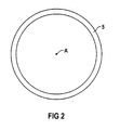
- Tripods 1 and 3 can be digitally controlled by software electric drives in the form of two stepper motors 10, 11 in the rail 5 can be adjusted, the tripods 1, 3 about a vertical axis A of the X-ray system move in a circle.
- Fig. 2 shows the highly schematic guided in a circle around the axis A, mounted on the ceiling D. Rail 5.
- the adjustment of the stands 1, 3 in the rail 5 is in turn controlled by the control computer 7 in such a way that the adjustment of the X-ray source 2 and the X-ray detector 4 is done synchronously and the X-ray source 2 and the X-ray detector 4 relative to one another stay aligned.
- the patient P is on a patient support device in Form of a patient chair 12 stored.
- the patient chair 12 is such in the case of the present embodiment explained that its elements 13, 14 and 15 in known per se Be adjusted by motor relative to each other can.
- the patient P can therefore be in different positions be brought relative to the X-ray device.
- the patient P is fixed on the patient chair 12, so that he was lying on the patient chair 12 during treatment can't change.
- a series of 2D projections of head or Stands 1 and 3 are controlled in the patient's jaw area through the control computer 7 with the stepper motors 10, 11 adjusted synchronously around axis A.
- the X-ray detector 4 is asymmetrical to the X-ray source 2 adjusted.
- the adjustment of the X-ray system taken at different projection angles 2D projections are stored in an image memory 16 of the X-ray device temporarily stored and an image computer 17 provided to generate a 3D image data set.
- the image computer 17 receives directly from the control computer 7.
- the position data of the X-ray source 2 and the X-ray detector 4, which in geometric certain way on the tripods 1, 3 and around Axis A are arranged, the control computer 7 calculates the control data of the stepper motors 10, 11.
- the starting position the X-ray source 2 and the X-ray detector 4 is the control computer 7 from the control data of the vertical adjustment of the telescopic tripods 1, 3 electric drive, from the control data of the stepper motors 10, 11 and from the setting data of the adjusting device 9 known. From the 3D image data set generated in a manner known per se the image calculator can do 17 different 3D images from the head or jaw area of the patient P and on represent a display device 18.
- Based on the 3D images of the patient's head or jaw area P can be an oral surgeon, not shown in FIG. 1 immediately after the image is taken, if necessary on the patient P plan the procedure to be performed. It is advantageous that the location of the generated 3D image data set and the 3D images generated therefrom in the X-ray coordinate system K1 based on the known positions of the x-ray source 2 and the X-ray detector 4 when recording the 2D projections are also known. In this way, the Oral surgeon planning the results directly on the patient P transferred and the procedure immediately on the patient P make. Such planning consists, for example, in determining the location and orientation of a well, which is intended for receiving a pin for a dental implant is. With the help of a 3D image, the doctor can help you Specify the required drilling and then the Drill accordingly on patient P's jaw.
- the spatial relationship between the x-ray device, the patient chair 12 to which the patient P is fixed, and an oral surgery Instrument 27 detects to adjust the patient chair 12 relative to the x-ray device the imaging to adapt accordingly and the instrument 27 in one Show 3D image and navigate relative to patient P. to be able to.
- the navigation system for determining the spatial relationship between the x-ray device, the instrument 27 and the Patient chair 12 and thus that fixed on the patient chair 12 Patient P is in the case of the present embodiment an optical navigation system which cameras 20, 21 and optical reference elements 22 to 25, which on the objects to be detected with regard to their position are arranged in a defined manner and by the cameras 14, 15 are included.
- a computer 26 of the navigation system evaluates those recorded with cameras 20, 21 Images from and can be based on the recorded reference elements 22 to 25 the positions, i.e. H. the locations and orientations of the reference elements 22 to 25 and thus the corresponding one Objects in an arbitrarily selectable reference coordinate system Determine KR.
- the reference element is 22 on the X-ray source 2, the reference element 23 on the X-ray detector 4, the reference element 24 on the element 15 of the patient chair 12 and the reference element 25 on the one to be led by the oral surgeon Instrument 27 arranged.
- the computer 26 can therefore be based on the current positions of the camera images obtained the X-ray source 2, the X-ray detector 4, the element 15 and the instrument 27 in the reference coordinate system Determine KR.
- the calculator 26, which in not shown connected to the image computer 17 the image computer 17 provides the data about the current one Positions of the X-ray source 2, the X-ray detector 4, the element 15, the patient chair 12 and instrument 27 are available.
- the image calculator 17 shows a relationship between the X-ray coordinate system Establish K1 and the reference coordinate system KR and also the coordinates of the 3D image dataset of the reference coordinate system KR. So there is the possibility of changing the position of the patient chair 12 and thus the head of patient P the 3D image data set with the new position of the patient's head P bring in line and also the image representation to adjust accordingly on the display device 18. Becomes the element 15 of the patient chair 12, for example in the course of the train the treatment of the patient P is adjusted relative to the element 14, wherein a change in the position of the patient's head P results, this is registered via the navigation system and the image display can optionally be changed Position of the head of the patient P by the image calculator 17 can be adjusted.
- the navigation system Possibility by determining the position of the instrument 27 relative to the patient chair 12 and thus relative to the Patient P and the 3D image data set in the reference coordinate system KR is an image of the instrument 27 in one with the X-ray device 3D image of the head or jaw area of the patient P and in this way the to support surgical intervention.
- This is special then advantageous if, for example, the tip of the instrument 27 by penetrating the patient's jaw area P is no longer visible during the operation.
- Fig. 3 shows a second, designed according to the invention medical workplace for diagnostics and for surgical Interventions in the mouth, jaw or face area of the Patient P.
- the medical work station shown in FIG. 3 is except for parts of the X-ray device with the in Fig. 1 shown and described above identical in construction and function.
- the X-ray facility shows a medical workplace of the medical work station shown in FIG. 3 suspended from the ceiling about a vertical axis B.
- C-arm 30 on the opposite of each other an X-ray source 2 and an X-ray detector 4 are arranged in a defined manner.
- the central beam ZS one from the X-ray source 2, conical X-ray beam strikes almost in the middle on the input screen of the X-ray detector 4.
- the X-ray detector 4 is via the adjustment device 9 arranged on the C-arm 30 such that it is in the direction of the Central beams ZS adjustable in a geometrically determined way is.
- the C-arm 30 is of telescopic design Bracket 31 arranged on the ceiling D of the treatment room and by means of the control computer, not shown 7 driven electric drives vertically into the Directions of the double arrow b adjustable.
- the control computer 7 32 By means of one too stepper motor controlled by the control computer 7 32 can the C-arm 30 relative to the bracket 31 around the B axis can be pivoted.
- the C-arm 30 is driven by stepper motor 32 pivoted about axis B, one Series of 2D projections at different projection angles is recorded.
- the cached in the image memory 16 The image calculator uses 2D projections 17 are then available together with those from the control computer 7 projection geometries as in the case of the Fig. 1 described embodiment for generating a 3D image data record of the patient's head or jaw area P.
- the control geometries are determined by the control computer 7 from the control data of the stepper motor 32, wherein the starting computer of the X-ray system from the control computer 7 the control data of the stepper motor 32, from the control data of the electric drives of the bracket 31 and the setting data the adjusting device 9 is known.
- the location of the 3D image data set in the X-ray coordinate system K1 is due to the known positions of the x-ray system in the Recording the 2D projections is also known, so that a direct transmission of planning results based on 3D images on the patient P is possible.
- FIG. 4 is a third embodiment of an inventive medical workplace with an x-ray device and a patient positioning device.
- Components of the workplace which are combined with components of the in Fig. 1 workplace shown at least essentially are identical in construction and function, have the same reference numerals Mistake.
- the x-ray device comprises a motor in a rail 50 defines adjustable stand column 51 on which a bracket 52 for receiving a U-shaped carrying device 53 is arranged.
- a bracket 52 for receiving a U-shaped carrying device 53 is arranged on the U-shaped support device 53 .
- the X-ray source 2 and the X-ray detector 4 arranged opposite each other in a defined way, that one originating from the X-ray source 2 Central beam ZS of a conical X-ray beam almost in the middle of the entrance screen of the X-ray detector 4 hits.
- the X-ray detector 4 on the adjustment device 9 arranged on which it towards the Central beam ZS is adjustable adjustable.
- the bracket 52 of the U-shaped carrying device 53 is together with the Carrying device 53 relative to the standing column 51 by at least one essentially horizontally through the U-shaped carrying device extending axis C, which is the so-called Angulation axis acts, swiveling.
- the patient P is lying on a patient bed 60, which a patient support plate 61 and a telescopic column 62 having.
- the telescopic column 62 is also not shown in FIG Way in the rail 50 mounted motor adjustable.
- the carrying device 53 is driven by one controlled by the control computer 7 Stepper motor 54, pivoted about the C axis, being a series 2D projections at different projection angles is recorded.
- the cached in the image memory 16 The image computer 17 then uses 2D projections together with those from the control computer 7 provided projection geometries, which from the control data of the stepping motor 54 can be obtained, as in the case of the in 1 and 3 embodiments shown for generating a 3D image data record of the patient's head or jaw area P.
- the position of the 3D image data set in the X-ray coordinate system K1 is due to the known positions of the X-ray system in turn when recording the 2D projections known. A transfer of those obtained using 3D images Planning results directly on the patient P. therefore possible.
- the image computer 17 based on the position data of the control computer 7 a relationship between the arbitrary selectable coordinate system K1 of the X-ray device and one arbitrarily selectable coordinate system K2 of the patient positioning device even without a navigation system.
- the patient's position can change P by adjusting movements of the patient bed 60 3D image data record from the image computer 17 in accordance be brought with the position of the head of the patient P and the image representation may be adjusted.
- navigation system be present to represent the instrument 27 in 3D images of the mouth or To be able to display the jaw area of patient P.
- the control computer 7 due to the mechanical displacement system the positions of the x-ray device and the patient positioning device are known relative to each other, is sufficient it only the x-ray device or the patient positioning device to be provided with a reference element 22 or 24 in order to the positions of the x-ray device and the patient positioning device in the reference coordinate system KR determine and operate navigation of the instrument 27 can.
- the position data required for this is provided by Computer 26 and the control computer 7 to the image computer 17 Available so that this replica of the instrument 27 in from Show 3D images obtained from the 3D image data record realistically can.
Landscapes
- Health & Medical Sciences (AREA)
- Life Sciences & Earth Sciences (AREA)
- Engineering & Computer Science (AREA)
- Medical Informatics (AREA)
- Heart & Thoracic Surgery (AREA)
- Molecular Biology (AREA)
- Biophysics (AREA)
- Nuclear Medicine, Radiotherapy & Molecular Imaging (AREA)
- Optics & Photonics (AREA)
- Pathology (AREA)
- Radiology & Medical Imaging (AREA)
- Biomedical Technology (AREA)
- Physics & Mathematics (AREA)
- High Energy & Nuclear Physics (AREA)
- Surgery (AREA)
- Animal Behavior & Ethology (AREA)
- General Health & Medical Sciences (AREA)
- Public Health (AREA)
- Veterinary Medicine (AREA)
- Human Computer Interaction (AREA)
- Dentistry (AREA)
- Oral & Maxillofacial Surgery (AREA)
- Apparatus For Radiation Diagnosis (AREA)
- Dental Tools And Instruments Or Auxiliary Dental Instruments (AREA)
Applications Claiming Priority (2)
| Application Number | Priority Date | Filing Date | Title |
|---|---|---|---|
| DE10008053 | 2000-02-22 | ||
| DE10008053A DE10008053A1 (de) | 2000-02-22 | 2000-02-22 | Röntgeneinrichtung und medizinischer Arbeitsplatz für die Diagnostik und für chirurgische Eingriffe im Kopf - und Kiefernbereich eines Patienten |
Publications (3)
| Publication Number | Publication Date |
|---|---|
| EP1127549A2 true EP1127549A2 (fr) | 2001-08-29 |
| EP1127549A3 EP1127549A3 (fr) | 2002-09-18 |
| EP1127549B1 EP1127549B1 (fr) | 2004-06-09 |
Family
ID=7631839
Family Applications (1)
| Application Number | Title | Priority Date | Filing Date |
|---|---|---|---|
| EP01101272A Expired - Lifetime EP1127549B1 (fr) | 2000-02-22 | 2001-01-19 | Appareil de radiographie et poste opérateur pour la diagnose et pour interventions chirurgicales sur la tête et sur la mâchoire d'un patient |
Country Status (4)
| Country | Link |
|---|---|
| US (1) | US6496558B2 (fr) |
| EP (1) | EP1127549B1 (fr) |
| JP (1) | JP2001258876A (fr) |
| DE (2) | DE10008053A1 (fr) |
Cited By (1)
| Publication number | Priority date | Publication date | Assignee | Title |
|---|---|---|---|---|
| US7837385B2 (en) | 2006-08-10 | 2010-11-23 | Siemens Aktiengesellschaft | Method for recording X-ray images by means of a robotically controlled C-arm system and recording device for recording X-ray images |
Families Citing this family (82)
| Publication number | Priority date | Publication date | Assignee | Title |
|---|---|---|---|---|
| US6851851B2 (en) * | 1999-10-06 | 2005-02-08 | Hologic, Inc. | Digital flat panel x-ray receptor positioning in diagnostic radiology |
| US6944262B2 (en) * | 1999-12-01 | 2005-09-13 | Massie Ronald E | Dental and orthopedic densitometry modeling system and method |
| US6381301B1 (en) | 1999-12-01 | 2002-04-30 | Ronald E. Massie | Dental and orthopedic densitometry modeling system and method |
| US8126112B2 (en) * | 1999-12-01 | 2012-02-28 | Massie Ronald E | Osseo classification system and method |
| US8073101B2 (en) * | 1999-12-01 | 2011-12-06 | Massie Ronald E | Digital modality modeling for medical and dental applications |
| JP3926120B2 (ja) * | 2001-02-16 | 2007-06-06 | 株式会社モリタ製作所 | 被写体のx線撮影位置設定手段、この手段を備えたx線撮影装置 |
| DE10130611A1 (de) * | 2001-06-26 | 2003-01-02 | Siemens Ag | Vorrichtung zur Neupositionierung von bildgebenden, digitalen Systemen |
| EP1306053A3 (fr) * | 2001-10-15 | 2004-01-07 | Siemens Aktiengesellschaft | Dispositif de radiographie polyvalent |
| JP2003175027A (ja) * | 2001-12-10 | 2003-06-24 | Hitachi Medical Corp | X線ct装置 |
| EP1474040B1 (fr) * | 2002-02-15 | 2007-10-24 | Breakaway Imaging, Llc | Portique circulaire a segment amovible pour imagerie a rayons x multidimensionnelle |
| DE10211016A1 (de) * | 2002-03-13 | 2003-09-25 | Philips Intellectual Property | Röntgengerät mit lageveränderlichem Röntgendetektor |
| CN100398066C (zh) * | 2002-03-13 | 2008-07-02 | 分离成像有限责任公司 | 准同步多平面x射线成像的系统和方法 |
| EP2915488B1 (fr) | 2002-03-19 | 2019-06-05 | Medtronic Navigation, Inc. | Tomodensitométrie avec un détecteur suivant le mouvement d'une source à rayons x pivotable |
| JP3888203B2 (ja) * | 2002-04-02 | 2007-02-28 | 株式会社島津製作所 | 回診用x線装置 |
| DE10215982A1 (de) * | 2002-04-11 | 2003-11-06 | Siemens Ag | Röntgeneinrichtung |
| DE10216857A1 (de) * | 2002-04-16 | 2003-11-13 | Siemens Ag | Verfahren zur Steuerung einer Röntgeneinrichtung |
| US6966695B2 (en) * | 2002-04-23 | 2005-11-22 | Ge Medical Systems Global Technology Company, Llc | Adjustable patient lateral support |
| DE10224011A1 (de) * | 2002-05-29 | 2003-12-24 | Siemens Ag | Rechnergestütztes Rekonstruktionsverfahren für ein dreidimensionales Objekt |
| US6868138B2 (en) * | 2002-05-29 | 2005-03-15 | The Regents Of The University Of Michigan | Method, processor and computed tomography (CT) machine for generating images utilizing high and low sensitivity data collected from a flat panel detector having an extended dynamic range |
| AU2003245439A1 (en) | 2002-06-11 | 2003-12-22 | Breakaway Imaging, Llc | Cantilevered gantry apparatus for x-ray imaging |
| US7099428B2 (en) * | 2002-06-25 | 2006-08-29 | The Regents Of The University Of Michigan | High spatial resolution X-ray computed tomography (CT) system |
| AU2003262726A1 (en) | 2002-08-21 | 2004-03-11 | Breakaway Imaging, Llc | Apparatus and method for reconstruction of volumetric images in a divergent scanning computed tomography system |
| JP4425792B2 (ja) * | 2002-08-21 | 2010-03-03 | メドトロニック・ナビゲーション・インコーポレーテッド | X線画像化のためのガントリ位置決め装置 |
| US7379524B2 (en) * | 2002-09-13 | 2008-05-27 | Xoran Technologies, Inc. | Computer tomography scanner |
| JP2004136027A (ja) * | 2002-10-21 | 2004-05-13 | Univ Nihon | 画像処理装置 |
| EP1653856A1 (fr) * | 2003-08-07 | 2006-05-10 | Xoran Technologies, Inc. | Systeme d'imagerie peroperatoire |
| CN1933782B (zh) * | 2004-03-23 | 2010-06-16 | 皇家飞利浦电子股份有限公司 | X射线检查设备和方法 |
| JP2006061501A (ja) * | 2004-08-27 | 2006-03-09 | Morita Mfg Co Ltd | X線撮影装置 |
| AU2005285769A1 (en) * | 2004-09-24 | 2006-03-30 | Icat Corporation | Human body information extraction device, human body imaging information reference plane conversion method, and cross section information detection device |
| FI118624B (fi) * | 2005-03-14 | 2008-01-31 | Planmeca Oy | Hammaslääketieteellinen tietokonetomografiakuvantaminen |
| DE102005014188A1 (de) * | 2005-03-29 | 2006-10-12 | Siemens Ag | Vorrichtung für die Aufnahme von Projektionsbildern |
| JP4307406B2 (ja) * | 2005-04-22 | 2009-08-05 | 株式会社モリタ製作所 | 医療用x線撮影装置及びこれに用いるx線検出器 |
| KR100766332B1 (ko) * | 2005-08-08 | 2007-10-11 | 주식회사바텍 | 파노라마, 씨티 및 두부계측 겸용 엑스선 촬영장치 |
| JP4690768B2 (ja) * | 2005-05-13 | 2011-06-01 | 株式会社東芝 | X線診断装置 |
| US7344304B2 (en) * | 2005-06-14 | 2008-03-18 | Varian Medical Systems Technologies, Inc. | Self-alignment of radiographic imaging system |
| JP4632891B2 (ja) * | 2005-07-22 | 2011-02-16 | 株式会社モリタ製作所 | X線ct撮影装置およびx線ct撮影方法 |
| KR100794563B1 (ko) * | 2005-08-08 | 2008-01-17 | 주식회사바텍 | 파노라마 및 씨티 겸용 엑스선 촬영장치 |
| US20080056439A1 (en) * | 2005-10-17 | 2008-03-06 | Imtec Imaging, Llc | Multi-use CT scanning apparatus |
| DK1815794T3 (en) * | 2006-02-01 | 2016-02-01 | Dental Imaging Technologies Corp | Dental X-ray device and method for positioning a patient therein |
| CN100512757C (zh) * | 2006-04-13 | 2009-07-15 | Ge医疗系统环球技术有限公司 | X射线检测设备和x射线成像设备 |
| DE102006021373A1 (de) * | 2006-05-08 | 2007-11-15 | Siemens Ag | Röntgendiagnostikeinrichtung |
| WO2008035828A1 (fr) | 2006-09-22 | 2008-03-27 | Ray Co., Ltd. | Système d'imagerie de complexe dentaire |
| DK2079366T3 (da) * | 2006-10-06 | 2010-11-08 | Nrt Nordisk Roentgen Teknik As | Manipuleringssystem, især et manipuleringssystem til manipulering af et røntgenapparat |
| KR100849144B1 (ko) * | 2006-11-14 | 2008-07-31 | 김익한 | 길이조절이 가능한 아암구조를 갖는 의료용 진단기기 |
| US8290119B2 (en) * | 2007-01-24 | 2012-10-16 | Imaging Sciences International Llc | Adjustable scanner |
| DE102008009643B4 (de) * | 2007-02-22 | 2019-01-24 | J. Morita Manufacturing Corporation | Bildverarbeitungsverfahren, Bildverarbeitungsvorrichtung und Röntgenabbildungsvorrichtung zum Erzeugen eines Panorama-Tomogramms. |
| JP2008229322A (ja) | 2007-02-22 | 2008-10-02 | Morita Mfg Co Ltd | 画像処理方法、画像表示方法、画像処理プログラム、記憶媒体、画像処理装置、x線撮影装置 |
| KR100907821B1 (ko) * | 2007-05-29 | 2009-07-14 | 차영진 | 치과 의료진단용 복합영상 촬영장치 |
| DE102007051719A1 (de) * | 2007-10-30 | 2009-05-07 | Sicat Gmbh & Co. Kg | Schichtaufnahmen zur Implantatplanung |
| FR2924325B1 (fr) * | 2007-12-03 | 2010-11-26 | Trophy | Appareil de radiologie dentaire et procede associe. |
| EP2244636A4 (fr) * | 2008-02-20 | 2011-02-02 | Imaging Sciences Int Llc | Dispositif de balayage réglable |
| FI123978B (fi) * | 2008-06-27 | 2014-01-15 | Planmeca Oy | Hammashoitolaitteisto |
| US8107730B2 (en) * | 2008-08-05 | 2012-01-31 | General Electric Company | Imaging system sag correction method and apparatus |
| US8147139B2 (en) * | 2008-10-13 | 2012-04-03 | George Papaioannou | Dynamic biplane roentgen stereophotogrammetric analysis |
| DE102009031399A1 (de) * | 2009-07-01 | 2011-01-05 | Siemens Aktiengesellschaft | Verfahren und Einrichtung zur Bildunterstützung eines mit einem medizinischen Instrument durchgeführten medizinischen Eingriffes |
| TW201110941A (en) * | 2009-09-25 | 2011-04-01 | Accumis Inc | Image capture system for recording X-ray images in real-time |
| DE102010005633A1 (de) * | 2010-01-25 | 2011-07-14 | Siemens Aktiengesellschaft, 80333 | Röntgeneinrichtung zur Erstellung von 3D-Röntgenbildern eines Untersuchungsobjektes |
| EP2614773B1 (fr) * | 2010-07-13 | 2018-01-03 | Takara Telesystems Corp. | Dispositif d'imagerie de tomogramme à rayons x |
| JP6076822B2 (ja) * | 2012-05-02 | 2017-02-08 | 株式会社モリタ製作所 | X線ct撮影装置 |
| EP2892432B1 (fr) * | 2012-09-07 | 2022-12-28 | Trophy | Appareil pour imagerie de tomographie par ordinateur (ct) partielle |
| CN103654820A (zh) * | 2012-09-11 | 2014-03-26 | 上海联影医疗科技有限公司 | 一种x-射线层析设备模拟装置 |
| JP6218392B2 (ja) * | 2013-02-25 | 2017-10-25 | タカラテレシステムズ株式会社 | パノラマ撮像装置及びパノラマ画像の再構成方法 |
| US9307946B2 (en) | 2013-03-14 | 2016-04-12 | Dental Imaging Technologies Corporation | Ceiling mounted medical imaging system |
| US10004468B2 (en) * | 2013-08-20 | 2018-06-26 | Vatech Co., Ltd. | X-ray imaging device and X-ray imaging method |
| KR20150040768A (ko) | 2013-10-07 | 2015-04-15 | 삼성전자주식회사 | 엑스선 장치 및 엑스선 디텍터 |
| US9808211B2 (en) * | 2013-11-12 | 2017-11-07 | Carestream Health, Inc. | Head and neck imager |
| US10265038B2 (en) * | 2014-01-23 | 2019-04-23 | Vatech Co., Ltd. | X-ray photographing device comprising variable type arm |
| KR20150088679A (ko) * | 2014-01-24 | 2015-08-03 | 주식회사바텍 | Ct 촬영 장치 |
| US10151710B2 (en) * | 2014-07-18 | 2018-12-11 | Peltec Services, Inc. | Portable industrial radiography apparatus |
| US10722200B2 (en) * | 2015-06-04 | 2020-07-28 | Siemens Healthcare Gmbh | Apparatus and methods for a projection display device on X-ray imaging devices |
| US10136870B2 (en) * | 2015-06-11 | 2018-11-27 | Carestream Health, Inc. | Extremity imaging for animals |
| BR112018000628A2 (pt) * | 2015-07-16 | 2018-09-18 | Koninklijke Philips Nv | dispositivo para imageamento por raios x, e sistema para imageamento de raios x |
| US10952689B2 (en) * | 2016-06-10 | 2021-03-23 | Principle Imaging Corporation | Multi-axis linear X-ray imaging system |
| DE102016212467A1 (de) * | 2016-07-08 | 2018-01-11 | Siemens Healthcare Gmbh | Bewegungssteuerung für mobile Röntgeneinrichtung |
| CN110121299A (zh) * | 2016-11-04 | 2019-08-13 | 霍罗吉克公司 | 医学成像装置和操作医学成像装置的方法 |
| DE102016013315B4 (de) | 2016-11-08 | 2024-07-11 | RayScan Technologies GmbH | Messsystem und Verfahren zum Betreiben eines Messsystems |
| US10925562B2 (en) * | 2017-02-22 | 2021-02-23 | General Electric Company | Variable SID imaging |
| EP3403586A1 (fr) * | 2017-05-18 | 2018-11-21 | Koninklijke Philips N.V. | Dispositif et procédé permettant de déterminer des données de positionnement d'un dispositif d'acquisition d'image radiologique sur une unité de support de patient mobile |
| CN108852395A (zh) * | 2018-07-19 | 2018-11-23 | 石家庄华东医疗科技有限公司 | 一种双悬吊dr |
| JP7468373B2 (ja) * | 2021-01-19 | 2024-04-16 | 株式会社島津製作所 | X線撮影装置 |
| IT202200019752A1 (it) * | 2022-09-26 | 2024-03-26 | Enrico Grendene | Metodo e apparato per aumentare la risoluzione spaziale medinate zoom meccanico / ottico in una acquisizione tomografica computerizzata con tecnica cone-beam |
| CN116831613A (zh) * | 2023-08-01 | 2023-10-03 | 有方(合肥)医疗科技有限公司 | 口腔cbct测量设备 |
Citations (2)
| Publication number | Priority date | Publication date | Assignee | Title |
|---|---|---|---|---|
| DE4012627A1 (de) | 1989-09-14 | 1991-03-28 | Instrumentarium Corp | Vorrichtung zur aufnahme raeumlicher roentgenbilder |
| DE19636354A1 (de) | 1996-09-02 | 1998-03-05 | Ruedger Dipl Ing Rubbert | Verfahren und Vorrichtung zur Durchführung von optischen Aufnahmen |
Family Cites Families (12)
| Publication number | Priority date | Publication date | Assignee | Title |
|---|---|---|---|---|
| FR2644590B1 (fr) * | 1989-03-20 | 1994-08-19 | General Electric Cgr Sa | Procede d'acquisition de donnees radiologiques et de reconstruction de structures correspondant a ce corps |
| US5253171A (en) * | 1990-09-21 | 1993-10-12 | General Electric Company | Parallel processing method and apparatus based on the algebra reconstruction technique for reconstructing a three-dimensional computerized tomography (CT) image from cone beam projection data |
| JPH0767870A (ja) * | 1993-09-02 | 1995-03-14 | Sony Corp | 医用検査装置と医用検査装置の患者テーブルの移動検出方法 |
| US5588430A (en) * | 1995-02-14 | 1996-12-31 | University Of Florida Research Foundation, Inc. | Repeat fixation for frameless stereotactic procedure |
| DE19533716A1 (de) * | 1995-09-12 | 1997-03-13 | Siemens Ag | Röntgendiagnostikeinrichtung mit einer Positioniervorrichtung für einen Strahlensender und einen Strahlenempfänger |
| JP3807833B2 (ja) * | 1996-12-10 | 2006-08-09 | 株式会社モリタ製作所 | X線撮影装置 |
| DE19703556A1 (de) | 1997-01-31 | 1998-08-06 | Philips Patentverwaltung | Verfahren und Anordnung zur Positionsbestimmung bei der Röntgenbildgebung |
| US6155713A (en) * | 1997-06-19 | 2000-12-05 | Kabushiki Kaisha Toshiba | X-ray diagnostic apparatus having an X-ray generating portion and an X-ray detecting portion independent of each other |
| JP4402753B2 (ja) * | 1997-06-19 | 2010-01-20 | 株式会社東芝 | X線診断装置 |
| DE19746093C2 (de) | 1997-10-17 | 2002-10-17 | Siemens Ag | C-Bogen-Röntgengerät |
| US6200024B1 (en) * | 1998-11-27 | 2001-03-13 | Picker International, Inc. | Virtual C-arm robotic positioning system for use in radiographic imaging equipment |
| DE19919907C2 (de) * | 1999-04-30 | 2003-10-16 | Siemens Ag | Verfahren und Vorrichtung zur Katheter-Navigation in dreidimensionalen Gefäßbaum-Aufnahmen |
-
2000
- 2000-02-22 DE DE10008053A patent/DE10008053A1/de not_active Withdrawn
-
2001
- 2001-01-19 EP EP01101272A patent/EP1127549B1/fr not_active Expired - Lifetime
- 2001-01-19 DE DE50102504T patent/DE50102504D1/de not_active Expired - Lifetime
- 2001-02-20 JP JP2001043628A patent/JP2001258876A/ja active Pending
- 2001-02-22 US US09/792,120 patent/US6496558B2/en not_active Expired - Lifetime
Patent Citations (2)
| Publication number | Priority date | Publication date | Assignee | Title |
|---|---|---|---|---|
| DE4012627A1 (de) | 1989-09-14 | 1991-03-28 | Instrumentarium Corp | Vorrichtung zur aufnahme raeumlicher roentgenbilder |
| DE19636354A1 (de) | 1996-09-02 | 1998-03-05 | Ruedger Dipl Ing Rubbert | Verfahren und Vorrichtung zur Durchführung von optischen Aufnahmen |
Cited By (1)
| Publication number | Priority date | Publication date | Assignee | Title |
|---|---|---|---|---|
| US7837385B2 (en) | 2006-08-10 | 2010-11-23 | Siemens Aktiengesellschaft | Method for recording X-ray images by means of a robotically controlled C-arm system and recording device for recording X-ray images |
Also Published As
| Publication number | Publication date |
|---|---|
| US6496558B2 (en) | 2002-12-17 |
| EP1127549A3 (fr) | 2002-09-18 |
| EP1127549B1 (fr) | 2004-06-09 |
| US20010036246A1 (en) | 2001-11-01 |
| DE50102504D1 (de) | 2004-07-15 |
| DE10008053A1 (de) | 2001-09-06 |
| JP2001258876A (ja) | 2001-09-25 |
Similar Documents
| Publication | Publication Date | Title |
|---|---|---|
| EP1127549B1 (fr) | Appareil de radiographie et poste opérateur pour la diagnose et pour interventions chirurgicales sur la tête et sur la mâchoire d'un patient | |
| EP1361829B1 (fr) | Dispositif pour piloter des instruments chirurgicaux | |
| EP1246566B1 (fr) | Dispositif pour deplacer de fa on maitrisee un appareil medical | |
| DE3703050C2 (de) | Verfahren zum Röntgen und Vorrichtung zur Durchführung des Verfahrens | |
| DE69823456T2 (de) | Fahrbares Gerät zur biplanaren fluoroskopischen Bilderzeugung | |
| DE10210287B4 (de) | Verfahren und Vorrichtung zur markerlosen Registrierung für navigationsgeführte Eingriffe | |
| DE60128722T2 (de) | Fluoroskopische röntgentomographiebildgebung | |
| EP2337498B1 (fr) | Procédé de réalisation d'un enregistrement radiographique dentaire en 3 dimensions | |
| EP0632995B1 (fr) | Appareil de radiodiagnostic dentaire | |
| DE69831003T2 (de) | Röntgengerät für schädelaufnahmen | |
| DE10215808B4 (de) | Verfahren zur Registrierung für navigationsgeführte Eingriffe | |
| DE102012215922B4 (de) | Medizintechnische Anlage und Verfahren zur Erzeugung von Bildern | |
| DE10003524B4 (de) | Verfahrbares Röntgengerät und Verfahren zur Bestimmung von Projektionsgeometrien | |
| EP1219260A1 (fr) | Procédé et dispositif de traitement dentaire assisté par un système de navigation | |
| EP0142841A2 (fr) | Dispositif limiteur de faisceau pour un appareil de radiodiagnostic | |
| DE10240727A1 (de) | Bildgebendes System und Verfahren zur Optimierung einer Röntgenabbildung | |
| WO2019149400A1 (fr) | Procédé de planification de la position d'un système d'enregistrement d'un appareil d'imagerie médicale, et appareil d'imagerie médicale | |
| DE10057027A1 (de) | Verfahren und Vorrichtung zur Kennzeichnung einer Stelle an einem Untersuchungsobjekt | |
| DE102006001850A1 (de) | Bildgebendes medizintechnisches Gerät | |
| DE10234465A1 (de) | Verfahren zur Schichthöhenpositionierung | |
| DE19951503B4 (de) | Medizinisches System mit einem Bildgebungs- und einem Navigationssystem | |
| EP0681251A2 (fr) | Méthode d'utilisation d'un microscope d'opération | |
| WO2002074500A2 (fr) | Dispositif pour afficher la position spatiale d'un instrument chirurgical pendant une operation | |
| DE102019200591B4 (de) | Schädelklemmvorrichtung zur Fixierung und Ausrichtung eines Kopfes eines Patienten für einen medizinischen Eingriff und medizinisches Bildgebungssystem | |
| DE20205006U1 (de) | Handstück zur Befestigung von Markierungen |
Legal Events
| Date | Code | Title | Description |
|---|---|---|---|
| PUAI | Public reference made under article 153(3) epc to a published international application that has entered the european phase |
Free format text: ORIGINAL CODE: 0009012 |
|
| AK | Designated contracting states |
Kind code of ref document: A2 Designated state(s): AT BE CH CY DE DK ES FI FR GB GR IE IT LI LU MC NL PT SE TR |
|
| AX | Request for extension of the european patent |
Free format text: AL;LT;LV;MK;RO;SI |
|
| PUAL | Search report despatched |
Free format text: ORIGINAL CODE: 0009013 |
|
| AK | Designated contracting states |
Kind code of ref document: A3 Designated state(s): AT BE CH CY DE DK ES FI FR GB GR IE IT LI LU MC NL PT SE TR |
|
| AX | Request for extension of the european patent |
Free format text: AL;LT;LV;MK;RO;SI |
|
| 17P | Request for examination filed |
Effective date: 20021104 |
|
| 17Q | First examination report despatched |
Effective date: 20030116 |
|
| AKX | Designation fees paid |
Designated state(s): DE FR GB IT |
|
| GRAP | Despatch of communication of intention to grant a patent |
Free format text: ORIGINAL CODE: EPIDOSNIGR1 |
|
| GRAS | Grant fee paid |
Free format text: ORIGINAL CODE: EPIDOSNIGR3 |
|
| GRAA | (expected) grant |
Free format text: ORIGINAL CODE: 0009210 |
|
| AK | Designated contracting states |
Kind code of ref document: B1 Designated state(s): DE FR GB IT |
|
| REG | Reference to a national code |
Ref country code: GB Ref legal event code: FG4D Free format text: NOT ENGLISH |
|
| REF | Corresponds to: |
Ref document number: 50102504 Country of ref document: DE Date of ref document: 20040715 Kind code of ref document: P |
|
| REG | Reference to a national code |
Ref country code: IE Ref legal event code: FG4D Free format text: GERMAN |
|
| GBT | Gb: translation of ep patent filed (gb section 77(6)(a)/1977) |
Effective date: 20040712 |
|
| REG | Reference to a national code |
Ref country code: IE Ref legal event code: FD4D |
|
| ET | Fr: translation filed | ||
| PLBE | No opposition filed within time limit |
Free format text: ORIGINAL CODE: 0009261 |
|
| STAA | Information on the status of an ep patent application or granted ep patent |
Free format text: STATUS: NO OPPOSITION FILED WITHIN TIME LIMIT |
|
| 26N | No opposition filed |
Effective date: 20050310 |
|
| REG | Reference to a national code |
Ref country code: FR Ref legal event code: PLFP Year of fee payment: 16 |
|
| REG | Reference to a national code |
Ref country code: DE Ref legal event code: R081 Ref document number: 50102504 Country of ref document: DE Owner name: SIEMENS HEALTHCARE GMBH, DE Free format text: FORMER OWNER: SIEMENS AKTIENGESELLSCHAFT, 80333 MUENCHEN, DE |
|
| REG | Reference to a national code |
Ref country code: FR Ref legal event code: PLFP Year of fee payment: 17 |
|
| REG | Reference to a national code |
Ref country code: FR Ref legal event code: PLFP Year of fee payment: 18 |
|
| PGFP | Annual fee paid to national office [announced via postgrant information from national office to epo] |
Ref country code: DE Payment date: 20190319 Year of fee payment: 19 Ref country code: FR Payment date: 20190124 Year of fee payment: 19 Ref country code: GB Payment date: 20190117 Year of fee payment: 19 Ref country code: IT Payment date: 20190130 Year of fee payment: 19 |
|
| REG | Reference to a national code |
Ref country code: DE Ref legal event code: R119 Ref document number: 50102504 Country of ref document: DE |
|
| GBPC | Gb: european patent ceased through non-payment of renewal fee |
Effective date: 20200119 |
|
| PG25 | Lapsed in a contracting state [announced via postgrant information from national office to epo] |
Ref country code: FR Free format text: LAPSE BECAUSE OF NON-PAYMENT OF DUE FEES Effective date: 20200131 Ref country code: DE Free format text: LAPSE BECAUSE OF NON-PAYMENT OF DUE FEES Effective date: 20200801 Ref country code: GB Free format text: LAPSE BECAUSE OF NON-PAYMENT OF DUE FEES Effective date: 20200119 |
|
| PG25 | Lapsed in a contracting state [announced via postgrant information from national office to epo] |
Ref country code: IT Free format text: LAPSE BECAUSE OF NON-PAYMENT OF DUE FEES Effective date: 20200119 |