EP1127586B1 - Manche destiné à un appareil oculaire à ionophorèse - Google Patents
Manche destiné à un appareil oculaire à ionophorèse Download PDFInfo
- Publication number
- EP1127586B1 EP1127586B1 EP01101307A EP01101307A EP1127586B1 EP 1127586 B1 EP1127586 B1 EP 1127586B1 EP 01101307 A EP01101307 A EP 01101307A EP 01101307 A EP01101307 A EP 01101307A EP 1127586 B1 EP1127586 B1 EP 1127586B1
- Authority
- EP
- European Patent Office
- Prior art keywords
- handle
- region
- housing member
- regions
- flexing
- Prior art date
- Legal status (The legal status is an assumption and is not a legal conclusion. Google has not performed a legal analysis and makes no representation as to the accuracy of the status listed.)
- Expired - Lifetime
Links
- 239000003814 drug Substances 0.000 claims abstract description 19
- 210000004872 soft tissue Anatomy 0.000 claims description 8
- 210000001519 tissue Anatomy 0.000 description 5
- 239000000463 material Substances 0.000 description 2
- 230000000717 retained effect Effects 0.000 description 2
- 241000275455 Idahoa scapigera Species 0.000 description 1
- 210000004204 blood vessel Anatomy 0.000 description 1
- 229940079593 drug Drugs 0.000 description 1
- 210000000744 eyelid Anatomy 0.000 description 1
- 238000003780 insertion Methods 0.000 description 1
- 230000037431 insertion Effects 0.000 description 1
- 230000003993 interaction Effects 0.000 description 1
- 230000013011 mating Effects 0.000 description 1
- 238000012986 modification Methods 0.000 description 1
- 230000004048 modification Effects 0.000 description 1
- 230000003068 static effect Effects 0.000 description 1
- 239000000126 substance Substances 0.000 description 1
Images



Classifications
-
- A—HUMAN NECESSITIES
- A61—MEDICAL OR VETERINARY SCIENCE; HYGIENE
- A61N—ELECTROTHERAPY; MAGNETOTHERAPY; RADIATION THERAPY; ULTRASOUND THERAPY
- A61N1/00—Electrotherapy; Circuits therefor
- A61N1/18—Applying electric currents by contact electrodes
- A61N1/20—Applying electric currents by contact electrodes continuous direct currents
- A61N1/30—Apparatus for iontophoresis, i.e. transfer of media in ionic state by an electromotoric force into the body, or cataphoresis
- A61N1/303—Constructional details
Definitions
- the present invention is directed to ocular iontophoretic apparatuses, and more particularly, to a handle for an ocular iontophoretic apparatus to facilitate the grasping, positioning and placement thereof.
- ocular iontophoretic devices have been known in the art. Such devices as, for example, described in WO-A-99/40967, have been used in an attempt to administer a drug through an electromotive force which drives ionic chemicals through the eye tissue so that they can be absorbed by adjacent tissues and blood vessels.
- the application comprises an iontophoretic apparatus which includes a housing member, a current distribution member, a medicament containment member and a handle member.
- the current distribution member is associated with the housing member.
- the medicament containment member is associated with the current distribution member.
- the handle member is associated with the housing member, and the handle member serves to facilitate the positioning and/or placement of the iontophoretic apparatus.
- the handle member comprises a first handle region and a second handle region extending outwardly from the handle member.
- Each of the first and second handle regions are preferably co-molded with the housing member and distally spaced apart a predetermined distance.
- the first and second handle regions extend away from each other.
- the handle member may be releasably associated with the housing member.
- At least one of the first and second handle regions includes a gripping region.
- the gripping region facilitates the overall gripping of the handle region by a user during the positioning and/or placement of the apparatus.
- the first and second handle regions include a grasping region which joins the handle regions together to, in turn, render a single unitary handle region.
- first and second handle regions include means for flexing the housing member.
- first and second handle regions further include means for limiting the flexing of the housing member.
- the flexing limiting means may comprise the positioning of a portion of the first and second handle regions in a spaced apart orientation. The spaced apart orientation substantially corresponds to the desired maximum flex of the housing member.
- the flexing limiting means further includes means for aligning the first and second handle regions.
- the aligning means precludes inadvertent misalignment of the first and second handle regions during flexing.
- the apparatus further includes means for maintaining the registered placement of the apparatus in the desired orientation.
- the registered placement maintaining means may comprise a receiving region associated with one or both of the handle member and the housing member.
- the receiving region comprises at least one notch.
- the apparatus may further include means for biasing at least a portion of the receiving region against the soft tissue of a user.
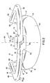
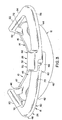
- Iontophoretic apparatus 10 is shown in Figs. 1 and 2 as comprising housing member 12, current distribution member 14, medicament containment member 16 and handle member 18.
- the housing member includes outer surface 40, first end 42, second end 44, upper region 45 and rim 47.
- the housing comprises a plastic material which is molded into a desired configuration for the positioning thereof on the eye of a patient.
- housing member 12 may be of any number of sizes and shapes. Various embodiments of the housing member may include various configurations depending on the medicament to be dispensed, as well as the specific shape of the soft tissue surrounding the eye of the patient, and the particular region of the eye to which it is to be applied. Of course, the handle member is not limited to any particular housing member configurations and may be used with a wide variety of such devices. Additionally, the medicament that is retained in medicament containment member 16 for dispensing is not limited to any particular medicament, and virtually any medicament that can be applied iontophoretically through the eye can be used in association with the iontophoretic apparatus.
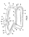
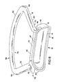
- Handle member 18 is shown primarily in Figs. 1 and 5 as comprising first handle region 20, second handle region 22, means 24 for flexing the handle member, means 26 for limiting the flexing of the handle member and means 25 for maintaining registered placement of the apparatus.
- handle member 18 is co-molded with housing member 12, however, it is likewise contemplated that the handle member may comprise a separate component which may be welded, adhered or otherwise joined to housing member 12.
- the handle member is generally associated with the upper region 45, which, in turn, facilitates placement of the device along, for example, the lower edge of the patient's eye under the lower eyelid. In addition, such handle positioning minimizes the intrusiveness of the handle member and the discomfort to the patient receiving treatment, while maximizing the versatility thereof.
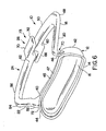
- First handle region 20 of the handle member is shown in Figs. 3 and 4 as including first end 46, second end 48 and first gripping portion 50.
- First end 46 is associated with outer surface 40 proximate first end 42 of the housing member.
- Second end 48 extends outwardly therefrom and in a direction which is generally away from second handle region 22 of the handle member.
- First gripping portion 50 is positioned proximate second end 48 of first handle region 20.
- first gripping portion 50 comprises a region which is sized and shaped so as to promote the gripping thereof by a doctor or other professional during placement of the iontophoretic apparatus in the eye of a patient. As can be seen in Figs.
- first gripping portion 50 is substantially planar and spaced apart from the housing member a distance sufficient to insure that the doctor can easily grip the gripping portion without inadvertently striking or touching the patient.
- the gripping region comprises a substantially flat pod region 51 (Fig. 7).
- second handle region 22 is substantially similar to first handle region 20, and comprises first end 52, second end 54 and second gripping portion 56. While various configurations are contemplated, generally, the first and second handle regions are substantial mirror images of each other (and are substantially symmetrical) about central axis 101 (Fig. 2) of the housing member.
- gripping portion 50 of first handle region 20 and gripping portion 56 of second handle region 22 are integrally associated with each other, to, in turn, define a single loop like configuration for the gripping portion.
- the integrated gripping portion extends from second end 48 of first handle region 20 to second end 54 of second handle region 22.
- the integrated gripping portion is substantially parallel to the housing member and generally follows the surface configuration of the outer surface 40 of housing member 12.
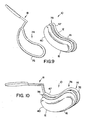
- handle member 18 may be removably associated with housing member 12.
- handle member 18 includes means 74 for releasably retaining the handle member to the housing member.
- Releasable retaining means 74 includes hoop 76 which is releasably positionable within grooved recess 78 of the housing member.
- the handle member can be removed by pulling thereon, to, in turn, release hoop 76 from within recess 78 of the housing member.
- the removable handle member is shown as including a single gripping region, other handle members, including, but not limited to, those shown in Figs. 1, 7 and 8 are likewise contemplated.
- gripping portion 50 of first handle region 20 and gripping portion 56 of second handle region 22 are spaced apart a predetermined distance from each other, to essentially provide a means for flexing the housing.
- the force in turn, flexes the housing member.
- Placement of a gap between the first and second gripping portions defines means 26 for limiting the flexing of the housing member.
- gripping portion 50 and gripping portion 56 extend from the respective second ends of the respective handle regions so as to be substantially parallel to outer surface 40 of housing member 12.
- the two gripping portions essentially extend toward each other until end 62 of first gripping portion 50 is separated from end 64 of second gripping portion 56 by a gap.
- the distance separating the two gripping portions becomes smaller until end 62 of first gripping portion is in abutment with end 64 of second gripping portion 56.
- the respective gripping portions can be pinched no further and additional flexing of the housing member is not possible.
- the flexing limiting means further includes means 32 for aligning the respective ends of the gripping portions.
- aligning means 32 includes first alignment member 68 which is associated with end 60 of gripping portion 50 and second alignment member 70 which is associated with end 62 of gripping portion 52.
- first alignment member 68 which is associated with end 60 of gripping portion 50
- second alignment member 70 which is associated with end 62 of gripping portion 52.
- the alignment members insure that end 60 of gripping portion 50 is aligned with end 62 of gripping portion 52, so that the flexing can be limited by the interaction and abutment of the two ends. Indeed, without the alignment members, inadvertent misalignment of the ends would permit the flexing of the respective ends without limitation and beyond that which is desirable.
- Placement registration means 25 is shown in Fig. 1 as including retaining regions 70, 72 and means 73 for biasing the retaining region against the soft tissue of a patient.
- Retaining region 70 is associated with one or both of first end 46 of first handle region 20 and first end 42 of housing member 12.
- retaining region 72 is associated with one or both of first end 52 of second handle region 22 and second end 44 of housing member 12.
- the retaining regions comprise structures, such as notches that are configured to cooperate with the corner area of the soft tissue surrounding the eye of the user.
- Biasing means 73 comprises the natural resilience of the material surrounding retaining region 70 to return to its original configuration upon flexing thereby biasing the retaining regions against the soft tissue of a patient.
- the corner areas of the eye, the retaining regions and the biasing means cooperate to maintain the registered placement of the apparatus in the desired orientation, and substantially preclude movement of the apparatus once positioned. It is also contemplated that the placement registration means is not limited to cooperation with the corners of the eyes; rather, it can also cooperate with other surrounding tissues that remain substantially static during movement of the eye.
- the electrical leads which attach the power supply to the electrodes which drive the medicament may be molded into the handle member.
- the doctor, physician's assistant or other professional first selects the appropriate apparatus from among various apparatuses of different size, shape and medicament.
- the apparatus is not limited to any particular shape and any particular medicament.
- the doctor first pinches the respective gripping portions 50, 56 toward each other so as to flex housing member 12.
- the user positions the housing member on the surface of the patient's eye.
- the doctor slowly releases the pinching grip on the gripping regions, and housing member 12 returns to its original orientation at which time the entire outer rim 46 is in contact with the surface of the eye.
- the corner regions of the eye are positioned into and accepted by retaining regions 70 and 72 of registered placement maintaining means 25 so as to achieve registered placement of the apparatus in the desired orientation.
- biasing means 73 of registered placement maintaining means 25 cooperates with the retaining regions to bias and, in turn, maintain the corner of the eye and the retaining regions in cooperative engagement.
- the cooperation of the registered placement maintaining means and the biasing means can also compensate for size variation in the dimensions of the soft tissue surrounding the eye.
- biasing means 73 and the flexing means of the handle member may be integrated into a single structure.
- the doctor initiates current delivery from the current distribution member.
- the current forces medicament retained in the medicament containment member through the tissue of the patient's eye.
- the treatment continues for a predetermined period of time which is determined by the type and quantity of medicament that is to be transmitted to the patient.
- the apparatus can be removed from the patient. Specifically, the doctor again grasps the gripping regions of handle member 12 and pulls the housing from the surface of the eye.
- the user pinches gripping portions 50 and 56 until housing member 12 flexes.
- the flexing of the housing member likewise facilitates the release of the housing member from the surface of the eye in a controlled manner.
- the user may individually grasp each of the separate gripping members to release the housing member from the surface of the eye.
- the doctor can grab the unitized gripping member to release the housing member from the surface of the eye.
Landscapes
- Health & Medical Sciences (AREA)
- Public Health (AREA)
- Engineering & Computer Science (AREA)
- Nuclear Medicine, Radiotherapy & Molecular Imaging (AREA)
- Radiology & Medical Imaging (AREA)
- Life Sciences & Earth Sciences (AREA)
- Animal Behavior & Ethology (AREA)
- Biomedical Technology (AREA)
- General Health & Medical Sciences (AREA)
- Veterinary Medicine (AREA)
- Infusion, Injection, And Reservoir Apparatuses (AREA)
- Electrotherapy Devices (AREA)
- Media Introduction/Drainage Providing Device (AREA)
- Medical Preparation Storing Or Oral Administration Devices (AREA)
- Pharmaceuticals Containing Other Organic And Inorganic Compounds (AREA)
- Medicines Containing Material From Animals Or Micro-Organisms (AREA)
- Prostheses (AREA)
Claims (14)
- Appareil d'ionophorèse oculaire, comprenant :un élément formant enveloppe (12) ;un élément distributeur de courant (14) associé à l'élément formant enveloppe (12) ;un élément formant réservoir à médicament (16), associé à l'élément distributeur de courant (14) ; etun élément formant poignée (18) associé à l'élément formant enveloppe (12), l'élément formant poignée (18) facilitant la mise en place, le positionnement, la mise en coïncidence et l'assujettissement de l'appareil d'ionophorèse,
caractérisé en ce quel'élément formant poignée (18) comprend une première région de poignée (20) et une deuxième région de poignée (22) s'étendant vers l'extérieur à partir de l'élément formant poignée (18), la première et la deuxième régions de poignée (20, 22) étant distalement espacées d'une distance prédéterminée. - Appareil selon la revendication 1, caractérisé en ce qu'au moins l'une de la première et la deuxième régions de poignée (20, 22) comprend une région de préhension (50, 56), la région de préhension (50, 56) facilitant la prise en main, par un utilisateur, de la région formant poignée (20, 22).
- Appareil selon la revendication 1, caractérisé en ce que la première et la deuxième régions de poignée (20, 22) sont à distance l'une de l'autre.
- Appareil selon la revendication 1, caractérisé en ce que la première et la deuxième régions de poignée (20, 22) comprennent une région de prise en main (50, 56), qui réunit en une région de poignée monobloc unique les régions de poignée (20, 22).
- Appareil selon la revendication 1, caractérisé en ce que la première et la deuxième régions de poignée (20, 22) comprennent un moyen (24) pour fléchir l'élément formant enveloppe (12).
- Appareil selon la revendication 5, caractérisé en ce que la première et la deuxième régions de poignée (20, 22) comprennent un moyen (26) pour limiter la flexion de l'élément formant enveloppe (12).
- Appareil selon la revendication 6, caractérisé en ce que le moyen limiteur de flexion (26) comprend le positionnement d'au moins une partie de chacune de la première et la deuxième régions de poignée (20, 22) selon une orientation qui les écarte l'une de l'autre, d'une manière correspondant pour l'essentiel à la flexion maximale souhaitée de l'élément formant enveloppe (12).
- Appareil selon la revendication 7, caractérisé en ce que le moyen limiteur de flexion (26) comprend en outre un moyen (32) pour aligner la première et la deuxième régions de poignée (20, 22), pour de ce fait en empêcher un mésalignement par inadvertance.
- Appareil selon la revendication 1, caractérisé en ce que la première et la deuxième régions de poignée (20, 22) sont moulées en même temps que l'élément formant enveloppe (12).
- Appareil selon la revendication 1, caractérisé en ce que l'élément formant poignée (18) est associé d'une manière amovible à l'élément formant enveloppe (12).
- Appareil selon la revendication 1, qui comprend en outre un moyen (25) pour maintenir en place et en coïncidence l'appareil selon l'orientation voulue.
- Appareil selon la revendication 11, caractérisé en ce que le moyen (25) assurant le maintien de la mise en place en coïncidence comprend au moins une région réceptrice (70, 72) associée à au moins l'un de l'élément formant enveloppe (12) et de l'élément formant poignée (18), la région réceptrice (70, 72) étant configurée de façon à coopérer avec une partie du tissu mou d'un utilisateur.
- Appareil selon la revendication 12, caractérisé en ce que la région réceptrice (70, 72) comprend au moins une encoche.
- Appareil selon la revendication 12, qui comprend en outre un moyen (73) pour décaler au moins une partie de la région réceptrice (70, 72) par rapport à une partie du tissu mou d'un utilisateur, pour de ce fait maintenir encore plus sa mise en place en coïncidence à l'intérieur de l'oeil d'un utilisateur.
Applications Claiming Priority (4)
| Application Number | Priority Date | Filing Date | Title |
|---|---|---|---|
| US599245 | 1984-04-11 | ||
| US18449800P | 2000-02-23 | 2000-02-23 | |
| US184498P | 2000-02-23 | ||
| US09/599,245 US6728573B1 (en) | 2000-02-23 | 2000-06-22 | Ocular iontophoretic apparatus handle |
Publications (3)
| Publication Number | Publication Date |
|---|---|
| EP1127586A2 EP1127586A2 (fr) | 2001-08-29 |
| EP1127586A3 EP1127586A3 (fr) | 2001-10-31 |
| EP1127586B1 true EP1127586B1 (fr) | 2005-07-20 |
Family
ID=26880183
Family Applications (1)
| Application Number | Title | Priority Date | Filing Date |
|---|---|---|---|
| EP01101307A Expired - Lifetime EP1127586B1 (fr) | 2000-02-23 | 2001-01-20 | Manche destiné à un appareil oculaire à ionophorèse |
Country Status (6)
| Country | Link |
|---|---|
| US (1) | US6728573B1 (fr) |
| EP (1) | EP1127586B1 (fr) |
| CN (1) | CN1309955A (fr) |
| AT (1) | ATE299735T1 (fr) |
| DE (1) | DE60111971T2 (fr) |
| NZ (1) | NZ508592A (fr) |
Families Citing this family (9)
| Publication number | Priority date | Publication date | Assignee | Title |
|---|---|---|---|---|
| FR2830766B1 (fr) | 2001-10-12 | 2004-03-12 | Optis France Sa | Dispositif de delivrance de medicaments par iontophorese transpalpebrale |
| FR2830767B1 (fr) * | 2001-10-12 | 2004-03-12 | Optis France Sa | Dispositif de delivrance de medicaments par iontophorese ou electroporation introculaire |
| FR2855761B1 (fr) * | 2003-06-03 | 2006-02-24 | Optis France Sa | Dispositif oculaire de delivrance variable de principes actifs par iontophorese |
| US20070260171A1 (en) * | 2005-09-27 | 2007-11-08 | Higuchi John W | Intraocular iontophoretic device and associated methods |
| US8755880B2 (en) * | 2005-10-24 | 2014-06-17 | Aciont, Inc. | Intraocular iontophoretic device and associated methods |
| US8634907B2 (en) * | 2005-10-24 | 2014-01-21 | Aciont, Inc. | Intraocular iontophoretic device and associated methods |
| US8480638B2 (en) * | 2007-10-04 | 2013-07-09 | Aciont, Inc. | Intraocular iontophoretic device and associated methods |
| KR101674904B1 (ko) | 2009-02-26 | 2016-11-10 | 더 유니버시티 오브 노쓰 캐롤라이나 엣 채플 힐 | 중재형 약물전달 시스템과 그 방법 |
| US9320645B2 (en) | 2013-05-29 | 2016-04-26 | Terry Glasser | Approach to administering ocular medication |
Family Cites Families (17)
| Publication number | Priority date | Publication date | Assignee | Title |
|---|---|---|---|---|
| US2525381A (en) | 1947-09-25 | 1950-10-10 | Tower Paul | Contact-type electrode holder |
| US3122137A (en) | 1961-10-30 | 1964-02-25 | Erlanger Gustav | Device for facilitating iontophoresis treatment of eyes |
| US3392725A (en) * | 1966-01-17 | 1968-07-16 | Charles A. Behney | Veterinary ophthalmic applicator |
| JPS61279257A (ja) | 1985-06-05 | 1986-12-10 | 林原 健 | 眉毛発育装置 |
| US5053000A (en) | 1985-11-13 | 1991-10-01 | Imperial Chemical Industries Plc | Ocular treatment |
| US4955378A (en) | 1988-05-02 | 1990-09-11 | University Of South Florida | Apparatus and methods for performing electrofusion at specific anatomical sites |
| US5174304A (en) | 1990-02-16 | 1992-12-29 | Latina Mark A | Electrocycloablation apparatus and method |
| US5169384A (en) | 1991-08-16 | 1992-12-08 | Bosniak Stephen L | Apparatus for facilitating post-traumatic, post-surgical, and/or post-inflammatory healing of tissue |
| DE4127951C2 (de) | 1991-08-23 | 1994-06-09 | Boehringer Ingelheim Kg | Verfahren und Vorrichtung zur gegenfeldkontrollierten Iontophorese |
| US5318514A (en) | 1992-08-17 | 1994-06-07 | Btx, Inc. | Applicator for the electroporation of drugs and genes into surface cells |
| US5618274A (en) * | 1994-04-08 | 1997-04-08 | Rosenthal; Kenneth J. | Method and device for deep pressurized topical, fornix applied "nerve block" anesthesia |
| IT1281159B1 (it) | 1995-05-18 | 1998-02-13 | Giuseppe Bonfiglio | Spazzolino elettronico per ionoforesi dentale |
| US5676648A (en) | 1996-05-08 | 1997-10-14 | The Aps Organization, Llp | Iontophoretic drug delivery apparatus and method for use |
| US5908401A (en) | 1996-05-08 | 1999-06-01 | The Aps Organization, Llp | Method for iontophoretic delivery of antiviral agents |
| FR2773320B1 (fr) | 1998-01-05 | 2000-03-03 | Optisinvest | Dispositif pour le transfert intraoculaire de produits actifs par iontophorese |
| IL123290A (en) | 1998-02-13 | 2001-12-23 | Hadasit Med Res Service | Iontophoretic device |
| US6319240B1 (en) * | 1999-05-25 | 2001-11-20 | Iomed, Inc. | Methods and apparatus for ocular iontophoresis |
-
2000
- 2000-06-22 US US09/599,245 patent/US6728573B1/en not_active Expired - Fee Related
- 2000-12-01 NZ NZ508592A patent/NZ508592A/xx unknown
-
2001
- 2001-01-20 AT AT01101307T patent/ATE299735T1/de not_active IP Right Cessation
- 2001-01-20 DE DE60111971T patent/DE60111971T2/de not_active Expired - Fee Related
- 2001-01-20 EP EP01101307A patent/EP1127586B1/fr not_active Expired - Lifetime
- 2001-02-07 CN CN01102960A patent/CN1309955A/zh active Pending
Also Published As
| Publication number | Publication date |
|---|---|
| DE60111971D1 (de) | 2005-08-25 |
| NZ508592A (en) | 2002-09-27 |
| US6728573B1 (en) | 2004-04-27 |
| EP1127586A3 (fr) | 2001-10-31 |
| CN1309955A (zh) | 2001-08-29 |
| EP1127586A2 (fr) | 2001-08-29 |
| DE60111971T2 (de) | 2006-05-24 |
| ATE299735T1 (de) | 2005-08-15 |
Similar Documents
| Publication | Publication Date | Title |
|---|---|---|
| CN102292031B (zh) | 用于毛发移植的皮肤拉伸器 | |
| EP1127586B1 (fr) | Manche destiné à un appareil oculaire à ionophorèse | |
| US7094053B2 (en) | Custom jig for placing orthodontic brackets and methods of making and using same | |
| JP2802170B2 (ja) | 携帯用のイオン電気導入装置 | |
| US10695508B2 (en) | Reducing pain of skin piercing using vibration | |
| US9750635B2 (en) | Eye injection device | |
| US7666190B2 (en) | Holder of contact lens for vitreous body operation, and holding part and connection part of contact lens for vitreous body operation | |
| CN110522630A (zh) | 用于眼部处理的设备 | |
| US6010488A (en) | Lower eyelid retractor and method for applying medication to the eye | |
| US6952605B1 (en) | Pneumatic release mechanism for a patient contacting article | |
| EP1099432B1 (fr) | Anneau chirurgical de fixation pivotant pour l'utilisation en chirurgie de l'oeil | |
| CN110072495B (zh) | 用于滴注滴眼剂的滴眼剂引导装置 | |
| CA2984327A1 (fr) | Reduction de la douleur du percage de la peau a l'aide de vibrations | |
| US7252655B2 (en) | Ocular iontophoretic apparatus handle | |
| CA2325428A1 (fr) | Manche d'un appareil d'ionophorese oculaire | |
| TW526071B (en) | High current density iontophoretic device and method of use thereof | |
| US12102347B2 (en) | Holder for mounting a handheld tool to a surface | |
| US5772682A (en) | Nose raising orthopedic device | |
| EP3288616B1 (fr) | Réduction de la douleur du perçage de la peau à l'aide de vibrations | |
| US20240299645A1 (en) | Adhesive pad with features to aid application and handling of a medical device | |
| JP3032055U (ja) | 目薬点眼用補助器具 | |
| JP3047825U (ja) | らくらく点眼器 | |
| KR20260064134A (ko) | 점안 보조장치 | |
| CN114366369A (zh) | 口腔内组织切削刀以及切削装置 | |
| HK1249871B (zh) | 使用振动减轻皮肤穿刺的疼痛 |
Legal Events
| Date | Code | Title | Description |
|---|---|---|---|
| PUAI | Public reference made under article 153(3) epc to a published international application that has entered the european phase |
Free format text: ORIGINAL CODE: 0009012 |
|
| AK | Designated contracting states |
Kind code of ref document: A2 Designated state(s): AT BE CH CY DE DK ES FI FR GB GR IE IT LI LU MC NL PT SE TR |
|
| AX | Request for extension of the european patent |
Free format text: AL;LT;LV;MK;RO;SI |
|
| PUAL | Search report despatched |
Free format text: ORIGINAL CODE: 0009013 |
|
| AK | Designated contracting states |
Kind code of ref document: A3 Designated state(s): AT BE CH CY DE DK ES FI FR GB GR IE IT LI LU MC NL PT SE TR |
|
| AX | Request for extension of the european patent |
Free format text: AL;LT;LV;MK;RO;SI |
|
| 17P | Request for examination filed |
Effective date: 20011221 |
|
| AKX | Designation fees paid |
Free format text: AT BE CH CY DE DK ES FI FR GB GR IE IT LI LU MC NL PT SE TR |
|
| 17Q | First examination report despatched |
Effective date: 20040614 |
|
| GRAP | Despatch of communication of intention to grant a patent |
Free format text: ORIGINAL CODE: EPIDOSNIGR1 |
|
| GRAS | Grant fee paid |
Free format text: ORIGINAL CODE: EPIDOSNIGR3 |
|
| GRAA | (expected) grant |
Free format text: ORIGINAL CODE: 0009210 |
|
| AK | Designated contracting states |
Kind code of ref document: B1 Designated state(s): AT BE CH CY DE DK ES FI FR GB GR IE IT LI LU MC NL PT SE TR |
|
| PG25 | Lapsed in a contracting state [announced via postgrant information from national office to epo] |
Ref country code: NL Free format text: LAPSE BECAUSE OF FAILURE TO SUBMIT A TRANSLATION OF THE DESCRIPTION OR TO PAY THE FEE WITHIN THE PRESCRIBED TIME-LIMIT Effective date: 20050720 Ref country code: TR Free format text: LAPSE BECAUSE OF FAILURE TO SUBMIT A TRANSLATION OF THE DESCRIPTION OR TO PAY THE FEE WITHIN THE PRESCRIBED TIME-LIMIT Effective date: 20050720 Ref country code: LI Free format text: LAPSE BECAUSE OF FAILURE TO SUBMIT A TRANSLATION OF THE DESCRIPTION OR TO PAY THE FEE WITHIN THE PRESCRIBED TIME-LIMIT Effective date: 20050720 Ref country code: AT Free format text: LAPSE BECAUSE OF FAILURE TO SUBMIT A TRANSLATION OF THE DESCRIPTION OR TO PAY THE FEE WITHIN THE PRESCRIBED TIME-LIMIT Effective date: 20050720 Ref country code: CH Free format text: LAPSE BECAUSE OF FAILURE TO SUBMIT A TRANSLATION OF THE DESCRIPTION OR TO PAY THE FEE WITHIN THE PRESCRIBED TIME-LIMIT Effective date: 20050720 Ref country code: BE Free format text: LAPSE BECAUSE OF FAILURE TO SUBMIT A TRANSLATION OF THE DESCRIPTION OR TO PAY THE FEE WITHIN THE PRESCRIBED TIME-LIMIT Effective date: 20050720 Ref country code: FI Free format text: LAPSE BECAUSE OF FAILURE TO SUBMIT A TRANSLATION OF THE DESCRIPTION OR TO PAY THE FEE WITHIN THE PRESCRIBED TIME-LIMIT Effective date: 20050720 |
|
| REG | Reference to a national code |
Ref country code: GB Ref legal event code: FG4D |
|
| REG | Reference to a national code |
Ref country code: CH Ref legal event code: EP |
|
| REG | Reference to a national code |
Ref country code: IE Ref legal event code: FG4D |
|
| REF | Corresponds to: |
Ref document number: 60111971 Country of ref document: DE Date of ref document: 20050825 Kind code of ref document: P |
|
| PG25 | Lapsed in a contracting state [announced via postgrant information from national office to epo] |
Ref country code: DK Free format text: LAPSE BECAUSE OF FAILURE TO SUBMIT A TRANSLATION OF THE DESCRIPTION OR TO PAY THE FEE WITHIN THE PRESCRIBED TIME-LIMIT Effective date: 20051020 Ref country code: SE Free format text: LAPSE BECAUSE OF FAILURE TO SUBMIT A TRANSLATION OF THE DESCRIPTION OR TO PAY THE FEE WITHIN THE PRESCRIBED TIME-LIMIT Effective date: 20051020 Ref country code: GR Free format text: LAPSE BECAUSE OF FAILURE TO SUBMIT A TRANSLATION OF THE DESCRIPTION OR TO PAY THE FEE WITHIN THE PRESCRIBED TIME-LIMIT Effective date: 20051020 |
|
| PG25 | Lapsed in a contracting state [announced via postgrant information from national office to epo] |
Ref country code: PT Free format text: LAPSE BECAUSE OF FAILURE TO SUBMIT A TRANSLATION OF THE DESCRIPTION OR TO PAY THE FEE WITHIN THE PRESCRIBED TIME-LIMIT Effective date: 20051221 |
|
| PG25 | Lapsed in a contracting state [announced via postgrant information from national office to epo] |
Ref country code: IE Free format text: LAPSE BECAUSE OF NON-PAYMENT OF DUE FEES Effective date: 20060120 |
|
| PG25 | Lapsed in a contracting state [announced via postgrant information from national office to epo] |
Ref country code: MC Free format text: LAPSE BECAUSE OF NON-PAYMENT OF DUE FEES Effective date: 20060131 Ref country code: LU Free format text: LAPSE BECAUSE OF NON-PAYMENT OF DUE FEES Effective date: 20060131 |
|
| REG | Reference to a national code |
Ref country code: CH Ref legal event code: PL |
|
| NLV1 | Nl: lapsed or annulled due to failure to fulfill the requirements of art. 29p and 29m of the patents act | ||
| ET | Fr: translation filed | ||
| PLBE | No opposition filed within time limit |
Free format text: ORIGINAL CODE: 0009261 |
|
| STAA | Information on the status of an ep patent application or granted ep patent |
Free format text: STATUS: NO OPPOSITION FILED WITHIN TIME LIMIT |
|
| 26N | No opposition filed |
Effective date: 20060421 |
|
| REG | Reference to a national code |
Ref country code: IE Ref legal event code: MM4A |
|
| PGFP | Annual fee paid to national office [announced via postgrant information from national office to epo] |
Ref country code: DE Payment date: 20080117 Year of fee payment: 8 Ref country code: GB Payment date: 20080116 Year of fee payment: 8 Ref country code: IT Payment date: 20080131 Year of fee payment: 8 |
|
| PGFP | Annual fee paid to national office [announced via postgrant information from national office to epo] |
Ref country code: FR Payment date: 20080108 Year of fee payment: 8 |
|
| PG25 | Lapsed in a contracting state [announced via postgrant information from national office to epo] |
Ref country code: CY Free format text: LAPSE BECAUSE OF FAILURE TO SUBMIT A TRANSLATION OF THE DESCRIPTION OR TO PAY THE FEE WITHIN THE PRESCRIBED TIME-LIMIT Effective date: 20050720 |
|
| PG25 | Lapsed in a contracting state [announced via postgrant information from national office to epo] |
Ref country code: ES Free format text: LAPSE BECAUSE OF NON-PAYMENT OF DUE FEES Effective date: 20060131 |
|
| GBPC | Gb: european patent ceased through non-payment of renewal fee |
Effective date: 20090120 |
|
| PG25 | Lapsed in a contracting state [announced via postgrant information from national office to epo] |
Ref country code: DE Free format text: LAPSE BECAUSE OF NON-PAYMENT OF DUE FEES Effective date: 20090801 |
|
| REG | Reference to a national code |
Ref country code: FR Ref legal event code: ST Effective date: 20091030 |
|
| PG25 | Lapsed in a contracting state [announced via postgrant information from national office to epo] |
Ref country code: GB Free format text: LAPSE BECAUSE OF NON-PAYMENT OF DUE FEES Effective date: 20090120 |
|
| PG25 | Lapsed in a contracting state [announced via postgrant information from national office to epo] |
Ref country code: FR Free format text: LAPSE BECAUSE OF NON-PAYMENT OF DUE FEES Effective date: 20090202 |
|
| PG25 | Lapsed in a contracting state [announced via postgrant information from national office to epo] |
Ref country code: IT Free format text: LAPSE BECAUSE OF NON-PAYMENT OF DUE FEES Effective date: 20090120 |