EP1127600A2 - Flugkreisel - Google Patents
Flugkreisel Download PDFInfo
- Publication number
- EP1127600A2 EP1127600A2 EP01104707A EP01104707A EP1127600A2 EP 1127600 A2 EP1127600 A2 EP 1127600A2 EP 01104707 A EP01104707 A EP 01104707A EP 01104707 A EP01104707 A EP 01104707A EP 1127600 A2 EP1127600 A2 EP 1127600A2
- Authority
- EP
- European Patent Office
- Prior art keywords
- gravity
- center
- flat body
- game device
- extension
- Prior art date
- Legal status (The legal status is an assumption and is not a legal conclusion. Google has not performed a legal analysis and makes no representation as to the accuracy of the status listed.)
- Withdrawn
Links
- 230000005484 gravity Effects 0.000 claims abstract description 24
- 238000013519 translation Methods 0.000 claims abstract description 9
- 238000000034 method Methods 0.000 claims abstract description 7
- 230000002093 peripheral effect Effects 0.000 claims description 11
- 230000000087 stabilizing effect Effects 0.000 claims description 6
- 238000009987 spinning Methods 0.000 claims description 2
- 238000004519 manufacturing process Methods 0.000 description 6
- 230000000694 effects Effects 0.000 description 4
- 230000007704 transition Effects 0.000 description 4
- 230000002349 favourable effect Effects 0.000 description 3
- 210000001145 finger joint Anatomy 0.000 description 3
- 239000000463 material Substances 0.000 description 3
- 239000004033 plastic Substances 0.000 description 3
- 230000006641 stabilisation Effects 0.000 description 3
- 238000011105 stabilization Methods 0.000 description 3
- 208000030470 Trigger Finger disease Diseases 0.000 description 2
- 230000001133 acceleration Effects 0.000 description 2
- 238000004040 coloring Methods 0.000 description 2
- 239000002985 plastic film Substances 0.000 description 2
- 229920006255 plastic film Polymers 0.000 description 2
- 238000013459 approach Methods 0.000 description 1
- 230000001174 ascending effect Effects 0.000 description 1
- 238000010276 construction Methods 0.000 description 1
- 238000001816 cooling Methods 0.000 description 1
- 230000006378 damage Effects 0.000 description 1
- 238000013461 design Methods 0.000 description 1
- 238000011161 development Methods 0.000 description 1
- 239000000975 dye Substances 0.000 description 1
- 238000005516 engineering process Methods 0.000 description 1
- 230000024703 flight behavior Effects 0.000 description 1
- 230000000977 initiatory effect Effects 0.000 description 1
- 238000001746 injection moulding Methods 0.000 description 1
- 239000013067 intermediate product Substances 0.000 description 1
- 230000005923 long-lasting effect Effects 0.000 description 1
- 239000000123 paper Substances 0.000 description 1
- 230000000737 periodic effect Effects 0.000 description 1
- 230000010363 phase shift Effects 0.000 description 1
- 231100000614 poison Toxicity 0.000 description 1
- 239000002994 raw material Substances 0.000 description 1
- 230000003716 rejuvenation Effects 0.000 description 1
- 238000011160 research Methods 0.000 description 1
- 230000000284 resting effect Effects 0.000 description 1
- 230000009528 severe injury Effects 0.000 description 1
- 239000003381 stabilizer Substances 0.000 description 1
- 238000010408 sweeping Methods 0.000 description 1
- 239000003440 toxic substance Substances 0.000 description 1
- 238000012549 training Methods 0.000 description 1
Images
Classifications
-
- A—HUMAN NECESSITIES
- A63—SPORTS; GAMES; AMUSEMENTS
- A63H—TOYS, e.g. TOPS, DOLLS, HOOPS OR BUILDING BLOCKS
- A63H33/00—Other toys
- A63H33/18—Throwing or slinging toys, e.g. flying disc toys
-
- A—HUMAN NECESSITIES
- A63—SPORTS; GAMES; AMUSEMENTS
- A63H—TOYS, e.g. TOPS, DOLLS, HOOPS OR BUILDING BLOCKS
- A63H27/00—Toy aircraft; Other flying toys
- A63H27/12—Helicopters ; Flying tops
Definitions
- the invention relates to a toy in the form of a flying spinning top consisting of a flat body with at least one area close to the center of gravity and at least one extension, which has a free end, and a method for Starting the same.
- Boomerangs are like "frisbee" slices with one hand on their periphery gripped and then sweeping by a powerful arm movement flung away, this due to the momentum given in one for the Flight stabilization can be offset important, fast rotation. It can be done do not avoid giving the aircraft a big impulse, so that it flies away at high speed and when it hits a Obstacle can cause severe damage or even destroy it would.
- the feature of claim 2 leads to the fact that the limited tangential speed of a snapping finger and the circumferential rotational speed of the aircraft that can be generated thereby can be converted into a rotational speed ⁇ that is approximately the same or preferably greater than the rotational speed of the snapping finger tip.
- Claim 3 specifies this design rule; With the preferred distance range, there is in particular a favorable ratio between v R / v T >> 1. This enables the desired speed range to be reached effortlessly; at high speeds there is also the effect that the eye can no longer follow the rotating parts and instead perceives a circular disc, which gives the impression of a flying toy UFO, which is particularly popular with children.
- the feature according to claim 4 facilitates the start of the game device according to the invention when it can be supported with low friction in the area of its center of gravity.
- Claims 5 and 6 form a compromise with regard to favorable snap-on properties on the one hand and an air cushion that is as stable as possible during the flight on the other hand.
- rotation about other axes is also avoided by the air resistance and thereby a stable position is ensured, so that such an aircraft is stable even at low rotational speed ⁇ remains.
- the aim of claim 8 is to avoid both potentially injuring edge areas and notches that reduce mechanical stability.
- the extension in question has an exposed area in the area of its rear edge, where the snap-on force can act tangentially and is thus optimally converted into a rotational movement, so that the reported translation speed can be reduced to a minimum.
- the invention further provides that the flat body has a thickness of 0.1 to 3 mm, preferably 0.2 to 1 mm, in particular 0.3 to 0.7 mm.
- the strength required results primarily from the stability requirements for the Aircraft according to the invention and possibly from manufacturing factors.
- a lighter, more stable is preferably suitable for the aircraft according to the invention Material, especially plastic.
- a plastic is also without any further treatment is already corrosion-free, so that the manufacturing costs to a Minimum are lowered. Since the desired coloring is already achieved by adding Dyes can be set in the granular raw material, for example no subsequent coloring is required.
- a suitable one Material can also be ensured that no toxic substances are included and therefore there is no danger for children playing, even if they try to put such a toy in their mouth. Beyond that however, the diameter of the body according to the invention is deliberately dimensioned in such a way that it cannot be swallowed.
- the invention also offers the possibility that the flat body together with the molded, wing-like extensions made of a rigid film or a rigid cardboard manufactured, in particular punched out.
- This manufacturing process is already going from a film-like or sheet-like intermediate product, so that the further Process steps can be carried out with simple tools and thus allow a particularly cost-effective production. Because of this Manufacturing process, a total weight of less than 1 g can be realized.
- wing-like extension (s) are extends approximately radially away from the center of gravity of the flat body take advantage of the fact that the shortest connection between two points is a Is straight. Since the wing-like extensions run approximately radially, one with lowest material expenditure and therefore with a lowest moment of inertia Connection of the wing periphery to the area of the missile close to the center of gravity created.
- the invention allows further development in that the wing-like or wing-like Extensions has a base with a curved circumference (s).
- the wing-like extensions are bent, for example in their peripheral area, the The buoyancy generated there is increased because the bent wing areas are a Extend the wing cross section there.
- the inclination of an extension in relation to the base plane of the flat body can be between 2 ° and 30 °, preferably between 3 ° and 20 °, especially between 5 ° and 15 °.
- the inclination of the wing-like extension (s) with respect to the base plane of the flat body can be produced by deformation of the plastic film. This can be accomplished, for example, by the already punched out body at least partially heated and thus temporarily in a plastic state is brought, and in the subsequent cooling in the shape in question is forced. On the other hand, any shape can also be made using injection molding technology getting produced.
- the flight characteristics of the gaming device according to the invention depend on a large number on boundary conditions, since in particular fluidic factors are taken into account. Therefore, not every conceivable circumferential shape is flat Body with a wing-like extension placed on it already airworthy.
- the Based on further research, the inventor has different categories of Missiles constructed, which thanks to their circumferential shape particularly favorable Have flight characteristics.
- a first embodiment is a second, in the preferred direction of rotation by about 10 ° to 120 °, preferably 20 ° to 90 °, in particular 30 ° to 60 ° planar extension provided at the rear.
- This extension serves the Stabilization of the position of the actual, preferably longer Buoyancy wing and therefore ensures stable flight behavior of the same.
- This Embodiment has the advantage that only one lift wing and one additional stabilizing wings are necessary so that the moment of inertia continues is reduced. A big one can be on the comparatively long lift wing Attack torque, making this arrangement in a particularly strong Rotational movement can be offset at the start of a large quantum Is able to absorb rotational energy and is therefore particularly long in the Can hold air.
- Another type of airworthy play equipment is characterized by several, wing-like Appendages that are rotationally symmetrical around the center of gravity of the flat body or arranged in mirror image to an axis passing through its center of gravity are.
- the aircraft receives through a symmetrical Geometry stable flight characteristics, while at the same time a convenient location of the Center of gravity is reached approximately in the middle of the flat body.
- the flight characteristics of the rotationally symmetrical embodiment can be further perfect the wing-like extensions by identical angles strive away from the center of gravity of the flat body. It This results in an approximately star-shaped arrangement, with the individual rays but can also follow a curved course.
- the central area does not produce a buoyancy effect, can be provided here a central recess encompassing the focus, which is surrounded by a closed ring of the flat body. Because of this closed ring connecting and stabilizing the different, wing-like The central region can be omitted as largely force-free be, which further reduces the moment of inertia of the arrangement. Further this ring-like construction offers the possibility of largely individual wings to decouple from each other, since their connection only over the small cross section of the Ring takes place so that the inclination of a wing is brought about with the simplest of means can be.
- the number of waves of the closed ring By making the number of waves of the closed ring the number of wing-like Extensions can be caused by a phase shift of the wing attachment points compared to the waves of the closed ring the angle of inclination of the attached, wing-like elements can be adjusted. A deformation of the Wing-like elements themselves are then unnecessary, so that even with simple Manufacturing devices a high symmetry of the arrangement can be achieved.
- the flat body with its focus area on a convex surface, especially one Knuckles or the like, placed and then with a finger approximately horizontally against flipped an extension of the flat body so that it rotates rapidly is displaced and a gyroscopic force stabilizing the position and, if necessary, by propeller-like effect of the extension (s) experiences a load-bearing vertical force and due to an approximately horizontal acceleration force.
- This procedure is for the operation of the flight gyro in closed rooms customized. Since a particularly slow translation movement is desired the flight gyro according to the invention only at a peripheral end flipped and experiences a very high torque rapid rotational movement, while the horizontally acting acceleration force, which results in a translational movement is comparatively small. This will achieved by the distinctive, wing-like shape of the parts generating the buoyancy of the flat body, which has the lowest possible moment of inertia pull.
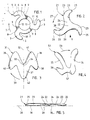
- the gyroscope 1 is shown in its original size in FIG. 1. He is from one Plastic film made with a thickness of about 0.2 mm and therefore ultralight; his Weight is only about 0.5 g. It has an annular body 2 with three with respect to the center of the ring, offset by 120 °, wing-like Extensions 3. Like the ring 3, the wing-like extensions 3 also have a width about 0.6 - 1.0 cm. The wing-like extensions 3 run in their Bend transition area 4 radially outwards with respect to ring 2 however then gradually around 90 ° and run in its outer area then approximately coaxial to the ring 2. They finally each end in a wing tip 5, which is delimited by an approximately semicircular curve. The gyroscope 1 has one preferred direction of rotation 7, which is approximately from the free end 5 of a wing 3 whose starting point 4 is directed.
- the entire boundary line 6 of the missile 1 is extremely smooth and is in the transition areas 4 in particular, so that there is none at all Notches impairing stability exist.
- the ring 2 is along its circumference corrugated with a periodic, approximately sinusoidal amplitude, one Wave period corresponds to a third of the ring circumference, making a total of three Waves are formed along its circumference.
- the corrugation of ring 2 is phase-shifted with respect to the wings 3 such that in the direction of rotation 7 at the front 8 of each wing-like approach 3 a maximum 9 each Wave amplitude, while on the wing back 10 the following Minimum is 11.
- the ring 2 is within the transition areas 4 inclined downwards from the wing front 8 to the rear 10 thereof, and this Inclination divides the otherwise just formed wing 3 into it Top area 5 with.
- Rotates the gyro 1 at high speed in the direction arrow 7, the wing-like extensions 3 displace the cut air below, whereby at the same time the gyroscope 1 has an opposite direction
- Experiences buoyancy Due to the extremely light weight of the gyroscope 1 and its extremely small cross-section can therefore remain in the air for a very long time hold and steadily increase in height even over a long period of time.
- the central recess 12 within the ring 2 has in the illustrated Embodiment has a diameter of about 22 mm, so that the center this recess 12 located center of gravity only about 11 mm from the nearest boundary line 13 is located. Therefore, the gyroscope 1 with its annular area 2 on a palm, in particular on a Knuckles or on an angled finger joint, are placed and is additionally centered. Then one finger of the other Hand flipped against one of the free ends 5 of the wing-like extensions 3, whereby the gyroscope 1 can be made to rotate rapidly.
- the gyroscope 1 If the gyroscope 1 is placed on a flat surface for take-off, then a part becomes the energy absorbed by the flicking into a translational movement implemented so that the gyroscope 1 at about constant speed, because of the low air resistance hardly slowed down, flies away. If the gyroscope 1 on the other hand, with its central recess 12 via an angled finger joint put on, so he can not fly away while flipping, but he receives only a quick rotation, and then it rises vertically similarly a helicopter up.
- the embodiment 21 of a gyro differs from the embodiment 1 mainly in that the central Body is not ring-shaped but approximately disc-shaped. From this central area 22 then again protrude three wings 23, offset from each other by 120 ° each Outside. The wings 23 diverging apart in a star shape are in turn of theirs in the area of the respective attachment point 24 approximately radially directed longitudinal axis up to an approximately tangential axis direction in the region of its peripheral ends 25 bent.
- the boundary line 26 is completely rounded, so that no notches affect the stability of the gyro 21.
- the preferred Direction of rotation 27 also extends from the wing ends 25 to the front ends arranged starting points 24.
- the wings 23 are also here inclined with respect to the base plane 28 of the gyroscope 21.
- This is done by a Corresponding corrugation of the central area 22 in particular on the Starting points 24 reached.
- This corrugation is such that the wings 23 of their in Direction of rotation 27 front edge 29 up to its rear edge 30 run downwards.
- 27 of the Flight gyroscope 21 accelerates the air molecules downwards and consequently experiences them the gyroscope 21 has a buoyancy which gives it optimal flight characteristics.
- the gyro 21 it is the case with the gyro 21 not possible to do this when starting, for example on a finger joint or the like center, so that when flicking it is always in addition to the rotary movement receives a translational movement.
- the gyroscope 31 has one instead of one Central axis 32 symmetrical basic shape. This results from the fact that on a three disk-shaped central bodies 34 located near the center of gravity 33 different wings 35 - 37 are formed. While the two wings 35, 36 have an angled shape and in the area of one of their legs are molded onto the central body 34, the third wing 37 has the shape of a triangle, which is formed with one side on the central region 34. Cross-sectional thickness, Diameter and weight correspond approximately to the embodiments 1, 21. All wings 35, 36, 37 are surrounded by a rounded boundary line 38 surround.
- the preferred direction of rotation 39 of this gyro 31 corresponds to this Clockwise, and consequently the vanes 35-37 are opposite to this direction of rotation 39 each inclined downwards to achieve the length required for a long flight To generate lift.
- the inclination of the wings 35-37 is relatively flat and lies approximately between 5 ° and 15 °.
- this gyroscope 31 can be thanks to its differently designed wings 35 - 37 in different places 40 - 42 snap on the different distances to the center of gravity 33 exhibit.
- the given energy is given the same starting impulse each differently divided into rotational and translational movements, so that it it is possible, as desired, a slow and ascending flight as well as one fast and sinking flat due to the low rotation speed To realize flight.
- the embodiment of the gyro 51 according to FIG. 4 is complete constructed asymmetrically.
- You can roughly this embodiment characterize that of a ring segment-shaped central part 52 which is approximately one Includes center angle of 60 °, a front lying in the direction of rotation 53 Main wing 54 protrudes approximately vertically, one against the direction of rotation 53 about 30 ° set back secondary wing 55 is assigned, and again by about 30 ° displaces a third control or stabilizing wing 56.
- the secondary wing 55 has about 80-90% of the area of the main wing 54
- the control wing 57 is included an area of about 10-20%, on the other hand, is comparatively small.
- the main wing 54 can be used for maximum lift be formed, and the control wing 56 provides similar to the horizontal stabilizer Aircraft for a stable attitude, while the secondary wing 55 preferred to Snap-on can be used and is optimized for this purpose.
- the Ratio of the lengths of the main wing 54 and the secondary wing 55 can thus preferred flight speed of this gyro 51 can be set. It has showed that with a wing length ratio of about 5: 4 optimal Allow long-range properties to be achieved.
Landscapes
- Toys (AREA)
Abstract
Description
- Fig. 1
- eine Draufsicht auf eine erste Ausführungsform der Erfindung;
- Fig. 2
- eine zweite Ausführungsform der Erfindung in einer der Fig. 1 entsprechenden Darstellung;
- Fig. 3
- eine weitere Ausführungsform der Erfindung in einer Ansicht gemäß Fig. 1;
- Fig. 4
- eine wiederum abgewandelte Ausführungsform der Erfindung in der selben Ansicht wie Fig. 1; sowie
- Fig. 5
- eine Ansicht auf die Fig. 2 in Richtung des Pfeils V.
Claims (10)
- Spielgerät in Form eines Flugkreisels (1;21;31;51), bestehend aus einem flächigen Körper (2,3;22,23;34,35;52,54-56) mit wenigstens einem schwerpunktnahen Bereich und wenigstens einem Fortsatz (3;23;35;54-56), der ein freies Ende (5;25;35) aufweist, dadurch gekennzeichnet, dass der maximale Abstand r des Umfangsrandes von dem Schwerpunkt (33), die Masse m und das Trägheitsmoment des flächigen Körpers (2,3;22,23;34,35;52,54-56) derart bemessen sind, dass dieser mit seinem schwerpunktnahen Bereich (2;22;34;52) auf eine konvex gewölbte Oberfläche, insbesondere einen Fingerknöchel od. dgl., gelegt werden kann und sodann durch horizontales, tangentiales Anschnippen mit einem Finger etwa gegen das freie Ende (5;25;35) eines Fortsatzes (3;23;35;54-56) in eine schnelle Rotationsbewegung ω (ω ≥ 300 U/min) (7;27;39;53) bei gleichzeitig langsamer Translationsbewegung vT (vT ≤ ω * r) versetzbar ist und dadurch eine die Lage stabilisierende Kreiselkraft erfährt, so dass er horizontal ausgerichtet bleibt und aufgrund seiner flächigen Gestalt während seines Fluges von einem Luftkissen getragen wird.
- Spielgerät nach Anspruch 1, dadurch gekennzeichnet, dass der Abstand r des freien Endes (5;25;35) eines zum Anschnippen vorgesehenen Fortsatzes (3;23;35;54-56) von dem Schwerpunkt (33) kleiner ist als die durchschnittliche Länge des Zeige- oder Mittelfingers einer anschnippenden Person.
- Spielgerät nach Anspruch 1 oder 2, dadurch gekennzeichnet, dass der Abstand r des freien Endes (5;25;35) eines zum Anschnippen vorgesehenen Fortsatzes (3;23;35;54-56) von dem Schwerpunkt (33) zwischen 1,5 cm und 8 cm, vorzugsweise zwischen 2,0 cm und 6,5 cm liegt, insbesondere zwischen 2,5 und 5,0 cm liegt.
- Spielgerät nach einem der vorhergehenden Ansprüche, dadurch gekennzeichnet, dass der Schwerpunkt (33) des flachen Körpers (2,3;22,23;34,35;52,54-56) innerhalb desselben (schwerpunktnaher Bereich (2;22;34;52)) oder in einem Abstand von nicht mehr als 2 cm, vorzugsweise nicht mehr als 1,5 cm, insbesondere nicht mehr als 1,2 cm von diesem liegt.
- Spielgerät nach einem der vorhergehenden Ansprüche, dadurch gekennzeichnet, dass der Radius eines um den flachen Körper (2,3;22,23;34,35;52,54-56) umbeschriebenen Minimalkreises zwischen 1,5 und 8 cm, vorzugsweise zwischen 2 und 6 cm, insbesondere zwischen 2,5 und 4 cm liegt.
- Spielgerät nach einem der vorhergehenden Ansprüche, dadurch gekennzeichnet, dass die Fläche des flachen Körpers zwischen 20 % und 60 %, vorzugsweise zwischen 25 % und 55 %, insbesondere zwischen 30 % und 50 % der Fläche eines um den flachen Körper (2,3;22,23;34,35;52,54-56) umbeschriebenen Minimalkreises aufweist.
- Spielgerät nach einem der vorhergehenden Ansprüche, gekennzeichnet durch drei oder mehr angeformte Fortsätze (3;23;35;54-56).
- Spielgerät nach einem der vorhergehenden Ansprüche, dadurch gekennzeichnet, dass die Grundfläche des flachen Körpers (2,3;22,23;34,35;52,54-56) samt aller angeformter Fortsätze (3;23;35;54-56) von einer glatten Kurve (6,13;26;38) begrenzt wird, wobei die freien Enden (5;25;35) der Fortsätze (3;23;35;54-56) durch konvexe Kurvenabschnitte berandet sind, die durch wenigstens je einen konkaven Kurvenabschnitt voneinander getrennt sind.
- Spielgerät nach einem der vorhergehenden Ansprüche, dadurch gekennzeichnet, dass im Bereich der in der bevorzugten Rotationsrichtung rückwärtigen Kante eines zum Anschnippen vorgesehenen Fortsatzes (3;23;35;54-56) eine Tangente an den Umfangsrand des flächigen Körpers (2,3;22,23;34,35;52,54-56) existiert, die durch den Schwerpunkt (33) läuft oder in Rotationsrichtung des betreffenden Fortsatzes (3;23;35;54-56) vor dem Schwerpunkt (33) vorbeiläuft.
- Verfahren zum Starten eines Flugkreisels (1;21;31;51) nach einem der vorhergehenden Ansprüche, dadurch gekennzeichnet, dass der flache Körper (2,3;22,23;34,35;52,54-56) mit seinem schwerpunktnahen Bereich (2;22;34;52) auf eine konvex gewölbte Oberfläche, insbesondere einen Fingerknöchel od. dgl., gelegt wird und sodann mit einem Finger etwa horizontal und tangential gegen das freie Ende (5;25;35) eines Fortsatzes (3;23;35;54-56) geschnippt wird, um den flachen Körper (2,3;22,23;34,35;52,54-56) in eine schnelle Rotationsbewegung ω (ω ≥ 300 U/min) (7;27;39;53) bei gleichzeitig langsamer Translationsbewegung vT (vT ≤ ω * r) zu versetzen, so dass dieser eine die Lage stabilisierende Kreiselkraft erfährt, dadurch horizontal ausgerichtet bleibt und aufgrund seiner flächigen Gestalt während seines Fluges von einem Luftkissen getragen wird.
Applications Claiming Priority (2)
| Application Number | Priority Date | Filing Date | Title |
|---|---|---|---|
| DE10009230A DE10009230A1 (de) | 2000-02-28 | 2000-02-28 | Spielzeug |
| DE10009230 | 2000-02-28 |
Publications (2)
| Publication Number | Publication Date |
|---|---|
| EP1127600A2 true EP1127600A2 (de) | 2001-08-29 |
| EP1127600A3 EP1127600A3 (de) | 2003-11-19 |
Family
ID=7632620
Family Applications (1)
| Application Number | Title | Priority Date | Filing Date |
|---|---|---|---|
| EP01104707A Withdrawn EP1127600A3 (de) | 2000-02-28 | 2001-02-26 | Flugkreisel |
Country Status (4)
| Country | Link |
|---|---|
| US (1) | US20010024923A1 (de) |
| EP (1) | EP1127600A3 (de) |
| AU (1) | AU2323601A (de) |
| DE (1) | DE10009230A1 (de) |
Families Citing this family (13)
| Publication number | Priority date | Publication date | Assignee | Title |
|---|---|---|---|---|
| US6843699B2 (en) * | 2001-03-28 | 2005-01-18 | Steven Davis | Flying toy |
| US7255623B2 (en) * | 2001-03-28 | 2007-08-14 | Steven Davis | Self-stabilizing rotating toy |
| USD496695S1 (en) | 2003-03-14 | 2004-09-28 | Steven Davis | Flying toy |
| US6814679B1 (en) | 2003-09-09 | 2004-11-09 | Ing-Chun Chen | Boomerang for sport |
| USD559919S1 (en) * | 2007-07-31 | 2008-01-15 | Wedding Ii Daniel K | Boomerang |
| USD677739S1 (en) * | 2011-07-21 | 2013-03-12 | John J. Wojtaszek | Star-shaped flying ring |
| USD775283S1 (en) * | 2015-06-30 | 2016-12-27 | Adam Kane Parsley | Throw toy |
| US9873063B2 (en) | 2015-11-02 | 2018-01-23 | Orbit Toys, Llc | Throw toy |
| DK179129B1 (en) * | 2016-02-12 | 2017-11-20 | Ninbee Aps | AN AERODYNAMIC TOYS |
| USD842757S1 (en) * | 2016-04-29 | 2019-03-12 | W'Innovate Ltd. | Plant pot stacker |
| USD803327S1 (en) * | 2016-08-19 | 2017-11-21 | Innovation In Mind, Llc | Ninja flyer toy |
| US11712637B1 (en) | 2018-03-23 | 2023-08-01 | Steven M. Hoffberg | Steerable disk or ball |
| FR3126319B1 (fr) * | 2021-09-01 | 2023-11-24 | Maxime Roger Brugniaux | Piece projectile formant petit jouet a lancer manuellement |
Family Cites Families (7)
| Publication number | Priority date | Publication date | Assignee | Title |
|---|---|---|---|---|
| DE937396C (de) * | 1953-09-17 | 1956-01-05 | Ludwig Betz | Flugspielzeug mit Drallspindelantrieb |
| DE1680339U (de) * | 1954-05-06 | 1954-07-22 | Wilhelm Groening O H G | Spielzeug in form von fliegenden libellen, seesternen oder untertassen. |
| DE7928475U1 (de) * | 1979-10-06 | 1980-01-31 | Petermann, Kurt, 4420 Coesfeld | Spielzeug-flugkreisel |
| DE8909833U1 (de) * | 1989-08-17 | 1989-10-19 | Fuchs, Gisela, Dipl.-Ing. (FH), 8510 Fürth | Spielzeugluftschraube |
| DE9102738U1 (de) * | 1991-03-07 | 1991-08-01 | Graf, Josef, 8201 Frasdorf | Als Spielzeug verwendbarer Flugkörper |
| DE29516923U1 (de) * | 1995-10-26 | 1995-12-21 | Petermann, Kurt, 48653 Coesfeld | Spielzeug - Flugkreisel |
| GB9603337D0 (en) * | 1996-02-16 | 1996-04-17 | Schm Ck Bernhard | Returning boomerang |
-
2000
- 2000-02-28 DE DE10009230A patent/DE10009230A1/de not_active Withdrawn
-
2001
- 2001-02-26 AU AU23236/01A patent/AU2323601A/en not_active Abandoned
- 2001-02-26 EP EP01104707A patent/EP1127600A3/de not_active Withdrawn
- 2001-02-27 US US09/794,744 patent/US20010024923A1/en not_active Abandoned
Also Published As
| Publication number | Publication date |
|---|---|
| AU2323601A (en) | 2001-08-30 |
| DE10009230A1 (de) | 2001-09-06 |
| EP1127600A3 (de) | 2003-11-19 |
| US20010024923A1 (en) | 2001-09-27 |
Similar Documents
| Publication | Publication Date | Title |
|---|---|---|
| DE1578679A1 (de) | Aerodynamisches Spielzeug | |
| EP1127600A2 (de) | Flugkreisel | |
| DE2206151A1 (de) | Wurfscheibe | |
| US4212131A (en) | High utility disk toy | |
| DE3878184T2 (de) | Bumerang. | |
| DE3942185A1 (de) | Fliegende untertasse mit bedienungsvorrichtung | |
| DE60113272T2 (de) | Flugscheibe | |
| DE3813491A1 (de) | Wurfring | |
| DE102017124831B4 (de) | Schwankendes gleichgewichts-spielzeug in turmbauweise mit anordenbaren teilen | |
| DE2951804A1 (de) | Spielflugzeug | |
| DE643952C (de) | Wirbelreifenspiel | |
| AT279437B (de) | Aerodynamisches Spielzeug | |
| DE68911542T2 (de) | Kreisförmiges fliegendes spielzeug. | |
| WO1990009829A1 (de) | Spielzeug- und/oder werbevorrichtung bestehend aus einem einzigen schleuderflügel | |
| DE3104416A1 (de) | "elastisch zurueckspringendes spielelement" | |
| DE836448C (de) | Wurfgeraet mit rotierender Bewegung beim Flug | |
| DE2806063C2 (de) | ||
| DE10242967B3 (de) | Spielfluggerät sowie Betätigungsverfahren dafür | |
| DE1078915B (de) | Wurfhohlkoerper mit Leitwerk | |
| DE2022933A1 (de) | Flugspielzeug nach Art eines an einer Schnur gefesselten Hubschraubers bzw.Tragschraubers | |
| AT340288B (de) | Spielzeug-flugkreisel in der art einer ''fliegenden untertasse'' mit verbrennungsmotorantrieb | |
| DE7243851U (de) | Wurf-Flugspielzeug | |
| DE2042285A1 (de) | Drehflugelrotor fur Hubschrauber Spielzeuge, insbesondere fur Flugkreisel | |
| EP2407223A1 (de) | Sport- und Freizeitvorrichtung | |
| DE1603373C (de) | Blasspielzeug |
Legal Events
| Date | Code | Title | Description |
|---|---|---|---|
| PUAI | Public reference made under article 153(3) epc to a published international application that has entered the european phase |
Free format text: ORIGINAL CODE: 0009012 |
|
| AK | Designated contracting states |
Kind code of ref document: A2 Designated state(s): AT BE CH CY DE DK ES FI FR GB GR IE IT LI LU MC NL PT SE TR |
|
| AX | Request for extension of the european patent |
Free format text: AL;LT;LV;MK;RO;SI |
|
| PUAL | Search report despatched |
Free format text: ORIGINAL CODE: 0009013 |
|
| AK | Designated contracting states |
Kind code of ref document: A3 Designated state(s): AT BE CH CY DE DK ES FI FR GB GR IE IT LI LU MC NL PT SE TR |
|
| AX | Request for extension of the european patent |
Extension state: AL LT LV MK RO SI |
|
| RIC1 | Information provided on ipc code assigned before grant |
Ipc: 7A 63H 27/12 B Ipc: 7A 63H 33/18 B Ipc: 7A 63H 27/127 A |
|
| STAA | Information on the status of an ep patent application or granted ep patent |
Free format text: STATUS: THE APPLICATION IS DEEMED TO BE WITHDRAWN |
|
| 18D | Application deemed to be withdrawn |
Effective date: 20030902 |