EP1127601A2 - Colonne de rectification pour la séparation d'un mélange de substances multiples - Google Patents
Colonne de rectification pour la séparation d'un mélange de substances multiples Download PDFInfo
- Publication number
- EP1127601A2 EP1127601A2 EP01103686A EP01103686A EP1127601A2 EP 1127601 A2 EP1127601 A2 EP 1127601A2 EP 01103686 A EP01103686 A EP 01103686A EP 01103686 A EP01103686 A EP 01103686A EP 1127601 A2 EP1127601 A2 EP 1127601A2
- Authority
- EP
- European Patent Office
- Prior art keywords
- cross
- segments
- segment
- sectional area
- wall column
- Prior art date
- Legal status (The legal status is an assumption and is not a legal conclusion. Google has not performed a legal analysis and makes no representation as to the accuracy of the status listed.)
- Granted
Links
Images


Classifications
-
- B—PERFORMING OPERATIONS; TRANSPORTING
- B01—PHYSICAL OR CHEMICAL PROCESSES OR APPARATUS IN GENERAL
- B01D—SEPARATION
- B01D3/00—Distillation or related exchange processes in which liquids are contacted with gaseous media, e.g. stripping
- B01D3/14—Fractional distillation or use of a fractionation or rectification column
- B01D3/141—Fractional distillation or use of a fractionation or rectification column where at least one distillation column contains at least one dividing wall
-
- B—PERFORMING OPERATIONS; TRANSPORTING
- B01—PHYSICAL OR CHEMICAL PROCESSES OR APPARATUS IN GENERAL
- B01D—SEPARATION
- B01D3/00—Distillation or related exchange processes in which liquids are contacted with gaseous media, e.g. stripping
- B01D3/14—Fractional distillation or use of a fractionation or rectification column
-
- Y—GENERAL TAGGING OF NEW TECHNOLOGICAL DEVELOPMENTS; GENERAL TAGGING OF CROSS-SECTIONAL TECHNOLOGIES SPANNING OVER SEVERAL SECTIONS OF THE IPC; TECHNICAL SUBJECTS COVERED BY FORMER USPC CROSS-REFERENCE ART COLLECTIONS [XRACs] AND DIGESTS
- Y10—TECHNICAL SUBJECTS COVERED BY FORMER USPC
- Y10S—TECHNICAL SUBJECTS COVERED BY FORMER USPC CROSS-REFERENCE ART COLLECTIONS [XRACs] AND DIGESTS
- Y10S159/00—Concentrating evaporators
- Y10S159/906—Wick
-
- Y—GENERAL TAGGING OF NEW TECHNOLOGICAL DEVELOPMENTS; GENERAL TAGGING OF CROSS-SECTIONAL TECHNOLOGIES SPANNING OVER SEVERAL SECTIONS OF THE IPC; TECHNICAL SUBJECTS COVERED BY FORMER USPC CROSS-REFERENCE ART COLLECTIONS [XRACs] AND DIGESTS
- Y10—TECHNICAL SUBJECTS COVERED BY FORMER USPC
- Y10S—TECHNICAL SUBJECTS COVERED BY FORMER USPC CROSS-REFERENCE ART COLLECTIONS [XRACs] AND DIGESTS
- Y10S203/00—Distillation: processes, separatory
- Y10S203/20—Power plant
Definitions
- the invention relates to a dividing wall column for separating a A multicomponent mixture and a process for the pure distillation of p-methoxycinnamic acid ethyl hexyl ester.
- multicomponent mixtures must have column arrangements that consist of there are at least two separate columns.
- the reinforcing part of the inlet part is the upper region of the inlet part, which is located above the inlet point, and the stripping part of the inlet part is the lower part of the inlet part, which is located below the inlet point.
- the removal part is divided into an upper part, which is located above the side trigger point and a lower part, which is located below the side trigger point.
- a dividing wall column is in principle an apparatus simplification of thermally coupled distillation columns, although the latter have higher investment costs. Partition wall columns and thermally coupled columns offer advantages over the arrangement of conventional distillation columns in terms of both energy consumption and investment costs and are therefore preferably used industrially. Partition wall columns can be configured both as packing columns or packing columns containing ordered packings or as tray columns.
- Dividing wall columns are usually designed in such a way that the dividing wall runs vertically and the cross-sectional areas of the removal part and the inflow part are of the same size. Further information on dividing wall columns is given, for example, in EP-A-0 122 367, in EP-B-0 126 288 and in EP-B-0 133 510.
- the object of the present invention is a dividing wall column to be provided, in particular at low operating pressures of approximately 0.5 to 20 mbar works cheaper and with better separation performance than previously known Partition columns. Particular care should be taken to ensure that the Segments of this dividing wall column in the distillation process optimal be used.
- Segment f) is between segments b) and c) and accordingly Segment g) between segments d) and e).
- segments b) and d) the same number and the same types of separating internals on.
- segments c) and e) contain the same number and the same types of separating internals.
- the upper column area and the lower column area preferably contains separating internals
- the intermediate area usually has no internally separable internals.
- the advantage of the dividing wall column according to the invention is that, in particular at low operating pressures of approximately 0.5 to 20 mbar, the corresponding distillative separation can be carried out more cheaply and with a better separation performance than in comparison with a dividing wall column according to the prior art.
- the F factor is a measure of the load caused by the gas flow in the column - a measure of the momentum of this gas (F factor: gas velocity in the dimension m / s multiplied by the root of the gas density in the dimension kg / m 3 ).
- F factor gas velocity in the dimension m / s multiplied by the root of the gas density in the dimension kg / m 3 .
- the dividing wall column according to the invention can thus be optimally adapted to the respective separation task - no segments are installed which have an unnecessarily large dimension for the corresponding separation problem, as a result of which the expenditure on equipment is reduced and the corresponding separation process can be designed more cost-effectively.
- the segments can also be equipped with different separating internals and distribution devices for liquid.
- special distributors can be provided, the design and dimensioning of which takes place within the framework of the definition of the cross-sectional relationships of the segments.
- the selection of the corresponding cross-sectional ratios is usually carried out in such a way that favorable conditions for the liquid distribution result in particular at low operating pressures of approximately 0.5 to approximately 20 mbar when low liquid sprinkling densities are present.
- the separating internals in the segments are usually selected so that there are minimal investment costs.
- the preferred ratio of the cross-sectional areas depends on the distribution ratio of the liquid at the upper end of the partition and on the operating pressure P.
- the operating pressure is to be understood as the top pressure of the dividing wall column.
- the cross-sectional area A b of segment b) is at least 40%, preferably at least 60%, smaller than the cross-sectional area A d of segment d).
- the cross-sectional area A c of segment c) is usually larger by at least 40%, preferably at least 60%, than the cross-sectional area A e of segment e).
- the operating pressure P is between 0.0005 and 10 bar and the calculated ratios of the cross-sectional areas A ' b / A' d and A ' c / A' e result from the following relationships:
- a ' b , A' d , A ' c , A' e mean the cross-sectional areas of the segments b, d, c, e provided for the calculation; m s, b , m s, d , m s, c , m s, e , the gas volume flows flowing through the segments b, d, c, e, measured in m 3 / h, m i, b , m i, d , m i, c , m i, e the liquid volume flows flowing through the segments b, d, c, e, measured in m 3 / h, and the exponent C results as an operating pressure-dependent variable from the empirically determined function shown in FIG.
- the calculated ratios A ' b / A' d and A ' c / A' e differ from the corresponding, actually existing ratios A b / A d and A c / A e by a maximum of 30%, preferably by a maximum of 20% .
- the desired area ratios can also be realized for ordered packs, since the production of the ordered packing elements at the manufacturing companies is now usually carried out under computer control.
- the division of the separation stages should be preferably be made so that the overall height of the segment b) with the of segment e) and the height of segment c) with that of segment d) matches as closely as possible.
- the division of the separation stages should be preferably be made so that the overall height of the segment b) with the of segment e) and the height of segment c) with that of segment d) matches as closely as possible.
- the operating pressure of the dividing wall column is frequently from 0.0005 to 0.02 bar and liquid distributors are used in which the liquid distribution is based on the accumulation principle and the downstream fine liquid distribution is based on the capillary principle.
- the number of draining points is preferably approximately 200 / m 2 to 1000 / m 2 .
- Preferred types are channel trough distributors. Both channel trough distributors in which the capillary liquid distribution is circular and those in which the capillary liquid distribution is linear are suitable.
- the different types however, have in common that they can give small amounts of liquid in high distribution quality on large cross-sectional areas. Together with the optimized cross-sectional ratios of the segments, this results in favorable designs for columns that work at low pressures of 0.5 to 10 mbar.
- Organized packings are often used as separating internals Cross channel structure used.
- the top pack is below the Liquid distributors mostly aligned so that the individual layers are parallel are aligned with the partition.
- the dividing wall is preferred attached to the column wall by welding.
- detachable connections, or the partition as in the EP-A-0 804 951 describes to loosely mount between the packs.
- the Piece of the partition which is located between the segments f) and g), is usually attached by welding.
- the partition between the segments f) and g) usually arranged obliquely, these usually against the horizontal an angle of 25 to 75 °, preferably from 55 to 65 °, forms. With this arrangement, turbulence in the gas flow, which can largely impair the separation performance.
- the liquid is fed to the inlet part with the help of a pump promoted or over a static inlet height of at least approx. lm abandoned quantity-controlled.
- the control is usually set so that the the amount of liquid added to the feed section is not less than 30% of the "Normal values" (the normal value is the quantity that is to be considered in the corresponding continuous process on average over time per unit of time a certain point occurs) can decrease.
- both internal and external collection spaces for the liquid are suitable for removing and dividing the liquid at the upper end of the dividing wall and at the side removal point, which take over the function of a pump template.
- tray columns it is particularly expedient for this to enlarge the downcomer to about 2 to 3 times the usual height and to store the corresponding amount of liquid in the downcomer.
- the liquid is first collected in collectors and from there it is led into an internal or external collecting space.
- swing funnels offer an inexpensive alternative.
- the liquid can also advantageously be accumulated in a chimney plate.
- the feed mixture introduced contains 70 to 95%, preferably 75 to 90%, of ethyl hexyl p-methoxycinnamate as the medium-boiling product of value.
- this mixture usually also contains 1 to 5% low-boiling by-products and 5 to 25% higher-boiling by-products.
- the number of plates in the correspondingly used dividing wall column is usually about 35 theoretical plates and the ratios of the cross-sectional areas A b / A d are generally between 1: 1.6 and 1: 2.4, preferably 1: 1.8 to 1: 2, 2, and A c / A e between 1: 1.6 and 1: 2.4, preferably between 1: 1.8 to 1: 2.2.
- the dividing wall column is then operated at a top pressure of 1 to 10 mbar, preferably at 4 to 6 mbar.
- the present invention also relates to a method for distillation Pure recovery of p-methoxycinnamic acid ethyl hexyl ester using a dividing wall column described above.
- the method according to the invention is characterized in that the introduced feed mixture (11, 12, 13) as medium-boiling product of value (12) 70 to 95%, preferably 75 to 90%, p-methoxycinnamic acid ethyl hexyl ester contains.
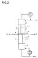
- FIG. 2 shows the separation of a multicomponent mixture Feed mixture 11, 12, 13 in a dividing wall column according to the invention in a low boiler 11, in a medium-boiling valuable product 12 and in one Heavy boiler 13.
- the partition 7, 8 is in its upper and lower part 7 arranged vertically and obliquely in its central part 8.
- the upper Column area 1 is located above the dividing wall 7, 8, and the lower one Column area 6 is arranged below the partition 7, 8.
- the inflow flows into segment f) 9 and the side deduction point is with segment g) 10 connected.
- the dividing wall column used as the test column had a diameter of 0.2 meters, was fitted over a total height of 7 meters with wire mesh packs which had a specific surface area of 500 m 3 / m 2 , and contained a theoretical number of dividing plates of a total of 41 steps.
- the partition was welded between 8th and 30th stages, counted from below.
- the inlet point and the removal point for the liquid side draw were arranged at the same height.
- the liquid was divided into segments b) 2 and d) 3 of the column in a ratio of 1: 3.
- the area ratio of segments b) 2 and d) 3 of the column was 1: 2
- the area ratio of segments c) 4 and e ) 5 of the column was 2: 1.
- the central region 8 of the dividing wall 7, 8 was arranged obliquely and had an angle of 60 ° to the horizontal.
- the head pressure was 5 mbar.
- the feed mixture 11, 12, 13 was fed into the column in liquid form in a flow rate of 8.5 kg / h and at a temperature of approximately 170 °.
- the latter contained 85% p-methoxycinnamic acid ethyl hexyl ester, 5% low-boiling by-products and 10% higher-boiling by-products.
Landscapes
- Chemical & Material Sciences (AREA)
- Chemical Kinetics & Catalysis (AREA)
- Organic Low-Molecular-Weight Compounds And Preparation Thereof (AREA)
- Vaporization, Distillation, Condensation, Sublimation, And Cold Traps (AREA)
- Treatment Of Liquids With Adsorbents In General (AREA)
Applications Claiming Priority (2)
| Application Number | Priority Date | Filing Date | Title |
|---|---|---|---|
| DE10008634A DE10008634A1 (de) | 2000-02-24 | 2000-02-24 | Trennwandkolonne zur Auftrennung eines Vielstoffgemisches |
| DE10008634 | 2000-02-24 |
Publications (3)
| Publication Number | Publication Date |
|---|---|
| EP1127601A2 true EP1127601A2 (fr) | 2001-08-29 |
| EP1127601A3 EP1127601A3 (fr) | 2002-04-24 |
| EP1127601B1 EP1127601B1 (fr) | 2007-06-13 |
Family
ID=7632228
Family Applications (1)
| Application Number | Title | Priority Date | Filing Date |
|---|---|---|---|
| EP01103686A Expired - Lifetime EP1127601B1 (fr) | 2000-02-24 | 2001-02-23 | Colonne de rectification pour la séparation d'un mélange de substances multiples |
Country Status (5)
| Country | Link |
|---|---|
| US (1) | US8092655B2 (fr) |
| EP (1) | EP1127601B1 (fr) |
| AT (1) | ATE364431T1 (fr) |
| DE (2) | DE10008634A1 (fr) |
| ES (1) | ES2286047T3 (fr) |
Cited By (7)
| Publication number | Priority date | Publication date | Assignee | Title |
|---|---|---|---|---|
| EP1321175A3 (fr) * | 2001-12-21 | 2003-12-03 | Basf Aktiengesellschaft | Colonne de distillation à paroi de séparation avec une admission gazeuse totale ou partielle et/ou une soutirage latérale totale ou partielle |
| WO2004009566A1 (fr) * | 2002-07-23 | 2004-01-29 | Basf Aktiengesellschaft | Procede de purification par distillation en continu du methanol, solvant employe pour la synthese d'oxyde de propylene |
| CN102728088A (zh) * | 2011-08-25 | 2012-10-17 | 温州正展机械有限公司 | 外循环减压精馏塔 |
| CN106669214A (zh) * | 2015-11-05 | 2017-05-17 | 中国石油化工股份有限公司大连石油化工研究院 | 一种分壁精馏塔 |
| CN107510953A (zh) * | 2016-11-17 | 2017-12-26 | 洛阳和梦科技有限公司 | 带气液调控器的多段组合型非等分隔板精馏塔 |
| US9873646B2 (en) | 2014-04-22 | 2018-01-23 | Basf Se | Process for preparing cyclohexane from benzene and methylcyclopentane with upstream benzene hydrogenation |
| US10081580B2 (en) | 2012-10-18 | 2018-09-25 | Basf Se | Process for preparing cyclohexane with starting materials originating from a steamcracking process |
Families Citing this family (20)
| Publication number | Priority date | Publication date | Assignee | Title |
|---|---|---|---|---|
| DE10330934A1 (de) * | 2003-07-08 | 2005-02-17 | Basf Ag | Isolierung von Citronellal oder Citronellol aus einem Rohgemisch |
| JP5729766B2 (ja) * | 2009-02-12 | 2015-06-03 | エルジー・ケム・リミテッド | 分離壁型蒸留塔 |
| KR101236664B1 (ko) * | 2009-07-20 | 2013-02-22 | 주식회사 엘지화학 | 에너지 절감형 증류탑 어셈블리 |
| MX338785B (es) * | 2011-01-10 | 2016-05-02 | Koch Glitsch Lp | Bandeja de contacto y metodo para utilizar la misma. |
| KR101372617B1 (ko) * | 2011-11-11 | 2014-03-11 | 주식회사 엘지화학 | 트리할로실란의 정제 장치 |
| EP2778131B1 (fr) * | 2011-11-11 | 2017-10-11 | LG Chem, Ltd. | Dispositif de purification de trihalosilane |
| KR101372791B1 (ko) * | 2011-11-11 | 2014-03-10 | 주식회사 엘지화학 | 트리할로실란의 정제 장치 |
| CN104718179A (zh) | 2012-10-18 | 2015-06-17 | 巴斯夫欧洲公司 | 由甲基环戊烷和苯制备环己烷的新方法 |
| CN104736502B (zh) | 2012-10-18 | 2017-11-10 | 巴斯夫欧洲公司 | 使用源自蒸汽裂化方法的原料制备环己烷的方法 |
| EP2952237A1 (fr) | 2014-06-02 | 2015-12-09 | Sulzer Chemtech AG | Procédé de purification d'acide benzoïque |
| CN105457324B (zh) * | 2014-08-20 | 2019-12-27 | 科思创德国股份有限公司 | 隔板精馏塔 |
| WO2016133876A1 (fr) * | 2015-02-16 | 2016-08-25 | Gtc Technology Us Llc | Configuration de colonne à paroi divisée pour le fractionnement d'une charge de départ dans un procédé de récupération de styrène |
| KR102034179B1 (ko) * | 2017-09-25 | 2019-10-18 | 한화케미칼 주식회사 | 분리벽형 증류탑 및 이를 이용한 염화비닐리덴의 정제 방법 |
| EP3687650A1 (fr) | 2017-09-28 | 2020-08-05 | ExxonMobil Research and Engineering Company | Colonne à paroi de séparation double à produits multiples |
| US11207611B1 (en) | 2018-07-03 | 2021-12-28 | Burns & Mcdonnell Engineering Company, Inc. | Process for separating hydrocarbons in a liquid feed utilizing an externally heated reboiler connected to a divided wall column as the primary source of heat energy |
| US11052324B2 (en) | 2018-09-14 | 2021-07-06 | Exxonmobil Research & Engineering Company | Advanced process control scheme for dividing wall column and dual-dividing wall column with multiple products |
| US11998863B2 (en) | 2019-12-07 | 2024-06-04 | Sulzer Management Ag | Place and cost efficient plant and process for separating one or more purified hydrocarbon streams from crude hydrocarbon streams, such as for naphtha stabilization and LPG recovery |
| CN112933647B (zh) | 2019-12-10 | 2022-07-08 | 中国石油化工股份有限公司 | 气相分配控制装置以及应用该装置的隔板精馏塔 |
| CN113262516B (zh) * | 2021-05-18 | 2022-06-24 | 河南中托力合化学有限公司 | 一种分离c16-c19正构烷烃用隔板塔的侧线采出结构 |
| US11745116B2 (en) * | 2021-10-01 | 2023-09-05 | Manish Bhargava | Apparatus for a dividing wall column in an isomerization unit |
Family Cites Families (11)
| Publication number | Priority date | Publication date | Assignee | Title |
|---|---|---|---|---|
| DE3302525A1 (de) | 1983-01-26 | 1984-07-26 | Basf Ag, 6700 Ludwigshafen | Destillationskolonne zur destillativen zerlegung eines aus mehreren fraktionen bestehenden zulaufproduktes |
| DE3314395A1 (de) | 1983-04-21 | 1984-10-25 | Basf Ag, 6700 Ludwigshafen | Verfahren zur durchfuehrung von chemischen reaktionen und gleichzeitiger destillativer zerlegung eines produktgemisches in mehrere fraktionen mittels einer destillationskolonne |
| DE3327952A1 (de) | 1983-08-03 | 1985-02-14 | Basf Ag, 6700 Ludwigshafen | Verfahren zur destillativen zerlegung eines azeotropen stoffgemisches - analog einer extraktivdestillation - mittels einer destillationskolonne |
| US5669236A (en) * | 1996-08-05 | 1997-09-23 | Praxair Technology, Inc. | Cryogenic rectification system for producing low purity oxygen and high purity oxygen |
| EP0832604A1 (fr) | 1996-09-30 | 1998-04-01 | Koninklijke Philips Electronics N.V. | Méthode et dispositif pour mesurer l'élasticité d'une artère par échographie ultrasonore |
| EP1084741A4 (fr) * | 1998-05-06 | 2003-06-25 | Sumitomo Heavy Industries | Dispositif et procede de distillation |
| DE19959153A1 (de) * | 1999-12-08 | 2001-06-21 | Basf Ag | Verfahren zur Herstellung von Alkalimethylaten |
| DE10100552A1 (de) * | 2001-01-09 | 2002-07-11 | Basf Ag | Verfahren und Vorrichtung zur destillativen Aufarbeitung von 1,6-Hexandiol, 1,5-Pentandiol ung Caprolacton |
| DE10163335A1 (de) * | 2001-12-21 | 2003-07-10 | Basf Ag | Trennwandkolonne mit ganz oder teilweise dampfförmigen Zulauf und/oder ganz oder teilweise dampfförmiger Seitenentnahme |
| US7528290B2 (en) * | 2006-12-28 | 2009-05-05 | Uop Llc | Apparatuses and methods for separating butene-1 from a mixed C4 feed |
| EP2139840A1 (fr) * | 2007-03-23 | 2010-01-06 | Basf Se | Procédé d'obtention d'anhydride maléique par distillation |
-
2000
- 2000-02-24 DE DE10008634A patent/DE10008634A1/de not_active Withdrawn
-
2001
- 2001-02-14 US US09/782,305 patent/US8092655B2/en not_active Expired - Fee Related
- 2001-02-23 DE DE50112613T patent/DE50112613D1/de not_active Expired - Lifetime
- 2001-02-23 AT AT01103686T patent/ATE364431T1/de not_active IP Right Cessation
- 2001-02-23 EP EP01103686A patent/EP1127601B1/fr not_active Expired - Lifetime
- 2001-02-23 ES ES01103686T patent/ES2286047T3/es not_active Expired - Lifetime
Cited By (11)
| Publication number | Priority date | Publication date | Assignee | Title |
|---|---|---|---|---|
| EP1321175A3 (fr) * | 2001-12-21 | 2003-12-03 | Basf Aktiengesellschaft | Colonne de distillation à paroi de séparation avec une admission gazeuse totale ou partielle et/ou une soutirage latérale totale ou partielle |
| US7264696B2 (en) | 2001-12-21 | 2007-09-04 | Basf Aktiengesellschaft | Dividing-wall column with feed in whole or in part in the vaporous state and/or side stream take off in whole or in part in the vaporous state |
| WO2004009566A1 (fr) * | 2002-07-23 | 2004-01-29 | Basf Aktiengesellschaft | Procede de purification par distillation en continu du methanol, solvant employe pour la synthese d'oxyde de propylene |
| US7527712B2 (en) | 2002-07-23 | 2009-05-05 | Basf Aktiengesellschaft | Method for the continuous purification by distillation of the solvent methanol, used in the synthesis of propylene oxide |
| CN102728088A (zh) * | 2011-08-25 | 2012-10-17 | 温州正展机械有限公司 | 外循环减压精馏塔 |
| CN102728088B (zh) * | 2011-08-25 | 2015-11-25 | 温州正展机械有限公司 | 外循环减压精馏塔 |
| US10081580B2 (en) | 2012-10-18 | 2018-09-25 | Basf Se | Process for preparing cyclohexane with starting materials originating from a steamcracking process |
| US9873646B2 (en) | 2014-04-22 | 2018-01-23 | Basf Se | Process for preparing cyclohexane from benzene and methylcyclopentane with upstream benzene hydrogenation |
| CN106669214A (zh) * | 2015-11-05 | 2017-05-17 | 中国石油化工股份有限公司大连石油化工研究院 | 一种分壁精馏塔 |
| CN106669214B (zh) * | 2015-11-05 | 2019-01-08 | 中国石油化工股份有限公司大连石油化工研究院 | 一种分壁精馏塔 |
| CN107510953A (zh) * | 2016-11-17 | 2017-12-26 | 洛阳和梦科技有限公司 | 带气液调控器的多段组合型非等分隔板精馏塔 |
Also Published As
| Publication number | Publication date |
|---|---|
| US8092655B2 (en) | 2012-01-10 |
| DE10008634A1 (de) | 2001-08-30 |
| ES2286047T3 (es) | 2007-12-01 |
| EP1127601A3 (fr) | 2002-04-24 |
| EP1127601B1 (fr) | 2007-06-13 |
| ATE364431T1 (de) | 2007-07-15 |
| DE50112613D1 (de) | 2007-07-26 |
| US20110139604A1 (en) | 2011-06-16 |
Similar Documents
| Publication | Publication Date | Title |
|---|---|---|
| EP1127601B1 (fr) | Colonne de rectification pour la séparation d'un mélange de substances multiples | |
| EP1321175B1 (fr) | Procédé pour la séparation par distillation de mélanges de substances dans une colonne de distillation à paroi de séparation avec une admission gazeuse totale ou partielle et/ou une soutirage latérale totale ou partielle | |
| DE69510000T2 (de) | Strukturierte Packung mit erhöhter Kapazität für Rektifikationssysteme | |
| DE2943687C2 (de) | Trogartige Vorrichtung zum Sammeln und Verteilen der Flüssigkeit für eine Gegenstromkolonne | |
| EP1122213A1 (fr) | Purification de l'ammoniac par distillation | |
| EP0640367B1 (fr) | Colonne de distillation pour la séparation des mélanges de liquides en plusieurs fractions pures | |
| EP1280787B1 (fr) | Procede pour la separation par distillation de melanges contenant du tetrahydrofurane, de la gamma-butyrolactone et/ou du 1,4-butanediol | |
| EP0684060B1 (fr) | Procédé et dispositif de séparation par destillation de mélanges de matières | |
| EP0151693B1 (fr) | Colonne d'échange de matière | |
| EP1040857B1 (fr) | Procédé de séparation par distillation continu d'une substance fondant à haute température | |
| EP1261404B1 (fr) | Procédé pour opérer un distributeur de liquides | |
| DE19617210A1 (de) | Trennwandkolonne zur kontinuierlichen destillativen Zerlegung von Mehrstoffgemischen | |
| EP1455931B1 (fr) | Dispositif et procede de mise en oeuvre de distillations reactives a catalyse heterogene notamment destinees a la fabrication de pseudoionone | |
| WO1993019336A1 (fr) | Procede de separation d'air a basse temperature et installation de separation d'air | |
| EP1166867B1 (fr) | Garnissage pour des colonnes de transfert de chaleur et de masse | |
| DE69833522T2 (de) | Verfahren und Vorrichtung zur Trennung von Stabilisotopen | |
| DE60018639T2 (de) | Verwendung einer strukturierten Packung zur Luftzerlegung | |
| EP0925109B1 (fr) | Chicanes pour colonnes d'echange de substance | |
| WO2017194203A1 (fr) | Dispositif de collecte de liquide, colonne de transfert de matière et procédé de fabrication d'un tel dispositif de collecte de liquide | |
| DE68906191T2 (de) | Kolonnenpackung mit profilierung zum zurueckhalten von fluessigkeit. | |
| EP0264581A1 (fr) | Dispositif de distribution des liquides pour des colonnes de transfert de matière et de chaleur | |
| DE2649414C3 (de) | Stoffaustauschkolonne | |
| EP2062628A1 (fr) | Procédé et dispositif destinés au gain de produits très purs à partir d'une hotte d'aspiration à colonne | |
| EP1534400A1 (fr) | Procede et installation pour realiser une rectification ou une reaction discontinue | |
| DE3004241A1 (de) | Vorrichtung zum abscheiden von fluessigkeitstropfen aus gasen |
Legal Events
| Date | Code | Title | Description |
|---|---|---|---|
| PUAI | Public reference made under article 153(3) epc to a published international application that has entered the european phase |
Free format text: ORIGINAL CODE: 0009012 |
|
| AK | Designated contracting states |
Kind code of ref document: A2 Designated state(s): AT BE CH CY DE DK ES FI FR GB GR IE IT LI LU MC NL PT SE TR |
|
| AX | Request for extension of the european patent |
Free format text: AL;LT;LV;MK;RO;SI |
|
| PUAL | Search report despatched |
Free format text: ORIGINAL CODE: 0009013 |
|
| AK | Designated contracting states |
Kind code of ref document: A3 Designated state(s): AT BE CH CY DE DK ES FI FR GB GR IE IT LI LU MC NL PT SE TR |
|
| AX | Request for extension of the european patent |
Free format text: AL;LT;LV;MK;RO;SI |
|
| 17P | Request for examination filed |
Effective date: 20021022 |
|
| AKX | Designation fees paid |
Free format text: AT BE CH CY DE DK ES FI FR GB GR IE IT LI LU MC NL PT SE TR |
|
| GRAP | Despatch of communication of intention to grant a patent |
Free format text: ORIGINAL CODE: EPIDOSNIGR1 |
|
| GRAS | Grant fee paid |
Free format text: ORIGINAL CODE: EPIDOSNIGR3 |
|
| GRAA | (expected) grant |
Free format text: ORIGINAL CODE: 0009210 |
|
| AK | Designated contracting states |
Kind code of ref document: B1 Designated state(s): AT BE CH CY DE DK ES FI FR GB GR IE IT LI LU MC NL PT SE TR |
|
| REG | Reference to a national code |
Ref country code: GB Ref legal event code: FG4D Free format text: NOT ENGLISH |
|
| REG | Reference to a national code |
Ref country code: CH Ref legal event code: EP |
|
| REG | Reference to a national code |
Ref country code: IE Ref legal event code: FG4D Free format text: LANGUAGE OF EP DOCUMENT: GERMAN |
|
| REF | Corresponds to: |
Ref document number: 50112613 Country of ref document: DE Date of ref document: 20070726 Kind code of ref document: P |
|
| GBT | Gb: translation of ep patent filed (gb section 77(6)(a)/1977) |
Effective date: 20070727 |
|
| PG25 | Lapsed in a contracting state [announced via postgrant information from national office to epo] |
Ref country code: SE Free format text: LAPSE BECAUSE OF FAILURE TO SUBMIT A TRANSLATION OF THE DESCRIPTION OR TO PAY THE FEE WITHIN THE PRESCRIBED TIME-LIMIT Effective date: 20070913 |
|
| ET | Fr: translation filed | ||
| REG | Reference to a national code |
Ref country code: ES Ref legal event code: FG2A Ref document number: 2286047 Country of ref document: ES Kind code of ref document: T3 |
|
| REG | Reference to a national code |
Ref country code: IE Ref legal event code: FD4D |
|
| PG25 | Lapsed in a contracting state [announced via postgrant information from national office to epo] |
Ref country code: PT Free format text: LAPSE BECAUSE OF FAILURE TO SUBMIT A TRANSLATION OF THE DESCRIPTION OR TO PAY THE FEE WITHIN THE PRESCRIBED TIME-LIMIT Effective date: 20071113 Ref country code: IE Free format text: LAPSE BECAUSE OF FAILURE TO SUBMIT A TRANSLATION OF THE DESCRIPTION OR TO PAY THE FEE WITHIN THE PRESCRIBED TIME-LIMIT Effective date: 20070613 |
|
| RAP2 | Party data changed (patent owner data changed or rights of a patent transferred) |
Owner name: BASF SE |
|
| PLBE | No opposition filed within time limit |
Free format text: ORIGINAL CODE: 0009261 |
|
| STAA | Information on the status of an ep patent application or granted ep patent |
Free format text: STATUS: NO OPPOSITION FILED WITHIN TIME LIMIT |
|
| PG25 | Lapsed in a contracting state [announced via postgrant information from national office to epo] |
Ref country code: GR Free format text: LAPSE BECAUSE OF FAILURE TO SUBMIT A TRANSLATION OF THE DESCRIPTION OR TO PAY THE FEE WITHIN THE PRESCRIBED TIME-LIMIT Effective date: 20070914 Ref country code: DK Free format text: LAPSE BECAUSE OF FAILURE TO SUBMIT A TRANSLATION OF THE DESCRIPTION OR TO PAY THE FEE WITHIN THE PRESCRIBED TIME-LIMIT Effective date: 20070613 |
|
| NLT2 | Nl: modifications (of names), taken from the european patent patent bulletin |
Owner name: BASF SE Effective date: 20080305 |
|
| 26N | No opposition filed |
Effective date: 20080314 |
|
| PG25 | Lapsed in a contracting state [announced via postgrant information from national office to epo] |
Ref country code: MC Free format text: LAPSE BECAUSE OF NON-PAYMENT OF DUE FEES Effective date: 20080228 |
|
| PG25 | Lapsed in a contracting state [announced via postgrant information from national office to epo] |
Ref country code: FI Free format text: LAPSE BECAUSE OF FAILURE TO SUBMIT A TRANSLATION OF THE DESCRIPTION OR TO PAY THE FEE WITHIN THE PRESCRIBED TIME-LIMIT Effective date: 20070613 |
|
| PG25 | Lapsed in a contracting state [announced via postgrant information from national office to epo] |
Ref country code: AT Free format text: LAPSE BECAUSE OF NON-PAYMENT OF DUE FEES Effective date: 20080223 |
|
| PG25 | Lapsed in a contracting state [announced via postgrant information from national office to epo] |
Ref country code: CY Free format text: LAPSE BECAUSE OF FAILURE TO SUBMIT A TRANSLATION OF THE DESCRIPTION OR TO PAY THE FEE WITHIN THE PRESCRIBED TIME-LIMIT Effective date: 20070613 |
|
| PG25 | Lapsed in a contracting state [announced via postgrant information from national office to epo] |
Ref country code: LU Free format text: LAPSE BECAUSE OF NON-PAYMENT OF DUE FEES Effective date: 20080223 |
|
| PGFP | Annual fee paid to national office [announced via postgrant information from national office to epo] |
Ref country code: TR Payment date: 20100129 Year of fee payment: 10 |
|
| PG25 | Lapsed in a contracting state [announced via postgrant information from national office to epo] |
Ref country code: TR Free format text: LAPSE BECAUSE OF NON-PAYMENT OF DUE FEES Effective date: 20110223 |
|
| REG | Reference to a national code |
Ref country code: FR Ref legal event code: PLFP Year of fee payment: 16 |
|
| REG | Reference to a national code |
Ref country code: FR Ref legal event code: PLFP Year of fee payment: 17 |
|
| REG | Reference to a national code |
Ref country code: FR Ref legal event code: PLFP Year of fee payment: 18 |
|
| PGFP | Annual fee paid to national office [announced via postgrant information from national office to epo] |
Ref country code: IT Payment date: 20200224 Year of fee payment: 20 Ref country code: ES Payment date: 20200323 Year of fee payment: 20 Ref country code: NL Payment date: 20200225 Year of fee payment: 20 Ref country code: GB Payment date: 20200226 Year of fee payment: 20 |
|
| PGFP | Annual fee paid to national office [announced via postgrant information from national office to epo] |
Ref country code: CH Payment date: 20200225 Year of fee payment: 20 Ref country code: BE Payment date: 20200225 Year of fee payment: 20 |
|
| PGFP | Annual fee paid to national office [announced via postgrant information from national office to epo] |
Ref country code: FR Payment date: 20200225 Year of fee payment: 20 |
|
| PGFP | Annual fee paid to national office [announced via postgrant information from national office to epo] |
Ref country code: DE Payment date: 20200429 Year of fee payment: 20 |
|
| REG | Reference to a national code |
Ref country code: DE Ref legal event code: R071 Ref document number: 50112613 Country of ref document: DE |
|
| REG | Reference to a national code |
Ref country code: NL Ref legal event code: MK Effective date: 20210222 |
|
| REG | Reference to a national code |
Ref country code: CH Ref legal event code: PL |
|
| REG | Reference to a national code |
Ref country code: GB Ref legal event code: PE20 Expiry date: 20210222 |
|
| REG | Reference to a national code |
Ref country code: BE Ref legal event code: MK Effective date: 20210223 |
|
| PG25 | Lapsed in a contracting state [announced via postgrant information from national office to epo] |
Ref country code: GB Free format text: LAPSE BECAUSE OF EXPIRATION OF PROTECTION Effective date: 20210222 |
|
| REG | Reference to a national code |
Ref country code: ES Ref legal event code: FD2A Effective date: 20210729 |
|
| PG25 | Lapsed in a contracting state [announced via postgrant information from national office to epo] |
Ref country code: ES Free format text: LAPSE BECAUSE OF EXPIRATION OF PROTECTION Effective date: 20210224 |