EP1127620A1 - Broyeur à impact - Google Patents
Broyeur à impact Download PDFInfo
- Publication number
- EP1127620A1 EP1127620A1 EP01100927A EP01100927A EP1127620A1 EP 1127620 A1 EP1127620 A1 EP 1127620A1 EP 01100927 A EP01100927 A EP 01100927A EP 01100927 A EP01100927 A EP 01100927A EP 1127620 A1 EP1127620 A1 EP 1127620A1
- Authority
- EP
- European Patent Office
- Prior art keywords
- swingles
- impact crusher
- rotor
- rotation
- recesses
- Prior art date
- Legal status (The legal status is an assumption and is not a legal conclusion. Google has not performed a legal analysis and makes no representation as to the accuracy of the status listed.)
- Withdrawn
Links
- 239000000463 material Substances 0.000 claims abstract description 42
- 239000000945 filler Substances 0.000 claims abstract description 12
- 230000002093 peripheral effect Effects 0.000 claims description 3
- 229920002994 synthetic fiber Polymers 0.000 claims description 2
- 229910000831 Steel Inorganic materials 0.000 claims 1
- 230000003014 reinforcing effect Effects 0.000 claims 1
- 239000010959 steel Substances 0.000 claims 1
- 230000009471 action Effects 0.000 abstract description 4
- 238000003801 milling Methods 0.000 abstract 1
- 238000005259 measurement Methods 0.000 description 23
- 238000004364 calculation method Methods 0.000 description 21
- 230000005611 electricity Effects 0.000 description 11
- 241000196324 Embryophyta Species 0.000 description 10
- 238000012360 testing method Methods 0.000 description 9
- 239000000203 mixture Substances 0.000 description 8
- 239000002245 particle Substances 0.000 description 8
- 241000209219 Hordeum Species 0.000 description 7
- 235000007340 Hordeum vulgare Nutrition 0.000 description 7
- 238000010276 construction Methods 0.000 description 5
- 238000012545 processing Methods 0.000 description 5
- 241001465754 Metazoa Species 0.000 description 4
- 230000008901 benefit Effects 0.000 description 4
- 239000000428 dust Substances 0.000 description 4
- 238000005265 energy consumption Methods 0.000 description 4
- 235000019197 fats Nutrition 0.000 description 4
- 229910052500 inorganic mineral Inorganic materials 0.000 description 4
- 230000014759 maintenance of location Effects 0.000 description 4
- 235000010755 mineral Nutrition 0.000 description 4
- 239000011707 mineral Substances 0.000 description 4
- 235000013379 molasses Nutrition 0.000 description 4
- 239000008188 pellet Substances 0.000 description 4
- 235000013343 vitamin Nutrition 0.000 description 4
- 229940088594 vitamin Drugs 0.000 description 4
- 229930003231 vitamin Natural products 0.000 description 4
- 239000011782 vitamin Substances 0.000 description 4
- 241000209140 Triticum Species 0.000 description 3
- 235000021307 Triticum Nutrition 0.000 description 3
- 238000004519 manufacturing process Methods 0.000 description 3
- 229920006395 saturated elastomer Polymers 0.000 description 3
- 238000005029 sieve analysis Methods 0.000 description 3
- 235000019733 Fish meal Nutrition 0.000 description 2
- 240000008042 Zea mays Species 0.000 description 2
- 235000005824 Zea mays ssp. parviglumis Nutrition 0.000 description 2
- 235000002017 Zea mays subsp mays Nutrition 0.000 description 2
- 235000005822 corn Nutrition 0.000 description 2
- 238000009826 distribution Methods 0.000 description 2
- 239000004467 fishmeal Substances 0.000 description 2
- 235000012054 meals Nutrition 0.000 description 2
- 238000000034 method Methods 0.000 description 2
- 238000005453 pelletization Methods 0.000 description 2
- 230000035515 penetration Effects 0.000 description 2
- 239000002994 raw material Substances 0.000 description 2
- XLYOFNOQVPJJNP-UHFFFAOYSA-N water Substances O XLYOFNOQVPJJNP-UHFFFAOYSA-N 0.000 description 2
- 235000015099 wheat brans Nutrition 0.000 description 2
- 241000251468 Actinopterygii Species 0.000 description 1
- 244000075850 Avena orientalis Species 0.000 description 1
- 235000007319 Avena orientalis Nutrition 0.000 description 1
- 235000016068 Berberis vulgaris Nutrition 0.000 description 1
- 241000335053 Beta vulgaris Species 0.000 description 1
- GXCLVBGFBYZDAG-UHFFFAOYSA-N N-[2-(1H-indol-3-yl)ethyl]-N-methylprop-2-en-1-amine Chemical compound CN(CCC1=CNC2=C1C=CC=C2)CC=C GXCLVBGFBYZDAG-UHFFFAOYSA-N 0.000 description 1
- 238000012356 Product development Methods 0.000 description 1
- 241000282887 Suidae Species 0.000 description 1
- 238000010521 absorption reaction Methods 0.000 description 1
- 230000001133 acceleration Effects 0.000 description 1
- 238000004458 analytical method Methods 0.000 description 1
- 230000015572 biosynthetic process Effects 0.000 description 1
- 238000013461 design Methods 0.000 description 1
- 230000001627 detrimental effect Effects 0.000 description 1
- 235000021588 free fatty acids Nutrition 0.000 description 1
- 238000010438 heat treatment Methods 0.000 description 1
- 230000006872 improvement Effects 0.000 description 1
- 238000009776 industrial production Methods 0.000 description 1
- 235000015816 nutrient absorption Nutrition 0.000 description 1
- 235000015097 nutrients Nutrition 0.000 description 1
- 235000016709 nutrition Nutrition 0.000 description 1
- 230000003647 oxidation Effects 0.000 description 1
- 238000007254 oxidation reaction Methods 0.000 description 1
- 230000000149 penetrating effect Effects 0.000 description 1
- 238000003825 pressing Methods 0.000 description 1
- 230000008569 process Effects 0.000 description 1
- 238000009423 ventilation Methods 0.000 description 1
- 238000005303 weighing Methods 0.000 description 1
- 239000013585 weight reducing agent Substances 0.000 description 1
Images



Classifications
-
- B—PERFORMING OPERATIONS; TRANSPORTING
- B02—CRUSHING, PULVERISING, OR DISINTEGRATING; PREPARATORY TREATMENT OF GRAIN FOR MILLING
- B02C—CRUSHING, PULVERISING, OR DISINTEGRATING IN GENERAL; MILLING GRAIN
- B02C13/00—Disintegrating by mills having rotary beater elements ; Hammer mills
- B02C13/26—Details
- B02C13/28—Shape or construction of beater elements
-
- B—PERFORMING OPERATIONS; TRANSPORTING
- B02—CRUSHING, PULVERISING, OR DISINTEGRATING; PREPARATORY TREATMENT OF GRAIN FOR MILLING
- B02C—CRUSHING, PULVERISING, OR DISINTEGRATING IN GENERAL; MILLING GRAIN
- B02C13/00—Disintegrating by mills having rotary beater elements ; Hammer mills
- B02C13/26—Details
- B02C13/28—Shape or construction of beater elements
- B02C2013/2808—Shape or construction of beater elements the beater elements are attached to disks mounted on a shaft
Definitions
- the present invention concerns an impact crusher with a rotor provided with several rows of swingles along its length, the swingles extending perpendicularly to the rotational axis of the crusher, and the rotor being disposed inside a largely cylindrical screen having an elongate opening for inserting material and through which processed material leaves the crusher, where the rotor comprises a closed drum in the space within the swingles with recesses in its surface for accommodating the suspended ends of the swingles, while the active ends of the swingles extends outside the surface of the drum.
- the invention furthermore concerns a rotor for such an impact crusher.
- Impact crushers or hammer mills have been known for many years for grinding different materials including corn. Thus they have been widely used in combination with transport blowers and/or suction ventilators that contribute to convey processed material out through the screen and possibly further via transport pipelines. Alternatively, further transport of processed material occurs by means of screw conveyors or conveyor belts disposed under an after container or so-called dome wherefrom dust-containing air is tapped from the top and discharged to the outside via a filter.
- the impact crusher has thus been used for industrial production of feedstuffs by grinding corn and admixing additional materials.
- the processed and mixed product is usually conveyed further on to a pelletizing machine for making the feed in pellet form. It is by such an application that the present invention has appeared. However, the invention yields further advantages by application in other areas, as for example the crushing of ore.
- the Danish feed production is 5,700,000 tons per year. It is estimated that almost all the production is ground in impact crushers. The grinding is an energy intensive process, and it is thus estimated that about 55,290,000 kWh are used annually which by the present electricity cost of DKK 0,45 per kWh corresponds to a total energy cost of DKK 24,880,500 per year.
- the impact crusher is one of the most energy consuming production machines. Depending on the degree of fineness, the energy consumption of the impact crusher may constitute up to 30% of the total energy consumption of the feedstuff plant.
- the traditional rotor in an impact crusher is built up by a row of swingles extending in parallel with the axis of rotation, or which extend helically around the circumference of the rotor.
- the swingles are fastened pivotably to the drum which is built up from drum plates disposed at mutual distance, allowing fitting of the swingles between two succeeding plates.
- Material introduced in the impact crusher has a tendency to be passed into the interspace between two plates during the processing. Due to the rotation of the rotor, this material may have long retention time in the impact crusher and be processed several times by the swingles. Hereby the material, or a part of the material, can be crushed to unnecessarily and/or undesirably small particle sizes. For example, well-defined particle sizes for animal feed are required for efficient absorption of nutrients from the feed.
- the material has a tendency of falling through the rotor toward the bottom of the impact crusher and leave the processing chamber via a relatively small part of the periphery at the bottom of the chamber.
- a large amount of the materials are sucked out through the screen due to the action of transport ventilators or suction ventilators. This causes that the processing chamber of the impact crusher cannot be utilised fully and thereby an optimal economy is not achieved.
- the rotor according to the invention is peculiar in that it comprises a closed drum in the space within the swingles with recesses in its surface for accommodating the suspended end of the swingles, while the active ends of the swingles extend outside the surface of the drum.
- the new rotor is furthermore constructed so that the ventilation loss becomes the least possible which is also contributing to reducing the air demand.
- the decisive advantage of the new impact crusher is thus the possibility of grinding a uniform product with a saving in the energy consumption. As it appears from the performed tests and measurements, these advantages are achieved.
- the side wall of the recesses will have different rotation depending on the rotational speed and the intended use of the impact crusher. With less diameter and greater rotational speed used by making animal feed it is preferred to have side walls extending largely radially. By impact crushers with large diameter and less rotational speed it is preferred that the side walls of the recesses are designed as indicated in claim 5. This has appeared to yield the best efficiency of the mill.
- the filling surfaces of the drum are formed by synthetic material as indicated in claim 3.
- the rotor will preferably be hollow.
- the inlet opening will be situated in an upward facing part of the screen surrounding the grinding chamber.
- outlet openings may be formed around the remaining part of the circumference of the screen as the surface, where the material is thrown against the screen, will be conveyed round along the circumference of the screen as the recesses are rotated, and thereby the ejection of the material by the side walls will constantly circulate inside the grinding chamber.
- the rotor will preferably be made in such a way that the suspended ends of the swingles are situated within the circumference covered by the closed drum, whereas the active ends of the swingles will extend outside the surface of the drum.
- the active end of the swingles will extend out in an area where the material is forced to be in a cylindrical shell at the inner side of the screen. This will prevent the material from penetrating in behind the recesses at the inner of the drum and hereby reduce the risk of an increased retention time of the material in the impact crusher.
- Fig. 1 shows an impact crusher 1 according to the invention built up over a dome 2 where air and material pass down onto the underside of the impact crusher. Material is removed via a conveyor 3 and dust saturated air 4 is conducted via a nozzle filter 5 to the outside via transport blower 6.7 indicates an air intake at the top of the impact crusher, and 8 indicates a conveyor for introducing material at an opening in the top of the impact crusher.
- Fig. 1 is illustrated a view from above of the plant. From this appears that the impact crusher is oriented with a motor 9 driving the rotor which is oriented perpendicularly to the direction of flow of the dust saturated air 4 in the dome. This influences the properties of the efficiency of the plant.
- the plant with the impact crusher 1 according to the invention located as illustrated in Fig. 2.
- the impact crusher is placed with the rotor extending in parallel with the flow direction of the dust saturated air 4.
- the direction of rotation of the impact crusher does not have any influence on the efficiency of the plant.
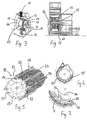
- Fig. 3 illustrates a prior art impact crusher with an inlet opening at the top of a screen 11 where processed material 12 passes through.
- the rotor comprises swingles 13 that are pivotably suspended about a journal 14 fastened on support plates 15 which constitute the rotor of the impact crusher.
- the rotor rotates about a central journal 16.
- Fig. 4 which illustrates a partly sectional view, there will be interspaces between succeeding support plates 15 into which the material may fall when led via the opening 10.
- the material is preferably introduced batch-wise but may also be introduced continually.
- a rotor 18 for an impact crusher according to the invention.
- the swingles 13 are pivotably suspended on support plates 15 by a pin 14. Swingles 13 are disposed on rows 19 in parallel with the shaft 20 for the rotor 18. Around the circumference is disposed four swingles 13 in each plane.
- the recess 22 has an extension so that a swingle may freely pivot inside the formed recess.
- the fillers 21 thus closes the central part of the drum except within the area where the swingles are.
- the recesses 22 may have less dimension that shown in Fig. 5 so that the size of the recesses largely corresponds to only accommodating the suspended ends 23 of the swingles 13 so that all of the active ends 24 of the swingles are largely outside the circumferential surface formed by the plates of the drum. With this construction, material can only be in the area outside the drum and within the screen, i.e. in active working area of the swingles 13 as indicated by 25 in Figs. 6 and 7.
- the rotor will rotate in the direction of rotation 26, and the material will be thrown against the inner side of the drum 11 and be thrown out when having a size which is less than the apertures of the screen.
- Fig. 3 is illustrated how material passes at one side and partly through the inner of the drum for only leaving the impact crusher through the bottom.
- Fig. 6 is illustrated how the material is distributed over a substantial part of the circumference and has the possibility of leaving the grinding chamber and a large part of the circumference of the screen.
- the penetration of the material through the screen is assisted by its being flung out according to the tangential line 28 illustrated in Fig. 8.
- the tangential lines are largely perpendicular to side walls 29 in the recesses 22, the side walls 29 being located forward as seen in the direction 26 of rotation of the rotor. It may be said that opposite to each of the tangential ejection lines 28, an area corresponding to a so-called acceleration zone 30 from a traditional impact crusher occurs, as indicated in Fig. 9. Thus there will be a greater circumference which is utilised, and simultaneously the mechanical energy occurring by the action of the side walls 29 on the particles will contribute to increasing the efficiency of the penetration of the material.
- the support plates are made with four wings 31 between each of the cavities 22. These wings are preferably made with cavities 32. Also the central part 33 of the fillers will be provided with cavities 34 for reasons of saving weight.
- Figs. 10 and 11 show the wings 31 formed with a curvature where at least the side wall 29 facing against the direction of rotation 26 has a lower part 35 at the bottom 36 of the recess curving in direction along the direction of rotation, and that the outer part 37 of the side wall has a curvature curving in direction against the direction 26 of rotation.
- This embodiment has, however, appeared particularly advantageous in connection with impact crushers used for making animal feed for pigs with particle sizes that have to be in the magnitude 1 mm or larger for reasons of nutrient absorption in the animals.
- the rotational speed will be 1500 rpm and the diameter be about 850 mm, whereby a peripheral speed of about 82 m/s is achieved.
- the alternative embodiment on filler 21 shown in Fig. 11 is a corresponding side wall 29, which is oriented largely radially, and is approximately straight except a curvature at the outer end 37 of the side wall 29.
- This embodiment belongs particularly to impact crushers used in making fish feed and pet feed where a very fine grinding of the product is to be established, for example with particle sizes down to under 850 micrometer.
- Such a crusher motor will have a rotational speed in the magnitude 2900 rpm and a diameter of about 400 mm. This will result in a peripheral speed of about 92 m/s.
- the shown embodiment has appeared to be suitable for such application of the impact crusher.
- the impact crusher has been explained in the above. However, it will be possible to design this or the rotor of the impact crusher in other ways than specifically illustrated. Thus it will be possible to make the rotor as a closed cylindrical body with recesses provided for placing the swingles 13 as alternative to the recesses established by using fillers between the support plates. Only it is important that the rotor will appear as a closed unit which prevents material from flowing within the area that can be processed by the swingles.
- FIG. 1 Schematic draft of the machine plant is shown in Fig. 1.
- the impact crusher was mounted with a diameter 3 mm densely perforated screen.
- the impact crusher was driven by an electric motor with 315 kW power, voltage of 400 V, current of 545 A, cos. j of 0,87 and rotational speed of 1485 rpm.
- the suction blower was also powered by an electric motor yielding 22 kW, voltage of 400 V, current of 41 A, cos. j of 0,86 and rotational speed of 1470 rpm.
- the hopper of the impact crusher was filled with the described mixture of raw materials before the grinding was initiated. During the measurements, the following was registered:
- Charge size was determined by means of the weighing out scales under the raw material silos.
- Measurement 1 impact crusher with traditional rotor
- a pig mixture was ground, consisting of: 975 kg Danish spring barley 39 % 475 kg soy meal 19 % 125 kg wheat bran 5 % 125 kg oats 5 % 50 kg beet pellets 2 % 25 kg fish meal 1 % 1775 kg mixture 71 % 475 kg wheat 19 % 250 kg fat, molasse, vitamins and minerals 10 % 2500 kg charge size 100 % Note: 19 % wheat (475 kg) were supplied to the roller mill and the rest, i.e. 250 kg fat, molasse, vitamins and minerals, were supplied directly to hopper and mixer.
- an estimated net energy saving of 23 - 28 % may be expected in using the impact crusher according to the invention.
Landscapes
- Engineering & Computer Science (AREA)
- Food Science & Technology (AREA)
- Crushing And Pulverization Processes (AREA)
Applications Claiming Priority (2)
| Application Number | Priority Date | Filing Date | Title |
|---|---|---|---|
| DK200000070A DK200000070A (da) | 2000-01-17 | 2000-01-17 | Slaglemølle |
| DK200000070 | 2000-01-17 |
Publications (1)
| Publication Number | Publication Date |
|---|---|
| EP1127620A1 true EP1127620A1 (fr) | 2001-08-29 |
Family
ID=8158954
Family Applications (1)
| Application Number | Title | Priority Date | Filing Date |
|---|---|---|---|
| EP01100927A Withdrawn EP1127620A1 (fr) | 2000-01-17 | 2001-01-17 | Broyeur à impact |
Country Status (2)
| Country | Link |
|---|---|
| EP (1) | EP1127620A1 (fr) |
| DK (1) | DK200000070A (fr) |
Cited By (5)
| Publication number | Priority date | Publication date | Assignee | Title |
|---|---|---|---|---|
| WO2002057018A1 (fr) * | 2001-01-16 | 2002-07-25 | Sprout-Matador A/S | Rotor pour broyeur-concasseur |
| CN102513188A (zh) * | 2011-12-20 | 2012-06-27 | 扬州中欧工业机器人有限公司 | 一种锤片式粉碎机转子及使用该转子的粉碎机 |
| CN106076496A (zh) * | 2016-07-26 | 2016-11-09 | 广西南美环保科技有限公司 | 一种淀粉粉碎机 |
| CN109331955A (zh) * | 2018-11-20 | 2019-02-15 | 台州市硕阳机械股份有限公司 | 一种粉碎机 |
| US20220193687A1 (en) * | 2020-12-22 | 2022-06-23 | Troyer Brothers, Inc. | Apparatus for Pulverizing Compressed Thermal Insulation |
Citations (5)
| Publication number | Priority date | Publication date | Assignee | Title |
|---|---|---|---|---|
| GB1569376A (en) * | 1976-05-19 | 1980-06-11 | Lindemann Maschfab Gmbh | Rotary hammer breakers |
| DE2943456A1 (de) * | 1979-10-27 | 1982-02-18 | Maschinenfabrik B. Maier Kg, 4800 Bielefeld | Vorrichtung zum zerkleinern , insbesondere von rinden und einjahrespflanzen |
| FR2523872A1 (fr) * | 1982-03-23 | 1983-09-30 | Mach Applic Environnement | Rotor pour broyeur a marteaux |
| FR2544628A1 (fr) * | 1983-04-20 | 1984-10-26 | Neles Oy | Broyeur a marteaux |
| EP0873791A2 (fr) * | 1997-04-24 | 1998-10-28 | Svedala Industries, Inc. | Rotor pour déchiqueteurs et broyeurs à marteaux |
-
2000
- 2000-01-17 DK DK200000070A patent/DK200000070A/da not_active Application Discontinuation
-
2001
- 2001-01-17 EP EP01100927A patent/EP1127620A1/fr not_active Withdrawn
Patent Citations (5)
| Publication number | Priority date | Publication date | Assignee | Title |
|---|---|---|---|---|
| GB1569376A (en) * | 1976-05-19 | 1980-06-11 | Lindemann Maschfab Gmbh | Rotary hammer breakers |
| DE2943456A1 (de) * | 1979-10-27 | 1982-02-18 | Maschinenfabrik B. Maier Kg, 4800 Bielefeld | Vorrichtung zum zerkleinern , insbesondere von rinden und einjahrespflanzen |
| FR2523872A1 (fr) * | 1982-03-23 | 1983-09-30 | Mach Applic Environnement | Rotor pour broyeur a marteaux |
| FR2544628A1 (fr) * | 1983-04-20 | 1984-10-26 | Neles Oy | Broyeur a marteaux |
| EP0873791A2 (fr) * | 1997-04-24 | 1998-10-28 | Svedala Industries, Inc. | Rotor pour déchiqueteurs et broyeurs à marteaux |
Cited By (8)
| Publication number | Priority date | Publication date | Assignee | Title |
|---|---|---|---|---|
| WO2002057018A1 (fr) * | 2001-01-16 | 2002-07-25 | Sprout-Matador A/S | Rotor pour broyeur-concasseur |
| US7040560B2 (en) | 2001-01-16 | 2006-05-09 | Sprout-Matador A/S | Rotor for hammer-or chopper mill |
| CN102513188A (zh) * | 2011-12-20 | 2012-06-27 | 扬州中欧工业机器人有限公司 | 一种锤片式粉碎机转子及使用该转子的粉碎机 |
| CN106076496A (zh) * | 2016-07-26 | 2016-11-09 | 广西南美环保科技有限公司 | 一种淀粉粉碎机 |
| CN106076496B (zh) * | 2016-07-26 | 2018-12-14 | 广西南美环保科技有限公司 | 一种淀粉粉碎机 |
| CN109331955A (zh) * | 2018-11-20 | 2019-02-15 | 台州市硕阳机械股份有限公司 | 一种粉碎机 |
| CN109331955B (zh) * | 2018-11-20 | 2020-11-17 | 浙江硕阳机械股份有限公司 | 一种粉碎机 |
| US20220193687A1 (en) * | 2020-12-22 | 2022-06-23 | Troyer Brothers, Inc. | Apparatus for Pulverizing Compressed Thermal Insulation |
Also Published As
| Publication number | Publication date |
|---|---|
| DK200000070A (da) | 2001-07-18 |
Similar Documents
| Publication | Publication Date | Title |
|---|---|---|
| EP0529843B1 (fr) | Méthode et système pour le broyage de la farine | |
| CA2314634C (fr) | Sechoir a action instantanee | |
| AU615073B2 (en) | System for flouring wheat | |
| EP1195201B1 (fr) | Broyeur méchanique | |
| CN106040405A (zh) | 内置选粉机的预粉立磨联合半终粉磨系统 | |
| CN113649131B (zh) | 一种自动化饲料粉碎混合装置 | |
| EP1127620A1 (fr) | Broyeur à impact | |
| CN208321045U (zh) | 一种新型饲料粉碎机 | |
| CN101652191A (zh) | 用于筛选给料的装置及方法 | |
| JP3173062B2 (ja) | 分級装置及び該分級装置を備えた粉砕設備 | |
| CN207951671U (zh) | 新型饲料粉碎机 | |
| CN108895480A (zh) | 水平定量送料机构及热风炉 | |
| US5145117A (en) | Process of and system for flouring wheat | |
| CN116673084A (zh) | 一种沸腾式循环磨粉机 | |
| JPH03187957A (ja) | 予備粉砕装置を備えたセメント製造装置 | |
| CN201493133U (zh) | 锤片粉碎机 | |
| CN115555093A (zh) | 一种禽畜饲料粉碎装置 | |
| KR102352635B1 (ko) | 고형소재를 위한 분쇄장치 | |
| CN201320792Y (zh) | 树皮粉碎机 | |
| CN108525606A (zh) | 一种具有细粉回收功能的饲料制粒打磨装置 | |
| CN215963965U (zh) | 一种卧式干燥研磨一体粉碎机 | |
| DK200100108U3 (da) | Slaglemølle, samt rotor til slaglemølle | |
| CN209999529U (zh) | 一种可塑性塑料粉粹装置 | |
| CN2186603Y (zh) | 可随意调控成品粒度的粉碎机 | |
| CN216605550U (zh) | 一种粉磨闭路回粉系统 |
Legal Events
| Date | Code | Title | Description |
|---|---|---|---|
| PUAI | Public reference made under article 153(3) epc to a published international application that has entered the european phase |
Free format text: ORIGINAL CODE: 0009012 |
|
| AK | Designated contracting states |
Kind code of ref document: A1 Designated state(s): AT BE CH CY DE DK ES FI FR GB GR IE IT LI LU MC NL PT SE TR |
|
| AX | Request for extension of the european patent |
Free format text: AL;LT;LV;MK;RO;SI |
|
| AKX | Designation fees paid | ||
| REG | Reference to a national code |
Ref country code: DE Ref legal event code: 8566 |
|
| STAA | Information on the status of an ep patent application or granted ep patent |
Free format text: STATUS: THE APPLICATION IS DEEMED TO BE WITHDRAWN |
|
| 18D | Application deemed to be withdrawn |
Effective date: 20020430 |