EP1127640B1 - Plaquette à tronçonner ou de rainurage, fixée par frottement - Google Patents
Plaquette à tronçonner ou de rainurage, fixée par frottement Download PDFInfo
- Publication number
- EP1127640B1 EP1127640B1 EP01104241A EP01104241A EP1127640B1 EP 1127640 B1 EP1127640 B1 EP 1127640B1 EP 01104241 A EP01104241 A EP 01104241A EP 01104241 A EP01104241 A EP 01104241A EP 1127640 B1 EP1127640 B1 EP 1127640B1
- Authority
- EP
- European Patent Office
- Prior art keywords
- insert
- holder
- recess
- recessed portions
- walls
- Prior art date
- Legal status (The legal status is an assumption and is not a legal conclusion. Google has not performed a legal analysis and makes no representation as to the accuracy of the status listed.)
- Expired - Lifetime
Links
- 238000005520 cutting process Methods 0.000 claims description 7
- 238000003780 insertion Methods 0.000 description 2
- 230000037431 insertion Effects 0.000 description 2
- 229910052751 metal Inorganic materials 0.000 description 2
- 239000002184 metal Substances 0.000 description 2
- UONOETXJSWQNOL-UHFFFAOYSA-N tungsten carbide Chemical compound [W+]#[C-] UONOETXJSWQNOL-UHFFFAOYSA-N 0.000 description 2
- 238000007792 addition Methods 0.000 description 1
- 238000012217 deletion Methods 0.000 description 1
- 230000037430 deletion Effects 0.000 description 1
- 238000003754 machining Methods 0.000 description 1
- 238000012986 modification Methods 0.000 description 1
- 230000004048 modification Effects 0.000 description 1
- 238000006467 substitution reaction Methods 0.000 description 1
Images


Classifications
-
- B—PERFORMING OPERATIONS; TRANSPORTING
- B23—MACHINE TOOLS; METAL-WORKING NOT OTHERWISE PROVIDED FOR
- B23B—TURNING; BORING
- B23B27/00—Tools for turning or boring machines; Tools of a similar kind in general; Accessories therefor
- B23B27/04—Cutting-off tools
-
- B—PERFORMING OPERATIONS; TRANSPORTING
- B23—MACHINE TOOLS; METAL-WORKING NOT OTHERWISE PROVIDED FOR
- B23B—TURNING; BORING
- B23B2205/00—Fixation of cutting inserts in holders
- B23B2205/02—Fixation using an elastically deformable clamping member
-
- Y—GENERAL TAGGING OF NEW TECHNOLOGICAL DEVELOPMENTS; GENERAL TAGGING OF CROSS-SECTIONAL TECHNOLOGIES SPANNING OVER SEVERAL SECTIONS OF THE IPC; TECHNICAL SUBJECTS COVERED BY FORMER USPC CROSS-REFERENCE ART COLLECTIONS [XRACs] AND DIGESTS
- Y10—TECHNICAL SUBJECTS COVERED BY FORMER USPC
- Y10T—TECHNICAL SUBJECTS COVERED BY FORMER US CLASSIFICATION
- Y10T407/00—Cutters, for shaping
- Y10T407/22—Cutters, for shaping including holder having seat for inserted tool
- Y10T407/2272—Cutters, for shaping including holder having seat for inserted tool with separate means to fasten tool to holder
- Y10T407/2282—Cutters, for shaping including holder having seat for inserted tool with separate means to fasten tool to holder including tool holding clamp and clamp actuator
-
- Y—GENERAL TAGGING OF NEW TECHNOLOGICAL DEVELOPMENTS; GENERAL TAGGING OF CROSS-SECTIONAL TECHNOLOGIES SPANNING OVER SEVERAL SECTIONS OF THE IPC; TECHNICAL SUBJECTS COVERED BY FORMER USPC CROSS-REFERENCE ART COLLECTIONS [XRACs] AND DIGESTS
- Y10—TECHNICAL SUBJECTS COVERED BY FORMER USPC
- Y10T—TECHNICAL SUBJECTS COVERED BY FORMER US CLASSIFICATION
- Y10T407/00—Cutters, for shaping
- Y10T407/22—Cutters, for shaping including holder having seat for inserted tool
- Y10T407/2272—Cutters, for shaping including holder having seat for inserted tool with separate means to fasten tool to holder
- Y10T407/2282—Cutters, for shaping including holder having seat for inserted tool with separate means to fasten tool to holder including tool holding clamp and clamp actuator
- Y10T407/2286—Resiliently biased clamp jaw
- Y10T407/2288—Integral with holder
-
- Y—GENERAL TAGGING OF NEW TECHNOLOGICAL DEVELOPMENTS; GENERAL TAGGING OF CROSS-SECTIONAL TECHNOLOGIES SPANNING OVER SEVERAL SECTIONS OF THE IPC; TECHNICAL SUBJECTS COVERED BY FORMER USPC CROSS-REFERENCE ART COLLECTIONS [XRACs] AND DIGESTS
- Y10—TECHNICAL SUBJECTS COVERED BY FORMER USPC
- Y10T—TECHNICAL SUBJECTS COVERED BY FORMER US CLASSIFICATION
- Y10T407/00—Cutters, for shaping
- Y10T407/25—Cutters, for shaping including cut off tool
Definitions
- the present invention relates to a tool for chip removing machining, for parting/grooving, comprising an insert mechanically clampable to a holder.
- the insert is arranged to be clamped in a slot in the holder by means of a spring-load that arises between the walls of the slot when the insert is pushed into the slot and produces a deflection of one of the slot walls.
- the invention further relates to an insert to be clamped in the holder.
- That tool 10 depicted herein in Figs. 1 and 2, comprises a holder 11 and an insert 12.
- the holder 11 has a rear end, not shown, adapted to be secured to a machine.
- the free front end of the holder is provided with a slot 13 defined by first and second opposing walls 14, 15 each having a generally V-shaped cross-section.
- the wall 14 comprises mutually angled planar wall sections 14a, 14b, and the wall 15 comprises mutually angled planar wall sections 15a, 15b.
- the upper portion of the holder which carries the wall 15 forms an integral cantilever-type clamping arm 16 arranged to clamp the insert between the walls of the slot by means of resilient force when the insert is pushed rearwardly into the slot.
- the angled wall sections of each wall 14, 15 converge toward the insert to form the V-shape.
- the wall sections of each wall meet in a rounded-off apex portion and enclose an internal obtuse angle.
- the front surface of the clamping arm 16 is comprised of a planar abutment surface 17 which determines the final position of the insert 12 in the slot.
- the insert 12 is formed of sintered hard metal, such as cemented carbide, especially, tungsten carbide, and comprises a pair of longitudinally extending V-shaped first and second surfaces 21, 22.
- the first surface 21 extends parallel to the feed direction A of the tool.
- the second surface 22 comprises mutually inclined front and rear portions 23, 24, which together form an included obtuse angle.
- the rear portion 24 terminates rearwardly at a location separated from the first surface 21 by a rear face 20.
- the rear portion 24 converges toward the surface 21 and forms a wedge angle therewith.
- the surface 21 is configured to slide along the lower wall 14 of the slot, and the portions 23, 24 are configured to slide along the upper wall 15 of the slot.
- the sides of each surface 21, 22 meet in a central rounded-off portion (see Fig.
- the broader, front part of the insert body is provided with a cutting edge 25 arranged to part or to face a work piece, not shown. Furthermore, the insert is provided with parallel planar side faces 26, 27 and transversely directed front and rear end faces 28, 29.
- the front portion 23 of the surface 22 is generally parallel to the surface 21 in that it could be exactly parallel or slightly inclined such that it diverges from the surface 21 in a rearward direction.
- the rear portion 24 of the surface 22 engages a front end 19 of the clamping arm 16 and elastically deflects the clamping arm away from the opposing portion of the holder.
- the front end 19 engages the front portion 23 of the surface 22 and comes into contact with an abutment surface 30 of the insert.
- the insert 12 is now frictionally held between the walls 14 and 15 of the slot.
- EP-A-420 512 is disclosed a parting/grooving tool comprising a holder and an insert removably secured in said holder.
- the upper and lower surfaces of said insert are V-shaped in cross-section whilst extending in a front-to-rear direction.
- the rear portion of said insert extends forwardly at a progressively increasing distance from the bottom surface and terminating at a rearwardly facing abutment surface of said insert, wherein the bottom surface of said insert is provided with a recess but the extension thereof is relatively large.
- a parting/grooving tool which comprises a holder and an insert removably secured in the holder.
- the insert includes front and rear ends. The front end contains a cutting edge, and the rear end includes a rear face.
- Upper and lower surfaces of the insert are of generally V-shaped cross-section and extend along a front-to-rear direction.
- the V-shape is bisected by a longitudinal midplane of the insert.
- the holder includes a forwardly opening slot formed by upper and lower front-to-rear extending walls of V-shaped cross-section. Each wall is defined by mutually angled wall sections. The walls face one another and engage the upper and lower surfaces, respectively, of the insert.
- the walls are elastically flexed apart to frictionally grip the upper and lower surfaces, respectively.
- At least one of the upper and lower surfaces is provided with recess patterns situated on respective sides of the longitudinal midplane.
- Each of the recess patterns is configured to define non-recessed portions of the at least one surface, the non-recessed portions being spaced apart along the front-to-rear direction.
- the wall sections of the holder which engages the at least one surface are planar and frictionally engage the non-recessed portions and extend across the recess patterns.
- both of the upper and lower surfaces possess the recess pattern and the non-recessed portions.
- the invention also pertains to the parting/grooving insert perse.
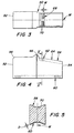
- a cutting insert 50 suitable for parting or grooving, and adapted to fit in the holder 11 of Figs. 1, 2.
- the insert 50 is similar to the prior art insert disclosed in connection with Figs. 1 and 2 in that the insert includes a body formed of a hard metal, such as cemented carbide, especially tungsten carbide, and includes a front face 52, a rear face 54, and a cutting edge 56 disposed at an upper portion of the front face.
- the insert also includes upper and lower surfaces 58, 60 each being of V-shaped cross-section and extending in a front-to-rear direction of the insert. Each of the V-shapes is bisected by a longitudinal center plane M of the insert.
- the upper surface 58 includes front and rear portions 62, 64 angled relative to one another. That is, the rear portion 64 starts at the rear face 54 and extends forwardly at a progressively increasing distance from the lower surface 60.
- the front portion 62 extends forwardly from a front end of the rear portion 64 in a direction generally parallel to the lower surface 60 and terminates at a rearwardly facing abutment surface 66 of the insert situated rearwardly of the cutting edge.
- each of the lower surface 60 and the front portion 62 of the upper surface includes recess patterns 68 situated on both sides of the mid plane M.
- Each recess pattern includes small recesses 68a which define therebetween non-recessed portions 70 of the surfaces 60, 62.
- the non-recessed portions 70 are spaced apart in the front-to-rear direction and make contact with the respective walls of the slot 13 of the holder.
- the elastic clamping force applied by the holder to the insert is divided over a smaller surface area (due to the presence of the recess pattern 68), whereby the clamping pressure (pounds per square inch) generated by the clamping force is increased, to more securely retain the insert.
- the walls 14, 15 of the holder are planar and thus relatively smooth, i.e., those walls do not extend into the recesses 68a so as to create an interference type of connection. (During a cutting operation it is possible that the forces applied to the insert could cause the recess pattern to be indented slightly into the planar wall sections 14a,b or 15a,b of the holder slot 13, but not enough to prevent the insert from later being pushed out of the slot.)
- each recess could have a width W of 0,0508-0,508 mm (.002 to .02 inches) in the front-to-rear direction, a preferred spacing S in the front-to-rear direction of 0,254-1,27 mm (.01-.05 inch) (the spacing S defining the width of each non-recessed portion 70), and a preferred depth D of 0,0127-0,0254 mm (.0005-.001 inches), depending on the insert size.
- the recesses need not extend perpendicular to the center plane M as shown in Figs. 3 and 6, but rather could be inclined at oblique angles (e.g. 10°) relative to the longitudinal center plane M.
- the recess pattern could comprise a wave-shaped micro-recess as shown at 68b in Fig. 7, thereby forming non-recessed portions 70C spaced by successive portions of the wave.
- the recess pattern could comprise any suitable shape, such as circular or elliptical recesses, for example, which create non-recessed portions.
- the clamping pressure is increased since the overall area of the surfaces 58, 60 is reduced. This tends to prevent accidental dislodgement of the insert.
Landscapes
- Engineering & Computer Science (AREA)
- Mechanical Engineering (AREA)
- Cutting Tools, Boring Holders, And Turrets (AREA)
- Magnetic Heads (AREA)
- Braking Arrangements (AREA)
Claims (7)
- Outil à tronçonner/à saigner comprenant un support (11) et un contact (50) fixé de manière amovible dans ledit support, ledit contact (50) comprenant des extrémités avant et arrière, ladite extrémité avant comprenant une arête tranchante (56), ladite extrémité arrière comprenant une face arrière (54), des surfaces supérieure et inférieure (58, 60) dudit contact étant généralement de coupe transversale en forme de V et s'étendant le long d'une direction de l'avant vers l'arrière, ladite forme en V étant bissectée par un plan médian longitudinal (M) dudit contact, ledit support comprenant : une fente s'ouvrant vers l'avant (13) formée par les parois supérieure et inférieure s'étendant vers l'avant (14, 15) de la coupe transversale en forme de V, chaque paroi définie par des sections de paroi planes mutuellement en biais, lesdites parois se faisant face l'une l'autre et mettant en prise lesdites surfaces supérieure et inférieure (58, 60) respectivement et étant ainsi fléchies de manière élastique pour monter par friction lesdites surfaces supérieure et inférieure respectivement ; au moins une desdites surfaces supérieure et inférieure (58, 60) étant proposée avec des configurations d'encastrement (68) s'étendant à l'intérieur de celles-ci et situées sur les côtés respectifs du plan médian longitudinal, chaque configuration d'encastrement configurée afin que des parties non encastrées (70) de ladite au moins surface soient espacées le long de ladite direction de l'avant vers l'arrière ; lesdites sections de paroi planes de ladite fente du support mettant en prise lesdites parties non encastrées et s'étendant à travers lesdites configurations d'encastrement, caractérisé en ce que le contact comprend une partie arrière démarrant depuis une extrémité arrière dudit contact et s'étendant vers l'avant à une distance progressivement croissante depuis ladite surface de fond, ladite partie avant s'étendant vers l'avant depuis une extrémité avant de ladite partie arrière dans une direction généralement parallèle à ladite surface de fond et se terminant au niveau d'une surface de butée faisant face vers l'arrière (66) dudit contact, chacune de ladite surface inférieure (60) et de ladite partie avant (62) de ladite surface supérieure comprenant des configurations d'encastrement situées sur les côtés respectifs dudit plan médian longitudinal et configurées pour définir lesdites parties non encastrées espacées (70) de ladite surface inférieure et de ladite partie avant.
- Outil selon la revendication 1, caractérisé en ce que les deux surfaces supérieure et inférieure possèdent lesdites configurations d'encastrement (68) et lesdites parties non encastrées (70).
- Outil selon la revendication 1, dans lequel chaque configuration d'encastrement comprend une gorge en forme d'onde (68b) formant ainsi des parties non encastrées (70c) espacées par des parties successives de l'onde.
- Outil selon la revendication 1, dans lequel chaque configuration d'encastrement comprend des gorges espacées dans la direction de l'avant vers l'arrière.
- Outil selon la revendication 1, dans lequel chaque configuration d'encastrement comprend des gorges en forme d'onde s'étendant dans ladite direction de l'avant vers l'arrière sur les côtés respectifs dudit plan médian longitudinal.
- Outil selon la revendication 1, dans lequel chaque partie non encastrée présente une largeur dans ladite direction de l'avant vers l'arrière dans la gamme de 0,254 à 1,27 mm (0,01 à 0,05 pouce).
- Outil selon la revendication 6, dans lequel chaque encastrement présente une largeur dans ladite direction de l'avant vers l'arrière dans la gamme de 0,0508 à 0,508 mm (0,002 à 0,02 pouce).
Applications Claiming Priority (2)
| Application Number | Priority Date | Filing Date | Title |
|---|---|---|---|
| US09/514,289 US6334742B1 (en) | 2000-02-28 | 2000-02-28 | Parting/grooving insert secured by friction in a holder |
| US514289 | 2000-02-28 |
Publications (3)
| Publication Number | Publication Date |
|---|---|
| EP1127640A1 EP1127640A1 (fr) | 2001-08-29 |
| EP1127640A9 EP1127640A9 (fr) | 2002-01-02 |
| EP1127640B1 true EP1127640B1 (fr) | 2003-11-26 |
Family
ID=24046564
Family Applications (1)
| Application Number | Title | Priority Date | Filing Date |
|---|---|---|---|
| EP01104241A Expired - Lifetime EP1127640B1 (fr) | 2000-02-28 | 2001-02-22 | Plaquette à tronçonner ou de rainurage, fixée par frottement |
Country Status (4)
| Country | Link |
|---|---|
| US (1) | US6334742B1 (fr) |
| EP (1) | EP1127640B1 (fr) |
| AT (1) | ATE254973T1 (fr) |
| DE (1) | DE60101280T2 (fr) |
Families Citing this family (6)
| Publication number | Priority date | Publication date | Assignee | Title |
|---|---|---|---|---|
| US6712564B1 (en) * | 2000-09-29 | 2004-03-30 | Greenleaf Technology Corporation | Tool with improved resistance to displacement |
| SE529021C2 (sv) * | 2004-09-21 | 2007-04-10 | Seco Tools Ab | Skärverktyg |
| JP5224331B2 (ja) * | 2008-02-28 | 2013-07-03 | 富山県 | 切削工具及びうねり形状の作製方法 |
| US9517509B2 (en) * | 2010-12-25 | 2016-12-13 | Kyocera Corporation | Cutting tool and method of manufacturing machined product using the same |
| JP5717885B2 (ja) * | 2012-01-30 | 2015-05-13 | 京セラ株式会社 | ホルダおよび切削工具 |
| DE102012111240A1 (de) * | 2012-11-21 | 2014-05-22 | Hartmetall-Werkzeugfabrik Paul Horn Gmbh | Spanabhebendes Werkzeug |
Family Cites Families (12)
| Publication number | Priority date | Publication date | Assignee | Title |
|---|---|---|---|---|
| US1131538A (en) * | 1914-06-20 | 1915-03-09 | George H Mason | Tool-holder. |
| US2453959A (en) * | 1945-04-19 | 1948-11-16 | Anthony Tool Company | Toolholder assembly |
| SE452713B (sv) | 1986-04-07 | 1987-12-14 | Sandvik Ab | Verktyg for avstickning samt sker for anvendning i nemnda verktyg |
| IL91815A (en) | 1989-09-28 | 1991-08-16 | Iscar Ltd | Cutting insert and cutting tool assembly incorporating such an insert |
| DE9317533U1 (de) | 1993-11-16 | 1994-02-10 | Krupp Widia Gmbh, 45145 Essen | Halter für spanabhebende Werkzeugeinsätze |
| DE4415425A1 (de) * | 1994-05-03 | 1995-11-09 | Krupp Widia Gmbh | Spanendes Werkzeug |
| IL112818A (en) * | 1995-02-28 | 1999-10-28 | Iscar Ltd | Tool holder having a grooved seat |
| DE29517683U1 (de) * | 1995-11-09 | 1996-03-07 | Grass AG, Höchst, Vorarlberg | Schublade |
| AT1323U1 (de) | 1996-04-18 | 1997-03-25 | Plansee Tizit Gmbh | Schneidwerkzeug mit klemmvorrichtung |
| SE510851C2 (sv) * | 1996-12-23 | 1999-06-28 | Sandvik Ab | Skär samt hållare för skärande metallbearbetning |
| SE511390C2 (sv) * | 1997-03-05 | 1999-09-20 | Sandvik Ab | Anordning vid fastspänning av skärplattor för skärande metallbearbetning |
| SE511934C2 (sv) * | 1997-09-24 | 1999-12-20 | Sandvik Ab | Verktyg för spånavskiljande bearbetning |
-
2000
- 2000-02-28 US US09/514,289 patent/US6334742B1/en not_active Expired - Lifetime
-
2001
- 2001-02-22 DE DE60101280T patent/DE60101280T2/de not_active Expired - Lifetime
- 2001-02-22 EP EP01104241A patent/EP1127640B1/fr not_active Expired - Lifetime
- 2001-02-22 AT AT01104241T patent/ATE254973T1/de active
Also Published As
| Publication number | Publication date |
|---|---|
| DE60101280T2 (de) | 2004-09-16 |
| DE60101280D1 (de) | 2004-01-08 |
| US6334742B1 (en) | 2002-01-01 |
| ATE254973T1 (de) | 2003-12-15 |
| EP1127640A1 (fr) | 2001-08-29 |
| EP1127640A9 (fr) | 2002-01-02 |
Similar Documents
| Publication | Publication Date | Title |
|---|---|---|
| EP0242343B1 (fr) | Outil et insert pour l'usinage | |
| KR100272500B1 (ko) | 인써트 클램핑 수단을 구비한 절삭공구 | |
| US6234727B1 (en) | Resilient clamping mechanism for inserts | |
| JP4717063B2 (ja) | 切削工具 | |
| EP0152729B1 (fr) | Outil de coupe par enlèvement de copeaux | |
| EP1013364B1 (fr) | Assemblage de porte-outil | |
| US5150992A (en) | Cutting insert and a cutting tool assembly incorporating such an insert | |
| CN102413971B (zh) | 切削工具及其所用的切削刀片 | |
| US6702529B1 (en) | Cutting tool for parting and similar operations | |
| CA1243194A (fr) | Outil de coupe | |
| EP1263543A1 (fr) | Ensemble outil de coupe | |
| EP1127640B1 (fr) | Plaquette à tronçonner ou de rainurage, fixée par frottement | |
| JP4918799B2 (ja) | 切削インサートのクランプ機構及びインサート着脱式切削工具 | |
| EP1243365A2 (fr) | Porte-outil pour une barre d' alésage | |
| JPH11104904A (ja) | 溝入れ用バイトホルダおよびそのスローアウェイチップ | |
| EP1629912B1 (fr) | Plaquette de coupe pour le rainurage profond avec une arête de coupe en palier | |
| JPH0871812A (ja) | 溝入れ用バイトおよびスローアウェイチップ | |
| JP3166500B2 (ja) | 溝入れ用バイト | |
| JP3246220B2 (ja) | 溝入れ用バイト | |
| JP2005066707A (ja) | スローアウェイチップのクランプ機構 | |
| JP2005066708A (ja) | スローアウェイチップのクランプ機構 | |
| JPH08187603A (ja) | 溝入れバイト |
Legal Events
| Date | Code | Title | Description |
|---|---|---|---|
| PUAI | Public reference made under article 153(3) epc to a published international application that has entered the european phase |
Free format text: ORIGINAL CODE: 0009012 |
|
| AK | Designated contracting states |
Kind code of ref document: A1 Designated state(s): AT BE CH CY DE DK ES FI FR GB GR IE IT LI LU MC NL PT SE TR Kind code of ref document: A1 Designated state(s): AT DE FR GB IT SE |
|
| AX | Request for extension of the european patent |
Free format text: AL;LT;LV;MK;RO;SI |
|
| 17P | Request for examination filed |
Effective date: 20010910 |
|
| 17Q | First examination report despatched |
Effective date: 20011130 |
|
| AKX | Designation fees paid |
Free format text: AT DE FR GB IT SE |
|
| GRAH | Despatch of communication of intention to grant a patent |
Free format text: ORIGINAL CODE: EPIDOS IGRA |
|
| GRAS | Grant fee paid |
Free format text: ORIGINAL CODE: EPIDOSNIGR3 |
|
| GRAA | (expected) grant |
Free format text: ORIGINAL CODE: 0009210 |
|
| AK | Designated contracting states |
Kind code of ref document: B1 Designated state(s): AT DE FR GB IT SE |
|
| REG | Reference to a national code |
Ref country code: GB Ref legal event code: FG4D |
|
| REF | Corresponds to: |
Ref document number: 60101280 Country of ref document: DE Date of ref document: 20040108 Kind code of ref document: P |
|
| PGFP | Annual fee paid to national office [announced via postgrant information from national office to epo] |
Ref country code: SE Payment date: 20040204 Year of fee payment: 4 |
|
| PG25 | Lapsed in a contracting state [announced via postgrant information from national office to epo] |
Ref country code: SE Free format text: LAPSE BECAUSE OF FAILURE TO SUBMIT A TRANSLATION OF THE DESCRIPTION OR TO PAY THE FEE WITHIN THE PRESCRIBED TIME-LIMIT Effective date: 20040226 |
|
| ET | Fr: translation filed | ||
| PLBE | No opposition filed within time limit |
Free format text: ORIGINAL CODE: 0009261 |
|
| STAA | Information on the status of an ep patent application or granted ep patent |
Free format text: STATUS: NO OPPOSITION FILED WITHIN TIME LIMIT |
|
| 26N | No opposition filed |
Effective date: 20040827 |
|
| REG | Reference to a national code |
Ref country code: GB Ref legal event code: 732E |
|
| REG | Reference to a national code |
Ref country code: GB Ref legal event code: 732E |
|
| REG | Reference to a national code |
Ref country code: FR Ref legal event code: TP |
|
| REG | Reference to a national code |
Ref country code: FR Ref legal event code: TP |
|
| REG | Reference to a national code |
Ref country code: FR Ref legal event code: PLFP Year of fee payment: 15 |
|
| PGFP | Annual fee paid to national office [announced via postgrant information from national office to epo] |
Ref country code: IT Payment date: 20150216 Year of fee payment: 15 Ref country code: DE Payment date: 20150218 Year of fee payment: 15 |
|
| PGFP | Annual fee paid to national office [announced via postgrant information from national office to epo] |
Ref country code: FR Payment date: 20150210 Year of fee payment: 15 Ref country code: AT Payment date: 20150126 Year of fee payment: 15 Ref country code: GB Payment date: 20150218 Year of fee payment: 15 |
|
| REG | Reference to a national code |
Ref country code: DE Ref legal event code: R119 Ref document number: 60101280 Country of ref document: DE |
|
| REG | Reference to a national code |
Ref country code: AT Ref legal event code: MM01 Ref document number: 254973 Country of ref document: AT Kind code of ref document: T Effective date: 20160222 |
|
| GBPC | Gb: european patent ceased through non-payment of renewal fee |
Effective date: 20160222 |
|
| REG | Reference to a national code |
Ref country code: FR Ref legal event code: ST Effective date: 20161028 |
|
| PG25 | Lapsed in a contracting state [announced via postgrant information from national office to epo] |
Ref country code: AT Free format text: LAPSE BECAUSE OF NON-PAYMENT OF DUE FEES Effective date: 20160222 |
|
| PG25 | Lapsed in a contracting state [announced via postgrant information from national office to epo] |
Ref country code: IT Free format text: LAPSE BECAUSE OF NON-PAYMENT OF DUE FEES Effective date: 20160222 |
|
| PG25 | Lapsed in a contracting state [announced via postgrant information from national office to epo] |
Ref country code: DE Free format text: LAPSE BECAUSE OF NON-PAYMENT OF DUE FEES Effective date: 20160901 Ref country code: FR Free format text: LAPSE BECAUSE OF NON-PAYMENT OF DUE FEES Effective date: 20160229 Ref country code: GB Free format text: LAPSE BECAUSE OF NON-PAYMENT OF DUE FEES Effective date: 20160222 |