EP1127674A2 - Verfahren und Vorrichtung zum Spritzgiessen von mindestens einen Hohlraum aufweisenden Formteilen - Google Patents
Verfahren und Vorrichtung zum Spritzgiessen von mindestens einen Hohlraum aufweisenden Formteilen Download PDFInfo
- Publication number
- EP1127674A2 EP1127674A2 EP01103313A EP01103313A EP1127674A2 EP 1127674 A2 EP1127674 A2 EP 1127674A2 EP 01103313 A EP01103313 A EP 01103313A EP 01103313 A EP01103313 A EP 01103313A EP 1127674 A2 EP1127674 A2 EP 1127674A2
- Authority
- EP
- European Patent Office
- Prior art keywords
- cavity
- liquid
- plastic material
- injection
- melt
- Prior art date
- Legal status (The legal status is an assumption and is not a legal conclusion. Google has not performed a legal analysis and makes no representation as to the accuracy of the status listed.)
- Granted
Links
- 238000000034 method Methods 0.000 title claims abstract description 55
- 238000001746 injection moulding Methods 0.000 title claims abstract description 16
- 239000007788 liquid Substances 0.000 claims abstract description 81
- 238000002347 injection Methods 0.000 claims abstract description 48
- 239000007924 injection Substances 0.000 claims abstract description 48
- 229920001169 thermoplastic Polymers 0.000 claims abstract description 9
- 239000004416 thermosoftening plastic Substances 0.000 claims abstract description 8
- 239000004033 plastic Substances 0.000 claims description 42
- 239000000463 material Substances 0.000 claims description 33
- 239000000155 melt Substances 0.000 claims description 26
- 239000012530 fluid Substances 0.000 claims description 23
- 230000001105 regulatory effect Effects 0.000 claims description 10
- 238000007664 blowing Methods 0.000 claims description 5
- XLYOFNOQVPJJNP-UHFFFAOYSA-N water Substances O XLYOFNOQVPJJNP-UHFFFAOYSA-N 0.000 claims description 5
- 238000003825 pressing Methods 0.000 claims description 4
- 239000012815 thermoplastic material Substances 0.000 claims description 4
- 230000015556 catabolic process Effects 0.000 claims 1
- 238000006731 degradation reaction Methods 0.000 claims 1
- 230000000630 rising effect Effects 0.000 claims 1
- 238000000465 moulding Methods 0.000 abstract description 5
- 239000007789 gas Substances 0.000 description 26
- IJGRMHOSHXDMSA-UHFFFAOYSA-N Atomic nitrogen Chemical compound N#N IJGRMHOSHXDMSA-UHFFFAOYSA-N 0.000 description 9
- 238000001816 cooling Methods 0.000 description 9
- 229910052757 nitrogen Inorganic materials 0.000 description 4
- 238000004519 manufacturing process Methods 0.000 description 2
- 238000013459 approach Methods 0.000 description 1
- 230000001174 ascending effect Effects 0.000 description 1
- 238000006243 chemical reaction Methods 0.000 description 1
- 230000008602 contraction Effects 0.000 description 1
- 230000001419 dependent effect Effects 0.000 description 1
- 238000013461 design Methods 0.000 description 1
- 238000011161 development Methods 0.000 description 1
- 238000011982 device technology Methods 0.000 description 1
- 229910001873 dinitrogen Inorganic materials 0.000 description 1
- 230000000694 effects Effects 0.000 description 1
- 238000005516 engineering process Methods 0.000 description 1
- 239000012943 hotmelt Substances 0.000 description 1
- 239000011261 inert gas Substances 0.000 description 1
- 239000000243 solution Substances 0.000 description 1
- 230000003319 supportive effect Effects 0.000 description 1
- 238000005496 tempering Methods 0.000 description 1
Images


Classifications
-
- B—PERFORMING OPERATIONS; TRANSPORTING
- B29—WORKING OF PLASTICS; WORKING OF SUBSTANCES IN A PLASTIC STATE IN GENERAL
- B29C—SHAPING OR JOINING OF PLASTICS; SHAPING OF MATERIAL IN A PLASTIC STATE, NOT OTHERWISE PROVIDED FOR; AFTER-TREATMENT OF THE SHAPED PRODUCTS, e.g. REPAIRING
- B29C45/00—Injection moulding, i.e. forcing the required volume of moulding material through a nozzle into a closed mould; Apparatus therefor
- B29C45/17—Component parts, details or accessories; Auxiliary operations
- B29C45/1703—Introducing an auxiliary fluid into the mould
-
- B—PERFORMING OPERATIONS; TRANSPORTING
- B29—WORKING OF PLASTICS; WORKING OF SUBSTANCES IN A PLASTIC STATE IN GENERAL
- B29C—SHAPING OR JOINING OF PLASTICS; SHAPING OF MATERIAL IN A PLASTIC STATE, NOT OTHERWISE PROVIDED FOR; AFTER-TREATMENT OF THE SHAPED PRODUCTS, e.g. REPAIRING
- B29C45/00—Injection moulding, i.e. forcing the required volume of moulding material through a nozzle into a closed mould; Apparatus therefor
- B29C45/17—Component parts, details or accessories; Auxiliary operations
- B29C45/1703—Introducing an auxiliary fluid into the mould
- B29C45/1704—Introducing an auxiliary fluid into the mould the fluid being introduced into the interior of the injected material which is still in a molten state, e.g. for producing hollow articles
-
- B—PERFORMING OPERATIONS; TRANSPORTING
- B29—WORKING OF PLASTICS; WORKING OF SUBSTANCES IN A PLASTIC STATE IN GENERAL
- B29C—SHAPING OR JOINING OF PLASTICS; SHAPING OF MATERIAL IN A PLASTIC STATE, NOT OTHERWISE PROVIDED FOR; AFTER-TREATMENT OF THE SHAPED PRODUCTS, e.g. REPAIRING
- B29C45/00—Injection moulding, i.e. forcing the required volume of moulding material through a nozzle into a closed mould; Apparatus therefor
- B29C45/17—Component parts, details or accessories; Auxiliary operations
- B29C45/1703—Introducing an auxiliary fluid into the mould
- B29C45/1704—Introducing an auxiliary fluid into the mould the fluid being introduced into the interior of the injected material which is still in a molten state, e.g. for producing hollow articles
- B29C45/1711—Introducing an auxiliary fluid into the mould the fluid being introduced into the interior of the injected material which is still in a molten state, e.g. for producing hollow articles and removing excess material from the mould cavity by the introduced fluid, e.g. to an overflow cavity
-
- B—PERFORMING OPERATIONS; TRANSPORTING
- B29—WORKING OF PLASTICS; WORKING OF SUBSTANCES IN A PLASTIC STATE IN GENERAL
- B29C—SHAPING OR JOINING OF PLASTICS; SHAPING OF MATERIAL IN A PLASTIC STATE, NOT OTHERWISE PROVIDED FOR; AFTER-TREATMENT OF THE SHAPED PRODUCTS, e.g. REPAIRING
- B29C45/00—Injection moulding, i.e. forcing the required volume of moulding material through a nozzle into a closed mould; Apparatus therefor
- B29C45/17—Component parts, details or accessories; Auxiliary operations
- B29C45/1703—Introducing an auxiliary fluid into the mould
- B29C45/1704—Introducing an auxiliary fluid into the mould the fluid being introduced into the interior of the injected material which is still in a molten state, e.g. for producing hollow articles
- B29C45/1706—Introducing an auxiliary fluid into the mould the fluid being introduced into the interior of the injected material which is still in a molten state, e.g. for producing hollow articles using particular fluids or fluid generating substances
- B29C2045/1707—Introducing an auxiliary fluid into the mould the fluid being introduced into the interior of the injected material which is still in a molten state, e.g. for producing hollow articles using particular fluids or fluid generating substances using a liquid, e.g. water
-
- B—PERFORMING OPERATIONS; TRANSPORTING
- B29—WORKING OF PLASTICS; WORKING OF SUBSTANCES IN A PLASTIC STATE IN GENERAL
- B29C—SHAPING OR JOINING OF PLASTICS; SHAPING OF MATERIAL IN A PLASTIC STATE, NOT OTHERWISE PROVIDED FOR; AFTER-TREATMENT OF THE SHAPED PRODUCTS, e.g. REPAIRING
- B29C45/00—Injection moulding, i.e. forcing the required volume of moulding material through a nozzle into a closed mould; Apparatus therefor
- B29C45/17—Component parts, details or accessories; Auxiliary operations
- B29C45/1703—Introducing an auxiliary fluid into the mould
- B29C45/1704—Introducing an auxiliary fluid into the mould the fluid being introduced into the interior of the injected material which is still in a molten state, e.g. for producing hollow articles
- B29C45/1706—Introducing an auxiliary fluid into the mould the fluid being introduced into the interior of the injected material which is still in a molten state, e.g. for producing hollow articles using particular fluids or fluid generating substances
- B29C2045/1707—Introducing an auxiliary fluid into the mould the fluid being introduced into the interior of the injected material which is still in a molten state, e.g. for producing hollow articles using particular fluids or fluid generating substances using a liquid, e.g. water
- B29C2045/1708—Introducing an auxiliary fluid into the mould the fluid being introduced into the interior of the injected material which is still in a molten state, e.g. for producing hollow articles using particular fluids or fluid generating substances using a liquid, e.g. water removing the liquid from the hollow
-
- B—PERFORMING OPERATIONS; TRANSPORTING
- B29—WORKING OF PLASTICS; WORKING OF SUBSTANCES IN A PLASTIC STATE IN GENERAL
- B29C—SHAPING OR JOINING OF PLASTICS; SHAPING OF MATERIAL IN A PLASTIC STATE, NOT OTHERWISE PROVIDED FOR; AFTER-TREATMENT OF THE SHAPED PRODUCTS, e.g. REPAIRING
- B29C45/00—Injection moulding, i.e. forcing the required volume of moulding material through a nozzle into a closed mould; Apparatus therefor
- B29C45/17—Component parts, details or accessories; Auxiliary operations
- B29C45/1703—Introducing an auxiliary fluid into the mould
- B29C45/1704—Introducing an auxiliary fluid into the mould the fluid being introduced into the interior of the injected material which is still in a molten state, e.g. for producing hollow articles
- B29C45/1706—Introducing an auxiliary fluid into the mould the fluid being introduced into the interior of the injected material which is still in a molten state, e.g. for producing hollow articles using particular fluids or fluid generating substances
- B29C2045/1709—Introducing an auxiliary fluid into the mould the fluid being introduced into the interior of the injected material which is still in a molten state, e.g. for producing hollow articles using particular fluids or fluid generating substances using a cooling fluid
-
- B—PERFORMING OPERATIONS; TRANSPORTING
- B29—WORKING OF PLASTICS; WORKING OF SUBSTANCES IN A PLASTIC STATE IN GENERAL
- B29C—SHAPING OR JOINING OF PLASTICS; SHAPING OF MATERIAL IN A PLASTIC STATE, NOT OTHERWISE PROVIDED FOR; AFTER-TREATMENT OF THE SHAPED PRODUCTS, e.g. REPAIRING
- B29C45/00—Injection moulding, i.e. forcing the required volume of moulding material through a nozzle into a closed mould; Apparatus therefor
- B29C45/17—Component parts, details or accessories; Auxiliary operations
- B29C45/1703—Introducing an auxiliary fluid into the mould
- B29C45/1704—Introducing an auxiliary fluid into the mould the fluid being introduced into the interior of the injected material which is still in a molten state, e.g. for producing hollow articles
- B29C45/1711—Introducing an auxiliary fluid into the mould the fluid being introduced into the interior of the injected material which is still in a molten state, e.g. for producing hollow articles and removing excess material from the mould cavity by the introduced fluid, e.g. to an overflow cavity
- B29C2045/1712—Introducing an auxiliary fluid into the mould the fluid being introduced into the interior of the injected material which is still in a molten state, e.g. for producing hollow articles and removing excess material from the mould cavity by the introduced fluid, e.g. to an overflow cavity plastic material flowing back into the injection unit
-
- B—PERFORMING OPERATIONS; TRANSPORTING
- B29—WORKING OF PLASTICS; WORKING OF SUBSTANCES IN A PLASTIC STATE IN GENERAL
- B29C—SHAPING OR JOINING OF PLASTICS; SHAPING OF MATERIAL IN A PLASTIC STATE, NOT OTHERWISE PROVIDED FOR; AFTER-TREATMENT OF THE SHAPED PRODUCTS, e.g. REPAIRING
- B29C45/00—Injection moulding, i.e. forcing the required volume of moulding material through a nozzle into a closed mould; Apparatus therefor
- B29C45/17—Component parts, details or accessories; Auxiliary operations
- B29C45/1703—Introducing an auxiliary fluid into the mould
- B29C45/1704—Introducing an auxiliary fluid into the mould the fluid being introduced into the interior of the injected material which is still in a molten state, e.g. for producing hollow articles
- B29C2045/1727—Introducing an auxiliary fluid into the mould the fluid being introduced into the interior of the injected material which is still in a molten state, e.g. for producing hollow articles using short shots of moulding material
-
- B—PERFORMING OPERATIONS; TRANSPORTING
- B29—WORKING OF PLASTICS; WORKING OF SUBSTANCES IN A PLASTIC STATE IN GENERAL
- B29C—SHAPING OR JOINING OF PLASTICS; SHAPING OF MATERIAL IN A PLASTIC STATE, NOT OTHERWISE PROVIDED FOR; AFTER-TREATMENT OF THE SHAPED PRODUCTS, e.g. REPAIRING
- B29C45/00—Injection moulding, i.e. forcing the required volume of moulding material through a nozzle into a closed mould; Apparatus therefor
- B29C45/16—Making multilayered or multicoloured articles
Definitions
- the invention further relates to a device for injection molding of at least one cavity having molded parts made of thermoplastic Plastic material.
- the generic method is the gas internal pressure method at Manufacture of molded parts made of thermoplastic material known and widespread. Such a method is known from, for example US 4,101,617. It is in the still molten plastic melt a fluid is introduced under pressure. By so inside The pressure generated by the melt will melt against the cavity wall the injection mold pressed; Sink marks due to volume contraction when cooling down are avoided.
- Nitrogen gas As a fluid, which is injected into the melt under pressure, is commonly used Nitrogen gas used. It has the advantage of being inert Gas does not undergo any chemical reaction in the hot melt. there the disadvantage is accepted that the nitrogen is usually quite is expensive to manufacture. Either the injection molding device has to Nitrogen can be supplied from bottles or the gas is on site - at Greater gas demand - obtained by means of molecular filters.
- EP 0 400 308 B1 proposes after gas injection into the melt the gas can escape at a point away from the injection point allow; then a circulation of the gas through the created cavity. There is a cooler in the gas circuit integrated. This is supposed to accelerate the cooling process of the melt take place because cooled gas is fed in a closed circuit becomes.
- the invention is therefore based on the object of further developing the injection molding process of the generic type in such a way that the disadvantages mentioned are avoided.
- the method and the associated device should therefore make it possible to do without the use of expensive nitrogen.
- the shortest possible cooling time should be realizable, which significantly shortens the injection molding process.
- the method is also intended to ensure that the flow of the melt into the injection mold is as homogeneous as possible, so that changeover markings can be avoided as far as possible.
- the main idea of the invention is based on the fact that in the Melt to be injected fluid a liquid with high heat capacity is used, in connection with the partial filling of the cavity can be achieved that first an efficient use of Plastic material is made.
- By partially filling the cavity with Melt in combination with the use of high liquid Heat capacity is achieved that a quick cooling process takes place, so that the cycle time of the injection molding cycle is reduced significantly can be. It has surprisingly been found that by the characteristics mentioned hardly occur flow marks that otherwise to fear and observe in the case of the internal gas pressure process are. This is due to the comparable viscosity of the liquid melt returned with the injected liquid of high heat capacity.
- a part of the still molten plastic material from the cavity (5) into a demoldable secondary cavity (8) is ousted.
- the flow of plastic material from the cavity (5) in the secondary cavity (8) is preferably controlled by valve means (9), which are opened or closed according to the time schedule. This is a targeted influence on the overflow of the melt possible from the main to the secondary cavity.
- the liquid can flow along the melt flow path (4) through the sprue area (11) are injected into the cavity (5) or alternatively for this purpose directly into the cavity (5) by means of an injection nozzle (10).
- a further improvement in the flow behavior of the melt or Control of this behavior arises if, before the injection of the thermoplastic melt in the cavity (5) opposite one the ambient pressure is increased by introducing a gas is built up.
- This gas pressure can be reduced during step b) above. only gradually be dismantled.
- the reduction in gas pressure can be in Dependent on being controlled or regulated, such as the injection pressure the liquid increases during its injection.
- the liquid before it is injected into the still molten plastic material is tempered.
- the Liquid is cooled to a predetermined temperature range.
- a temperature range between 0 ° C. is particularly advantageous and 20 ° C, preferably between 4 ° C and 15 ° C, provided. It can but may also be necessary, for example in the case of materials shock-like cooling will damage the liquid on you to heat the specified temperature range.
- a temperature range between 20 ° C and 150 ° C is preferred between 40 ° C and 100 ° C.
- the following process step is carried out after allowing to cool and before demolding: c ') Pressing in compressed gas, preferably compressed air, along the path by which the liquid was injected into the plastic material, and blowing the liquid out of the cavity (1) of the molded part (2) at at least one blow-out point (12) a location that is distant from the fluid entry location.
- compressed gas preferably compressed air
- the blow-out point (12) is preferred in the region of the end of the flow path arranged of the plastic material.
- the following process step is carried out at the time mentioned: c ") pressing in compressed gas, preferably compressed air, at a gas input point which is distant from the point at which the liquid was injected into the plastic material, and blowing out the liquid from the cavity (1) of the molded part (2) via the point, where the liquid was injected into the plastic material.
- compressed gas preferably compressed air
- the liquid can also be sucked out. It is then provided that the following process step is carried out: c ''') Applying a vacuum at a location fluidically connected to the liquid-filled cavity (1) in order to suck the liquid in the cavity (1) out of the cavity (1).
- the vacuum is advantageously applied to the injection nozzle (10) for liquid created.
- the molding process during the injection of melt and of liquid as well as during the curing of the material corresponding control or regulation of the media pressures is influenced favorably become. It is therefore advantageously provided that on the liquid introduced into the plastic melt during the above Steps b) and / or c) a pressure is exerted according to a predetermined Time profile is regulated or controlled.
- the pressure profile can regulated according to a pulsating ascending and descending course or be controlled; is above all one at a sinusoidal predetermined constant pressure value running pressure curve thought.
- the pressure in a first time phase at a first, preferably constant, level and in a later, second time phase on a second, preferably constant, level is regulated or controlled, the first pressure level is lower than the second.
- Water or oil is preferred as the liquid with high heat capacity in question.
- the device is characterized by means (13) to remove, in particular suction, the in the cavity (1) of the Shaped part (2) located fluid, the fluid having a liquid is high heat capacity.
- the means (13) is a nozzle through which the liquid from the Cavity (1) can be blown out.
- the remedy is one Device for generating a vacuum, which is connected to the means (10) for Injecting the liquid can be connected.
- the device is a Injection element (14) with which either liquid (W) or Gas (G) into the cavity (5) of the injection mold (6) are entered can.
- the injection element therefore has a switchover option from one medium to another.
- Fig. List an injection molding device can be seen, the one injection unit 3, which produces plastic melt in the usual way and in injects an injection mold 6.
- the tool 6 has a cavity 5 with a cavity wall 7.
- the plastic melt is along a melt flow path 4 from the injection unit 3 into the tool 6 sprayed.
- the molded part 2 to be produced has a cavity 1, on the one hand makes the part lighter and requires less material, which it on the other hand, allows in while cooling the melt the cavity 5, this is pressed against the cavity wall 7.
- the produced Molded parts 2 therefore have a particularly good surface quality.
- the overflow can be controlled or regulated by valve means 9.
- the fluid is injected via the injection nozzle 10. As can be seen, the fluid therefore spreads along the melt flow path 4 in the direction of the cavity 5.
- a fluid with a high thermal capacity comes as the fluid for use.
- the cavity 5 is initially partial before the liquid is injected filled, it has been shown to be advantageous that they are not with more than 80% of their volume is filled. Then the liquid preferably water, injected. By tempering the liquid, namely by cooling to a value between 4 ° C and 15 ° C, can be achieved that a very fast curing of the Plastic melt takes place, whereby it is sufficient, the plastic material to cool in such a way that it is self-supporting.
- Fig. 1 it can be seen that the input of the liquid along the Melt flow path 4 takes place in the region of the sprue 11.
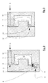
- the more detailed Design of the area of the injection mold is in the Figures 2 and 3 reproduced.
- melt S is in the gate 11 in the Cavity 5 injected.
- the melt flows, as already mentioned above at the end of the flow path from the main cavity 5 into the secondary cavity 8, the overflow being regulated by means of valve means 9. After this at least partially curing must be the liquid that the Fills cavity 1, can be removed from this. To do this Compressed air is introduced into the liquid 10 injector.
- the cavity 1 extends over the Cavity 5 out into the secondary cavity, which is due to the input of liquid into the melt.
- a blow-out nozzle 13 positioned in the area of the overflow cavity 8, namely at the blow-out point 12 for liquid.
- By injecting compressed air through the nozzle 10 All liquid can be blown out of the cavity 1 again. It is driven out by the blow-out nozzle 13. It can be - more supportive Way - a vacuum is applied to the blow-out nozzle 13.
- the liquid can also be blown out if is worked without overflow, which is illustrated in Fig. 3.
- Fig. 4 it can be seen that a special device advantageous embodiment results when an injection element 14 is used through which either liquid (water) W or compressed air (Gas) G can be injected. 4, the injector 10 is sufficient for liquid and gas in the area of the melt flow path 4 from the injection unit 3 into the mold cavity.
- the combined injection element 14 for liquid and Arrange gas in such a way that liquid or Gas is injected directly into the cavity of the tool.
- the method described above can also be used advantageously for otherwise use the usual injection molding process.
- it can also be used well if the molded part consists of more than one Plastic component is injected (2-component process).
- the liquid can also be fed into the sprue distributor take place, whereby several partial cavities are supplied with liquid can.
Landscapes
- Engineering & Computer Science (AREA)
- Manufacturing & Machinery (AREA)
- Mechanical Engineering (AREA)
- Injection Moulding Of Plastics Or The Like (AREA)
- Moulds For Moulding Plastics Or The Like (AREA)
Abstract
Description
c') Einpressen von Druckgas, vorzugsweise Druckluft, entlang des Weges, über den die Flüssigkeit in das Kunststoffmaterial eingespritzt wurde, und Ausblasen der Flüssigkeit aus dem Hohlraum (1) des Formteils (2) an mindestens einer Ausblasstelle (12), die sich an einer Stelle befindet, die von der Eingabestelle der Flüssigkeit entfernt ist.
c") Einpressen von Druckgas, vorzugsweise Druckluft, an einer Gaseingabestelle, die von der Stelle entfernt ist, an der die Flüssigkeit in das Kunststoffmaterial eingespritzt wurde, und Ausblasen der Flüssigkeit aus dem Hohlraum (1) des Formteils (2) über die Stelle, an der die Flüssigkeit in das Kunststoffmaterial eingespritzt wurde.
c''') Anlegen eines Vakuums an einer fluidisch mit dem flüssigkeitsgefüllten Hohlraum (1) in Verbindung stehenden Stelle, um die sich im Hohlraum (1) befindliche Flüssigkeit aus dem Hohlraum (1) abzusaugen.
- eine Einspritzeinheit (3),
- ein Spritzgießwerkzeug (6) mit einer Kavität (5), das einen Schmelzefließweg (4) aufweist, über den schmelzflüssiges Kunststoffmaterial in die Kavität (5) eingebracht werden kann, und
- Mittel (10) zum Einspritzten eines Fluids.
- Fig. 1
- den schematischen Schnitt durch eine Spritzgießvorrichtung;
- Fig. 2
- den schematischen Schnitt durch ein Spritzgießwerkzeug mit Nebenkavität;
- Fig. 3
- denselben Schnitt wie in Fig. 2, jedoch ohne Nebenkavität;
- Fig. 4
- einen Ausschnitt durch den Einspritzbereich für Schmelze und Flüssigkeit.
- 1
- Hohlraum
- 2
- Formteil
- 3
- Einspritzeinheit
- 4
- Schmelzefließweg
- 5
- Kavität
- 6
- Spritzgießwerkzeug
- 7
- Wandungen der Kavität
- 8
- Nebenkavität
- 9
- Ventilmittel
- 10
- Einspritzdüse für Flüssigkeit
- 11
- Angußbereich
- 12
- Ausblasstelle für Flüssigkeit
- 13
- Ausblasdüse
- 14
- Einspritzelement
- S
- Schmelze
- W
- Flüssigkeit (Wasser)
- F
- Gas
Claims (29)
- Verfahren zum Spritzgießen von mindestens einen Hohlraum (1) aufweisenden Formteilen (2) aus thermoplastischem Kunststoffmaterial, das die Schritte aufweist:dadurch gekennzeichnet,a) Einspritzen von thermoplastischer Kunststoffschmelze von einer Einspritzeinheit (3) entlang eines Schmelzefließweges (4) in die Kavität (5) eines Spritzgießwerkzeugs (6);b) Einspritzen eines Fluids in das noch schmelzflüssige Kunststoffmaterial, so daß dieses an die Wandungen (7) der Kavität (5) gepreßt wird;c) Abkühlenlassen des Kunststoffmaterials, bis dieses selbsttragend das Formteil (2) bildet;d) Entformen des Formteils (2) aus der Kavität (5) des Spritzgießwerkzeugs (6);daß die Füllung der Kavität (5) mit Kunststoffschmelze gemäß Schritt a) so erfolgt, daß die Kavität (5) nicht vollständig mit Kunststoffschmelze, vorzugsweise nur zu maximal 80 % des Kavitätsvolumens, gefüllt wird, unddaß als Fluid, das gemäß Schritt b) in das noch schmelzflüssige Kunststoffmaterial eingespritzt wird, eine Flüssigkeit mit hoher Wärmekapazität eingesetzt wird,wobei die vollständige Bedeckung der Oberfläche der Kavität (5) erst durch das Einspritzen der Flüssigkeit in das schmelzflüssige Kunststoffmaterial erfolgt.
- Verfahren nach Anspruch 1, dadurch gekennzeichnet, daß während des Verfahrensschrittes b) gemäß Anspruch 1 ein Teil des noch schmelzflüssigen Kunststoffmaterials aus der Kavität (5) in eine entformbare Nebenkavität (8) verdrängt wird.
- Verfahren nach Anspruch 2, dadurch gekennzeichnet, daß der Fluß von Kunststoffmaterial von der Kavität (5) in die Nebenkavität (8) durch Ventilmittel (9) gesteuert wird, die gemäß zeitlicher Vorgabe geöffnet bzw. geschlossen werden.
- Verfahren nach einem der Ansprüche 1 bis 3, dadurch gekennzeichnet, daß die Flüssigkeit entlang des Schmelzefließweges (4) durch den Angußbereich (11) in die Kavität (5) eingespritzt wird.
- Verfahren nach einem der Ansprüche 1 bis 3, dadurch gekennzeichnet, daß die Flüssigkeit direkt mittels einer Einspritzdüse (10) in die Kavität (5) eingespritzt wird.
- Verfahren nach Anspruch 5, dadurch gekennzeichnet, daß ein Teil des sich in der Kavität (5) befindlichen Kunststoffmaterials während Schritt b) gemäß Anspruch 1 durch die eingespritzte Flüssigkeit in Richtung auf die Einspritzeinheit (3) zu aus der Kavität (5) heraus zurückgetrieben wird.
- Verfahren nach einem der Ansprüche 1 bis 6, dadurch gekennzeichnet, daß vor dem Einspritzen der thermoplastischen Kunststoffschmelze nach Schritt a) gemäß Anspruch 1 in der Kavität (5) ein gegenüber dem Umgebungsdruck erhöhter Druck durch Einbringen eines Gases aufgebaut wird.
- Verfahren nach Anspruch 7, dadurch gekennzeichnet, daß der Gasdruck während des Schrittes b) gemäß Anspruch 1 allmählich abgebaut wird.
- Verfahren nach Anspruch 8, dadurch gekennzeichnet, daß der Abbau des Gasdruckes in Abhängigkeit davon gesteuert oder geregelt wird, wie der Einspritzdruck der Flüssigkeit während des Schrittes b) gemäß Anspruch 1 zunimmt.
- Verfahren nach einem der Ansprüche 1 bis 9, dadurch gekennzeichnet, daß nach Schritt b) und vor Schritt c) gemäß Anspruch 1 des weiteren Druckgas in den durch die Flüssigkeit gebildeten Hohlraum (1) eingebracht wird.
- Verfahren nach einem der Ansprüche 1 bis 10, dadurch gekennzeichnet, daß die Flüssigkeit vor dem Einspritzen in das noch schmelzflüssige Kunststoffmaterial nach Schritt a) gemäß Anspruch 1 temperiert wird.
- Verfahren nach Anspruch 11, dadurch gekennzeichnet, daß die Flüssigkeit auf einen vorgegebenen Temperaturbereich gekühlt wird.
- Verfahren nach Anspruch 12, dadurch gekennzeichnet, daß der vorgegebene Temperaturbereich zwischen 0 °C und 20 °C, vorzugsweise zwischen 4 °C und 15 °C, liegt
- . Verfahren nach Anspruch 12, dadurch gekennzeichnet, daß der vorgegebene Temperaturbereich zwischen 20 °C und 150 °C, vorzugsweise zwischen 40 °C und 100 °C, liegt.
- Verfahren nach einem der Ansprüche 1 bis 14, dadurch gekennzeichnet, daß nach Schritt c) und vor Schritt d) gemäß Anspruch 1 folgender Verfahrensschritt ausgeführt wird:
c') Einpressen von Druckgas, vorzugsweise Druckluft, entlang des Weges, über den die Flüssigkeit in das Kunststoffmaterial eingespritzt wurde, und Ausblasen der Flüssigkeit aus dem Hohlraum (1) des Formteils (2) an mindestens einer Ausblasstelle (12), die sich an einer Stelle befindet, die von der Eingabestelle der Flüssigkeit entfernt ist. - Verfahren nach Anspruch 15, dadurch gekennzeichnet, daß die Ausblasstelle (12) im Bereich des Fließwegendes des Kunststoffmaterials angeordnet wird.
- Verfahren nach einem der Ansprüche 1 bis 14, dadurch gekennzeichnet, daß nach Schritt c) und vor Schritt d) gemäß Anspruch 1 folgender Verfahrensschritt ausgeführt wird:
c") Einpressen von Druckgas, vorzugsweise Druckluft, an einer Gaseingabestelle, die von der Stelle entfernt ist, an der die Flüssigkeit in das Kunststoffmaterial eingespritzt wurde, und Ausblasen der Flüssigkeit aus dem Hohlraum (1) des Formteils (2) über die Stelle, an der die Flüssigkeit in das Kunststoffmaterial eingespritzt wurde. - Verfahren nach einem der Ansprüche 1 bis 14, dadurch gekennzeichnet, daß nach Schritt c) und vor Schritt d) gemäß Anspruch 1 folgender Verfahrensschritt ausgeführt wird:
c''') Anlegen eines Vakuums an einer fluidisch mit dem flüssigkeitsgefüllten Hohlraum (1) in Verbindung stehenden Stelle, um die sich im Hohlraum (1) befindliche Flüssigkeit aus dem Hohlraum (1) abzusaugen. - Verfahren nach Anspruch 18, dadurch gekennzeichnet, daß das Vakuum an der Einspritzdüse (10) für Flüssigkeit angelegt wird.
- Verfahren nach einem der Ansprüche 1 bis 19, dadurch gekennzeichnet, daß auf die in die Kunststoffschmelze eingebrachte Flüssigkeit während der Schritte b) und/oder c) gemäß Anspruch 1 ein Druck ausgeübt wird, der gemäß einem vorgegebenen Zeitprofil geregelt oder gesteuert wird.
- Verfahren nach Anspruch 20, dadurch gekennzeichnet, daß der Druck gemäß einem pulsierend an- und absteigenden Profil geregelt oder gesteuert wird.
- Verfahren nach Anspruch 21, dadurch gekennzeichnet, daß der Druckverlauf sinusförmig um einen vorgegebenen konstanten Druckwert verläuft.
- Verfahren nach Anspruch 22, dadurch gekennzeichnet, daß der Druck in einer ersten Zeitphase auf einem ersten, vorzugsweise konstanten, Niveau und in einer späteren, zweiten Zeitphase auf einem zweiten, vorzugsweise konstanten, Niveau geregelt oder gesteuert wird, wobei das erste Druckniveau niedriger als das zweite ist.
- Verfahren nach einem der Ansprüche 1 bis 23, dadurch gekennzeichnet, daß als Flüssigkeit Wasser eingesetzt wird.
- Verfahren nach einem der Ansprüche 1 bis 23, dadurch gekennzeichnet, daß als Flüssigkeit Öl eingesetzt wird.
- Vorrichtung zum Spritzgießen von mindestens einen Hohlraum (1) aufweisenden Formteilen (2) aus thermoplastischem Kunststoffmaterial zur Durchführung des Verfahrens nach einem der Ansprüche 1 bis 24, die aufweist:gekennzeichnet durcheine Einspritzeinheit (3),ein Spritzgießwerkzeug (6) mit einer Kavität (5), das einen Schmelzefließweg (4) aufweist, über den schmelzflüssiges Kunststoffmaterial in die Kavität (5) eingebracht werden kann, undMittel (10) zum Einspritzten eines Fluids,
Mittel (13) zum Entfernen, insbesondere Absaugen, des sich im Hohlraum (1) des Formteils (2) befindlichen Fluids, wobei das Fluid eine Flüssigkeit mit hoher Wärmekapazität ist. - Vorrichtung nach Anspruch 26, dadurch gekennzeichnet, daß das Mittel (13) eine Düse ist, über die die Flüssigkeit aus dem Hohlraum (1) ausgeblasen werden kann.
- Vorrichtung nach Anspruch 26, dadurch gekennzeichnet, daß das Mittel eine Vorrichtung zur Erzeugung eines Vakuums ist, die an das Mittel (10) zum Einspritzen der Flüssigkeit angeschlossen werden kann.
- Vorrichtung nach einem der Ansprüche 26 bis 28, dadurch gekennzeichnet, daß die Vorrichtung ein Einspritzelement (14) aufweist, mit dem wahlweise Flüssigkeit (W) oder Gas (G) in die Kavität (5) des Spritzgießwerkzeugs (6) eingegeben werden kann.
Applications Claiming Priority (2)
| Application Number | Priority Date | Filing Date | Title |
|---|---|---|---|
| DE10007994A DE10007994C2 (de) | 2000-02-22 | 2000-02-22 | Verfahren und Vorrichtung zum Spritzgiessen von mindestens einen Hohlraum aufweisenden Formteilen |
| DE10007994 | 2000-02-22 |
Publications (3)
| Publication Number | Publication Date |
|---|---|
| EP1127674A2 true EP1127674A2 (de) | 2001-08-29 |
| EP1127674A3 EP1127674A3 (de) | 2002-02-06 |
| EP1127674B1 EP1127674B1 (de) | 2003-11-05 |
Family
ID=7631801
Family Applications (1)
| Application Number | Title | Priority Date | Filing Date |
|---|---|---|---|
| EP01103313A Expired - Lifetime EP1127674B1 (de) | 2000-02-22 | 2001-02-13 | Verfahren zum Spritzgiessen von mindestens einen Hohlraum aufweisenden Formteilen |
Country Status (6)
| Country | Link |
|---|---|
| US (1) | US6713014B2 (de) |
| EP (1) | EP1127674B1 (de) |
| JP (1) | JP4741095B2 (de) |
| AT (1) | ATE253442T1 (de) |
| DE (2) | DE10007994C2 (de) |
| ES (1) | ES2210044T3 (de) |
Cited By (1)
| Publication number | Priority date | Publication date | Assignee | Title |
|---|---|---|---|---|
| EP2474405A1 (de) * | 2011-01-11 | 2012-07-11 | Linde Aktiengesellschaft | Gasinnendruckverfahren zur Herstellung von Kunststoffteilen |
Families Citing this family (9)
| Publication number | Priority date | Publication date | Assignee | Title |
|---|---|---|---|---|
| GB2389069B (en) * | 1999-07-17 | 2004-05-12 | Univ Warwick | Gas injection moulding method and apparatus |
| US6716387B2 (en) * | 2001-02-28 | 2004-04-06 | Alliance Systems, Inc. | Process for pressure assisted molding of hollow articles |
| GB0314451D0 (en) * | 2003-06-20 | 2003-07-23 | Cinpres Gas Injection Ltd | Liquid assisted moulding method and apparatus |
| DE102004017387A1 (de) * | 2004-04-05 | 2005-10-20 | Lothar Kallien | Verfahren zur Herstellung von Gussteilen |
| DE102004020579A1 (de) * | 2004-04-27 | 2005-12-01 | Mekra Lang Gmbh & Co. Kg | Verfahren zum Herstellen von Spritzgussformteilen, insbesondere von Teilen von Kraftfahrzeugspiegeln |
| JP4777667B2 (ja) * | 2005-02-07 | 2011-09-21 | 株式会社シスコ | 金型の加熱冷却システム及び中空射出成形品用の金型装置 |
| KR101703888B1 (ko) * | 2015-09-24 | 2017-02-07 | 주식회사 유도 | 수지의 난류 유동장치가 구비된 핫런너 시스템 |
| WO2018116332A1 (en) | 2016-12-21 | 2018-06-28 | Sapa S.R.L. | Method for the injection molding of internally hollow parts |
| IT201800002428A1 (it) | 2018-02-06 | 2019-08-06 | Sapa S P A | Macchinario e metodo di stampaggio a iniezione di elementi cavi |
Family Cites Families (32)
| Publication number | Priority date | Publication date | Assignee | Title |
|---|---|---|---|---|
| IT1027943B (it) * | 1973-12-28 | 1978-12-20 | Asahi Dow Ltd | Metodo di produzione di articoli sagonati da materiali di resina sintetica |
| DE2501314A1 (de) | 1975-01-15 | 1976-07-22 | Roehm Gmbh | Spritzgiessen hohler formteile aus thermoplastischen kunststoffen, insbesondere fuer den bausektor |
| JPS59383B2 (ja) * | 1977-01-05 | 1984-01-06 | 旭化成株式会社 | 型物の成形法 |
| JPS53102960A (en) | 1977-02-21 | 1978-09-07 | Asahi Chem Ind Co Ltd | Injection mold |
| DE3913109C5 (de) * | 1989-04-21 | 2010-03-18 | Ferromatik Milacron Maschinenbau Gmbh | Verfahren zum Spritzgießen fluidgefüllter Kunststoffkörper und Vorrichtung zur Durchführung des Verfahrens |
| DE3917366A1 (de) | 1989-05-29 | 1991-01-10 | Schade Kg | Verfahren zum herstellen von hohlgespritzten formkoerpern aus kunststoff und vorrichtung zur durchfuehrung des verfahrens |
| JPH0462118A (ja) * | 1990-06-26 | 1992-02-27 | Isuzu Motors Ltd | 中空樹脂成形品の成形方法 |
| JPH0712619B2 (ja) | 1990-07-18 | 1995-02-15 | 豊田合成株式会社 | 射出中空成形型 |
| US5198240A (en) | 1990-07-19 | 1993-03-30 | Nitrojection Corporation | Pressurization control unit for a gas-assisted injection molding machine |
| US5139714A (en) | 1991-06-03 | 1992-08-18 | Siebolt Hettinga | Process for injection molding a hollow plastic article |
| JP2971198B2 (ja) * | 1991-06-27 | 1999-11-02 | 本田技研工業株式会社 | 中空成形品のガス注入方法及び装置 |
| JPH082547B2 (ja) * | 1991-08-13 | 1996-01-17 | 豊田合成株式会社 | 中空成形法 |
| JPH0712623B2 (ja) | 1992-03-16 | 1995-02-15 | 株式会社日本製鋼所 | 中空部分を有する成形品の射出成形方法及び装置 |
| DE4219915A1 (de) | 1992-06-17 | 1993-12-23 | Linde Ag | Herstellung von Spritzgußteilen aus thermoplastischen Kunststoffen |
| US5505891A (en) * | 1992-07-29 | 1996-04-09 | Shah; Chandrakant S. | Method of and apparatus for dual fluid injection molding |
| DE4240017C2 (de) * | 1992-11-27 | 2001-03-15 | Wolf Woco & Co Franz J | Verfahren zur Herstellung von zumindest zweiseitig offenen hohlen Formteilen |
| DE9316984U1 (de) | 1993-11-06 | 1994-01-20 | Hydac Technology Gmbh, 66280 Sulzbach | Zentralversorgungseinheit |
| JPH07124987A (ja) * | 1993-11-08 | 1995-05-16 | Asahi Chem Ind Co Ltd | 中空射出成形方法 |
| JPH07308931A (ja) * | 1994-05-17 | 1995-11-28 | Sekisui Chem Co Ltd | 中空型物の成形方法 |
| JPH07314485A (ja) * | 1994-05-24 | 1995-12-05 | Sekisui Chem Co Ltd | 射出成形品の製造方法 |
| DE19518964C2 (de) * | 1995-05-23 | 1998-04-09 | Eldra Kunststofftechnik Gmbh | Verfahren und Vorrichtung zum Spritzgießen hohlgeblasener Kunststoffkörper |
| DE19518963C2 (de) | 1995-05-23 | 1998-04-09 | Eldra Kunststofftechnik Gmbh | Verfahren und Vorrichtung zum Spritzgießen hohlgeblasener Kunststoffkörper |
| US5705201A (en) * | 1995-09-01 | 1998-01-06 | Ibar; Jean-Pierre | Apparatus for controlling gas assisted injection molding to produce hollow and non-hollow plastic parts and modify their physical characteristics |
| DE19543944C2 (de) * | 1995-11-25 | 1998-04-09 | Battenfeld Gmbh | Verfahren zum Herstellen von Kunststoffgegenständen |
| JPH10249877A (ja) * | 1997-03-12 | 1998-09-22 | Ricoh Co Ltd | 長軸部材の成形装置及びその成形方法 |
| DE19613134C2 (de) * | 1996-04-01 | 2000-07-27 | Battenfeld Gmbh | Verfahren und Vorrichtung zum Herstellen von Kunststoffgegenständen |
| JPH10156856A (ja) | 1996-11-29 | 1998-06-16 | Beishin Kogyo Kk | 合成樹脂成形品の成形方法 |
| SE508097C2 (sv) | 1996-12-04 | 1998-08-24 | Volvo Lastvagnar Ab | Sätt och anordning för framställning av en ihålig plastdetalj |
| GB2322094B (en) | 1997-02-14 | 2001-12-05 | Peter Michael Woodworth | Method and apparatus for injection moulding of plastics material |
| DE19903682A1 (de) * | 1999-02-02 | 2000-08-03 | Ver Foerderung Inst Kunststoff | Hohlkörper aus polymeren Werkstoffen |
| US6579489B1 (en) | 1999-07-01 | 2003-06-17 | Alliance Gas Systems, Inc. | Process for gas assisted and water assisted injection molding |
| JP2001047472A (ja) | 1999-08-12 | 2001-02-20 | Canon Inc | 射出成形用金型 |
-
2000
- 2000-02-22 DE DE10007994A patent/DE10007994C2/de not_active Expired - Fee Related
-
2001
- 2001-02-13 AT AT01103313T patent/ATE253442T1/de active
- 2001-02-13 DE DE50100886T patent/DE50100886D1/de not_active Expired - Lifetime
- 2001-02-13 ES ES01103313T patent/ES2210044T3/es not_active Expired - Lifetime
- 2001-02-13 EP EP01103313A patent/EP1127674B1/de not_active Expired - Lifetime
- 2001-02-21 US US09/790,212 patent/US6713014B2/en not_active Expired - Lifetime
- 2001-02-22 JP JP2001046561A patent/JP4741095B2/ja not_active Expired - Fee Related
Cited By (1)
| Publication number | Priority date | Publication date | Assignee | Title |
|---|---|---|---|---|
| EP2474405A1 (de) * | 2011-01-11 | 2012-07-11 | Linde Aktiengesellschaft | Gasinnendruckverfahren zur Herstellung von Kunststoffteilen |
Also Published As
| Publication number | Publication date |
|---|---|
| ATE253442T1 (de) | 2003-11-15 |
| EP1127674B1 (de) | 2003-11-05 |
| DE50100886D1 (de) | 2003-12-11 |
| JP2001232656A (ja) | 2001-08-28 |
| DE10007994A1 (de) | 2001-09-06 |
| US6713014B2 (en) | 2004-03-30 |
| US20010017433A1 (en) | 2001-08-30 |
| EP1127674A3 (de) | 2002-02-06 |
| DE10007994C2 (de) | 2003-11-13 |
| JP4741095B2 (ja) | 2011-08-03 |
| ES2210044T3 (es) | 2004-07-01 |
Similar Documents
| Publication | Publication Date | Title |
|---|---|---|
| EP0393315B1 (de) | Verfahren zum Spritzgiessen fluidgefüllter Kunststoffkörper und Vorrichtung zur Durchführung des Verfahrens | |
| EP0761408B1 (de) | Verfahren zum Herstellen von Kunststoffgegenständen | |
| DE3850543T3 (de) | Verfahren zum Spritzgiessen | |
| DE19543944C2 (de) | Verfahren zum Herstellen von Kunststoffgegenständen | |
| DE3917366C2 (de) | ||
| EP0666791B2 (de) | Verfahren zum spritzgiessen von formteilen aus thermoplastischem kunststoffmaterial sowie werkzeug zur durchführung desselben | |
| DE19903682A1 (de) | Hohlkörper aus polymeren Werkstoffen | |
| EP1127674B1 (de) | Verfahren zum Spritzgiessen von mindestens einen Hohlraum aufweisenden Formteilen | |
| DE10114415B4 (de) | Verfahren zum Spritzgießen von mindestens einen Hohlraum aufweisenden Formteilen | |
| DE19613134C2 (de) | Verfahren und Vorrichtung zum Herstellen von Kunststoffgegenständen | |
| EP0761407A1 (de) | Verfahren und Vorrichtung zum Herstellen von Kunststoffgegenständen mit massiven Stellen und Hohlstellen | |
| DE19948279B4 (de) | Verfahren und Vorrichtung zum Spritzgießen von Kunststoff-Formteilen | |
| DE10114418B4 (de) | Verfahren zum Spritzgießen von mindestens einen Hohlraum aufweisenden Formteilen aus wärmehärtendem Kunststoff | |
| DE10355300A1 (de) | Verfahren zum Spritzgießen von Kunststoffmaterialien unter Verwendung von Gashaltedruck in der Form | |
| EP1243395B1 (de) | Verfahren zur Herstellung von Kunststoffformteilen mit einem Hohlraum nach dem Spritzgiessverfahren | |
| DE19929700A1 (de) | Verfahren und Vorrichtung zur Herstellung eines Kunststoff-Formteils | |
| EP2043834B1 (de) | Spritzgiessverfahren | |
| DE19703291C1 (de) | Verfahren zum Herstellen eines aus mindestens zwei unterschiedlichen Kunststoffen bestehenden Kunststoffgegenstandes | |
| DE10128458A1 (de) | Verfahren zur Herstellung eines geschäumten Kunststoffformteils | |
| DE10160903B4 (de) | Verfahren zur Kühlung von Formwerkzeugen bei der Herstellung von Kunststoff-Spritzgussteilen | |
| DE19735031C2 (de) | Verfahren und Vorrichtung zum Spritzgießen von Kunststoffgegenständen | |
| DE102006049415B4 (de) | Verfahren und Vorrichtung zur Herstellung eines einen Hohlraum mit mindestens zwei Abschnitten oder mehrere Hohlräume aufweisenden Bauteils aus Kunststoff | |
| DE3927122C2 (de) | ||
| DE19505633A1 (de) | Verfahren und Vorrichtung zum Herstellen von Kunststoffgegenständen aus thermoplastischem Material | |
| DE4134637A1 (de) | Verfahren und vorrichtung fuer die begasung einer in eine hohlkammer eines werkzeugs eingefuellten kunststoffschmelze |
Legal Events
| Date | Code | Title | Description |
|---|---|---|---|
| PUAI | Public reference made under article 153(3) epc to a published international application that has entered the european phase |
Free format text: ORIGINAL CODE: 0009012 |
|
| AK | Designated contracting states |
Kind code of ref document: A2 Designated state(s): AT BE CH CY DE DK ES FI FR GB GR IE IT LI LU MC NL PT SE TR |
|
| AX | Request for extension of the european patent |
Free format text: AL;LT;LV;MK;RO;SI |
|
| PUAL | Search report despatched |
Free format text: ORIGINAL CODE: 0009013 |
|
| AK | Designated contracting states |
Kind code of ref document: A3 Designated state(s): AT BE CH CY DE DK ES FI FR GB GR IE IT LI LU MC NL PT SE TR |
|
| AX | Request for extension of the european patent |
Free format text: AL;LT;LV;MK;RO;SI |
|
| 17P | Request for examination filed |
Effective date: 20020211 |
|
| 17Q | First examination report despatched |
Effective date: 20020704 |
|
| AKX | Designation fees paid |
Free format text: AT BE CH CY DE DK ES FI FR GB GR IE IT LI LU MC NL PT SE TR |
|
| GRAH | Despatch of communication of intention to grant a patent |
Free format text: ORIGINAL CODE: EPIDOS IGRA |
|
| RTI1 | Title (correction) |
Free format text: METHOD FOR INJECTION MOULDING ARTICLES HAVING AT LEAST ONE HOLLOW SECTION |
|
| GRAH | Despatch of communication of intention to grant a patent |
Free format text: ORIGINAL CODE: EPIDOS IGRA |
|
| GRAA | (expected) grant |
Free format text: ORIGINAL CODE: 0009210 |
|
| AK | Designated contracting states |
Kind code of ref document: B1 Designated state(s): AT BE CH CY DE DK ES FI FR GB GR IE IT LI LU MC NL PT SE TR |
|
| PG25 | Lapsed in a contracting state [announced via postgrant information from national office to epo] |
Ref country code: IT Free format text: LAPSE BECAUSE OF FAILURE TO SUBMIT A TRANSLATION OF THE DESCRIPTION OR TO PAY THE FEE WITHIN THE PRESCRIBED TIME-LIMIT;WARNING: LAPSES OF ITALIAN PATENTS WITH EFFECTIVE DATE BEFORE 2007 MAY HAVE OCCURRED AT ANY TIME BEFORE 2007. THE CORRECT EFFECTIVE DATE MAY BE DIFFERENT FROM THE ONE RECORDED. Effective date: 20031105 Ref country code: IE Free format text: LAPSE BECAUSE OF FAILURE TO SUBMIT A TRANSLATION OF THE DESCRIPTION OR TO PAY THE FEE WITHIN THE PRESCRIBED TIME-LIMIT Effective date: 20031105 Ref country code: FI Free format text: LAPSE BECAUSE OF FAILURE TO SUBMIT A TRANSLATION OF THE DESCRIPTION OR TO PAY THE FEE WITHIN THE PRESCRIBED TIME-LIMIT Effective date: 20031105 Ref country code: CY Free format text: LAPSE BECAUSE OF FAILURE TO SUBMIT A TRANSLATION OF THE DESCRIPTION OR TO PAY THE FEE WITHIN THE PRESCRIBED TIME-LIMIT Effective date: 20031105 Ref country code: TR Free format text: LAPSE BECAUSE OF FAILURE TO SUBMIT A TRANSLATION OF THE DESCRIPTION OR TO PAY THE FEE WITHIN THE PRESCRIBED TIME-LIMIT Effective date: 20031105 Ref country code: NL Free format text: LAPSE BECAUSE OF FAILURE TO SUBMIT A TRANSLATION OF THE DESCRIPTION OR TO PAY THE FEE WITHIN THE PRESCRIBED TIME-LIMIT Effective date: 20031105 |
|
| REG | Reference to a national code |
Ref country code: GB Ref legal event code: FG4D Free format text: NOT ENGLISH |
|
| REG | Reference to a national code |
Ref country code: CH Ref legal event code: EP |
|
| REF | Corresponds to: |
Ref document number: 50100886 Country of ref document: DE Date of ref document: 20031211 Kind code of ref document: P |
|
| REG | Reference to a national code |
Ref country code: IE Ref legal event code: FG4D Free format text: GERMAN |
|
| PG25 | Lapsed in a contracting state [announced via postgrant information from national office to epo] |
Ref country code: GR Free format text: LAPSE BECAUSE OF FAILURE TO SUBMIT A TRANSLATION OF THE DESCRIPTION OR TO PAY THE FEE WITHIN THE PRESCRIBED TIME-LIMIT Effective date: 20040205 Ref country code: DK Free format text: LAPSE BECAUSE OF FAILURE TO SUBMIT A TRANSLATION OF THE DESCRIPTION OR TO PAY THE FEE WITHIN THE PRESCRIBED TIME-LIMIT Effective date: 20040205 Ref country code: SE Free format text: LAPSE BECAUSE OF FAILURE TO SUBMIT A TRANSLATION OF THE DESCRIPTION OR TO PAY THE FEE WITHIN THE PRESCRIBED TIME-LIMIT Effective date: 20040205 |
|
| GBT | Gb: translation of ep patent filed (gb section 77(6)(a)/1977) |
Effective date: 20040202 |
|
| PG25 | Lapsed in a contracting state [announced via postgrant information from national office to epo] |
Ref country code: MC Free format text: LAPSE BECAUSE OF NON-PAYMENT OF DUE FEES Effective date: 20040228 Ref country code: BE Free format text: LAPSE BECAUSE OF NON-PAYMENT OF DUE FEES Effective date: 20040228 |
|
| NLV1 | Nl: lapsed or annulled due to failure to fulfill the requirements of art. 29p and 29m of the patents act | ||
| REG | Reference to a national code |
Ref country code: IE Ref legal event code: FD4D |
|
| REG | Reference to a national code |
Ref country code: ES Ref legal event code: FG2A Ref document number: 2210044 Country of ref document: ES Kind code of ref document: T3 |
|
| ET | Fr: translation filed | ||
| BERE | Be: lapsed |
Owner name: *BATTENFELD G.M.B.H. Effective date: 20040228 |
|
| PLBE | No opposition filed within time limit |
Free format text: ORIGINAL CODE: 0009261 |
|
| STAA | Information on the status of an ep patent application or granted ep patent |
Free format text: STATUS: NO OPPOSITION FILED WITHIN TIME LIMIT |
|
| 26N | No opposition filed |
Effective date: 20040806 |
|
| PG25 | Lapsed in a contracting state [announced via postgrant information from national office to epo] |
Ref country code: LI Free format text: LAPSE BECAUSE OF NON-PAYMENT OF DUE FEES Effective date: 20050228 Ref country code: CH Free format text: LAPSE BECAUSE OF NON-PAYMENT OF DUE FEES Effective date: 20050228 |
|
| REG | Reference to a national code |
Ref country code: CH Ref legal event code: PL |
|
| REG | Reference to a national code |
Ref country code: GB Ref legal event code: 732E |
|
| REG | Reference to a national code |
Ref country code: ES Ref legal event code: PC2A |
|
| PG25 | Lapsed in a contracting state [announced via postgrant information from national office to epo] |
Ref country code: PT Free format text: LAPSE BECAUSE OF NON-PAYMENT OF DUE FEES Effective date: 20040405 |
|
| REG | Reference to a national code |
Ref country code: FR Ref legal event code: TP |
|
| REG | Reference to a national code |
Ref country code: GB Ref legal event code: 732E Free format text: REGISTERED BETWEEN 20111027 AND 20111102 |
|
| REG | Reference to a national code |
Ref country code: DE Ref legal event code: R081 Ref document number: 50100886 Country of ref document: DE Owner name: WITTMANN BATTENFELD GMBH, AT Free format text: FORMER OWNER: ADCURAM MASCHINENBAUHOLDING GMBH, 80333 MUENCHEN, DE Effective date: 20111013 Ref country code: DE Ref legal event code: R082 Ref document number: 50100886 Country of ref document: DE Representative=s name: GOSDIN, MICHAEL, DIPL.-ING.UNIV. DR.-ING., DE Effective date: 20111013 Ref country code: DE Ref legal event code: R082 Ref document number: 50100886 Country of ref document: DE Representative=s name: GOSDIN, MICHAEL, DR., DE Effective date: 20111013 |
|
| REG | Reference to a national code |
Ref country code: FR Ref legal event code: TP Owner name: WITTMANN BATTENFELD GMBH, AT Effective date: 20111123 |
|
| REG | Reference to a national code |
Ref country code: ES Ref legal event code: PC2A Owner name: WITTMANN BATTENFELD GMBH Effective date: 20120213 |
|
| REG | Reference to a national code |
Ref country code: AT Ref legal event code: PC Ref document number: 253442 Country of ref document: AT Kind code of ref document: T Owner name: WITTMANN BATTENFELD GMBH, AT Effective date: 20120223 |
|
| REG | Reference to a national code |
Ref country code: FR Ref legal event code: PLFP Year of fee payment: 15 |
|
| PGFP | Annual fee paid to national office [announced via postgrant information from national office to epo] |
Ref country code: ES Payment date: 20151209 Year of fee payment: 16 |
|
| REG | Reference to a national code |
Ref country code: FR Ref legal event code: PLFP Year of fee payment: 16 |
|
| PGFP | Annual fee paid to national office [announced via postgrant information from national office to epo] |
Ref country code: LU Payment date: 20160224 Year of fee payment: 16 |
|
| PGFP | Annual fee paid to national office [announced via postgrant information from national office to epo] |
Ref country code: DE Payment date: 20160229 Year of fee payment: 16 |
|
| PGFP | Annual fee paid to national office [announced via postgrant information from national office to epo] |
Ref country code: GB Payment date: 20160229 Year of fee payment: 16 Ref country code: AT Payment date: 20160224 Year of fee payment: 16 Ref country code: FR Payment date: 20160229 Year of fee payment: 16 |
|
| REG | Reference to a national code |
Ref country code: DE Ref legal event code: R119 Ref document number: 50100886 Country of ref document: DE |
|
| REG | Reference to a national code |
Ref country code: AT Ref legal event code: MM01 Ref document number: 253442 Country of ref document: AT Kind code of ref document: T Effective date: 20170213 |
|
| GBPC | Gb: european patent ceased through non-payment of renewal fee |
Effective date: 20170213 |
|
| PG25 | Lapsed in a contracting state [announced via postgrant information from national office to epo] |
Ref country code: AT Free format text: LAPSE BECAUSE OF NON-PAYMENT OF DUE FEES Effective date: 20170213 |
|
| REG | Reference to a national code |
Ref country code: FR Ref legal event code: ST Effective date: 20171031 |
|
| PG25 | Lapsed in a contracting state [announced via postgrant information from national office to epo] |
Ref country code: LU Free format text: LAPSE BECAUSE OF NON-PAYMENT OF DUE FEES Effective date: 20170213 |
|
| PG25 | Lapsed in a contracting state [announced via postgrant information from national office to epo] |
Ref country code: DE Free format text: LAPSE BECAUSE OF NON-PAYMENT OF DUE FEES Effective date: 20170901 Ref country code: FR Free format text: LAPSE BECAUSE OF NON-PAYMENT OF DUE FEES Effective date: 20170228 |
|
| PG25 | Lapsed in a contracting state [announced via postgrant information from national office to epo] |
Ref country code: GB Free format text: LAPSE BECAUSE OF NON-PAYMENT OF DUE FEES Effective date: 20170213 |
|
| REG | Reference to a national code |
Ref country code: ES Ref legal event code: FD2A Effective date: 20180627 |
|
| PG25 | Lapsed in a contracting state [announced via postgrant information from national office to epo] |
Ref country code: ES Free format text: LAPSE BECAUSE OF NON-PAYMENT OF DUE FEES Effective date: 20170214 |