EP1127701B1 - Dispositif d'impression à guidage transversal pour déplacer la tête d'impression perpendiculairement au sens de balayage - Google Patents
Dispositif d'impression à guidage transversal pour déplacer la tête d'impression perpendiculairement au sens de balayage Download PDFInfo
- Publication number
- EP1127701B1 EP1127701B1 EP01250046A EP01250046A EP1127701B1 EP 1127701 B1 EP1127701 B1 EP 1127701B1 EP 01250046 A EP01250046 A EP 01250046A EP 01250046 A EP01250046 A EP 01250046A EP 1127701 B1 EP1127701 B1 EP 1127701B1
- Authority
- EP
- European Patent Office
- Prior art keywords
- guide
- printhead
- print head
- offset
- transverse
- Prior art date
- Legal status (The legal status is an assumption and is not a legal conclusion. Google has not performed a legal analysis and makes no representation as to the accuracy of the status listed.)
- Expired - Lifetime
Links
- 230000033001 locomotion Effects 0.000 claims description 40
- 238000000034 method Methods 0.000 claims description 28
- 230000008569 process Effects 0.000 claims description 17
- 210000002414 leg Anatomy 0.000 description 25
- 238000006073 displacement reaction Methods 0.000 description 21
- 238000013461 design Methods 0.000 description 12
- 238000012546 transfer Methods 0.000 description 11
- 239000002184 metal Substances 0.000 description 4
- 230000007704 transition Effects 0.000 description 4
- 230000000295 complement effect Effects 0.000 description 3
- 230000000694 effects Effects 0.000 description 3
- 230000009471 action Effects 0.000 description 2
- 238000012423 maintenance Methods 0.000 description 2
- 238000004519 manufacturing process Methods 0.000 description 2
- 230000007935 neutral effect Effects 0.000 description 2
- 230000001133 acceleration Effects 0.000 description 1
- 230000006978 adaptation Effects 0.000 description 1
- WYTGDNHDOZPMIW-RCBQFDQVSA-N alstonine Natural products C1=CC2=C3C=CC=CC3=NC2=C2N1C[C@H]1[C@H](C)OC=C(C(=O)OC)[C@H]1C2 WYTGDNHDOZPMIW-RCBQFDQVSA-N 0.000 description 1
- 230000008859 change Effects 0.000 description 1
- 238000010276 construction Methods 0.000 description 1
- 230000001419 dependent effect Effects 0.000 description 1
- 238000011161 development Methods 0.000 description 1
- 230000018109 developmental process Effects 0.000 description 1
- 230000002349 favourable effect Effects 0.000 description 1
- 230000003993 interaction Effects 0.000 description 1
- 230000014759 maintenance of location Effects 0.000 description 1
- 230000002093 peripheral effect Effects 0.000 description 1
- 230000008092 positive effect Effects 0.000 description 1
- 230000035939 shock Effects 0.000 description 1
- 210000000689 upper leg Anatomy 0.000 description 1
Images



Classifications
-
- B—PERFORMING OPERATIONS; TRANSPORTING
- B41—PRINTING; LINING MACHINES; TYPEWRITERS; STAMPS
- B41J—TYPEWRITERS; SELECTIVE PRINTING MECHANISMS, i.e. MECHANISMS PRINTING OTHERWISE THAN FROM A FORME; CORRECTION OF TYPOGRAPHICAL ERRORS
- B41J19/00—Character- or line-spacing mechanisms
- B41J19/14—Character- or line-spacing mechanisms with means for effecting line or character spacing in either direction
Definitions
- a generic device is for example from the EP 0 980 761 A1.
- the print head slidably guided in a guided by a guide rod Bracket arranged.
- the print head becomes perpendicular to the first direction offset relative to the bracket, in order to another Step a second printed image under opposite method of Printhead to produce along a first direction.
- the offset of the second print image to the first print image is so large that the two print images overlap at most in the edge region, in which they adjoin one another transversely to the first direction. This is it is possible to create a total print image with a printhead, whose dimension is transverse to the first direction, d. H. transverse to the printing direction, approximately equal to twice the print width of the print head.
- the present invention is therefore based on the object, a generic device and a generic method indicate that with little effort a fast, high quality Print enabled.
- This object is based on a device according to the The preamble of claim 1 by the in the characterizing part of Claim specified features 1 solved.
- the first guide device acts on the print head. she this can be arranged directly on the printhead. Alternatively, you can they can also be arranged on the print head holder and via corresponding Acting elements for moving the printhead act on this.
- the first guide means at least a first guide surface on and the second guide means is of a guide element formed with the first guide surface for moving the print head interacts.
- the first guide surface is thereby interacting the guide means of the guide element painted over.
- the guide element can be a second guide surface have, in the interaction of the guide means is covered by the active partner. It is the same, however possible that the guide element is designed so that a Line or point contact results with the first guide surface.
- the contact force can be ensured for example by a spring, which acting on the printhead.
- the first guide means of a guide groove and the second guide means is formed by a guide pin, because this is a particularly easy-to-manufacture configuration with reliable guidance results.
- a guide pin is formed by a guide pin, because this is a particularly easy-to-manufacture configuration with reliable guidance results.
- by such a configuration ensures a forced operation, which also without separate Bias of the two guide devices against each other a reliable leadership allows.
- the first guide surface is inclined to the first direction.
- the inclination course the first guide surface, in particular the guide groove to the first direction can also be the course of the contact force be adjusted between the management institutions. This can especially in variants change over the offset movement, at which a bias of the two guide devices against each other is provided by a spring or the like, which progresses with Cross misalignment of the print head is deformed more and more and therefore a changing contact force between the two guide means causes.
- the adaptation of the inclination can to that effect done that certain normal and / or tangential force limits not in the contact area of the two guide devices be crossed, be exceeded, be passed. As a result, the wear of the guide devices be kept low.
- the guide device comprises a switch device, for closing the first leg of the guide groove and releasing of the second leg of the guide groove after passing the Switch device is formed.
- the device according to the invention is at least a second displacement means for offsetting the Printhead provided from the second to the first transverse position. This allows a peripheral operation of the device, d. H. it must not the first to reach the home position of the printhead Transfer device are driven in the opposite direction.
- the second displacement device may be of a simple spring and a Triggering device may be formed, which the printhead in the first Transverse position, d. H. its starting position transverse to the first direction resets after actuation of the tripping device.
- a guide device of the first displacement device in the area of the first longitudinal position of the printhead mount arranged on the base member and the third guide means is in the range of the second longitudinal position of the printhead mount arranged on the base element.
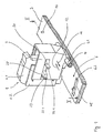
- a first displacement device 6 is provided. This serves for displacing the printhead 1 relative to the printhead mount 2 of FIG a first transverse position in one of the first transverse position transverse to first direction spaced second transverse position. This is the result Print transversely to the first direction of staggered printed images possible.
- the first transfer device 6 is of a first guide device 6.1 and a second guide means 6.2 formed.
- the first guide device consists of a guide 6.1, which at the Bottom of the shell 1.2 is arranged.
- the second guide device consists of a guide pin 6.2, which on the base element. 3 is arranged and can run in the guide 6.1.
- the guide groove 6.1 and the guide pin act 6.2 in the process of printhead mount 2 and thus the Printhead 1 along the first direction with mutual relative movement for moving the printhead transversely to the first direction in FIG following way together.
- the guide groove 6.1 has a gradient inclined to the first direction on. It provides with its side walls a first guide surface 8 available, against which the guide pin 6.2 in the procedure in Direction of the arrow 11 is running.
- the guide pin 6.2 is in the region of the first longitudinal position of the Printhead mount 2 arranged so that the transverse displacement of Printhead 1 immediately after the completion of a print image or can be done before starting a printed image.
- the magnet 28 is connected to the shell 1.2 connected and runs in an offset direction of the print head. 1 extending recess in the printhead mount 2.
- the angle 29 and 30 are disposed on the printhead mount 2 and form, respectively a stop for the magnet 28 to limit printhead movement transverse to the first direction. You have one each Stop surface 29.1 and 30.1 on.
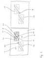
- the printing process has the following sequence in the example shown.
- the right in Fig. 2 by the the contour is 1.5 indicated position.
- the guide 6.1 he will then under procedure offset in the direction of the arrow 11 in its second transverse position.
- he is to create a second print image in the direction of Arrow 12 moved to its second longitudinal position.
- the first and second printed image complement each other to a complete franking expression.
- the printing process is completed.
- the printhead 1 is then placed in its first transverse position and either back in move his parking position or it immediately begins another Frankie output pressure.
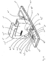
- the print head 1 ' is counteracting each other by means not shown Spring devices relative to the printhead holder 2 'in the absence Action of other devices, such as the locking element etc., in a midway between the first and second transverse position Neutral position held.
- the locking element is of a type at the bottom of the print head 1 'hinged hook-shaped lever 40 formed, the first free end 41 in the second holding device associated groove 39 engages.
- the side surface 39.2 opposite Side surface 39.1 of the groove 39 forms a stop for the lever 40, the transverse movement of the print head 1 'across the limited first direction.
- the lever 40 is biased by a spring 42 to the print head that it is held in its engaged position in the groove 39 and 38, respectively.
- To move the printhead transversely to the first direction must the lever from its engagement with the respective groove 38 , thereby be solved. This happens when moving the printhead mount 2 'along the first direction through the base element 3' arranged Ramps 43 and 44, against which the second free end 45 of the lever 40th running.
- the ramps are arranged so that the lever 40th only from the respective groove 38 or 39 triggers when the respective Guide pin 6.2 'or 14' already in engagement with the respective - not shown - guide groove for moving the print head 1 'of his first transverse position in its second transverse position or of his second transverse position is in its first transverse position. This happens, to make sure that the leader also actually with the respective guide groove engages.
- the transfer device designed so that an offset of the print head transversely to the first Direction is achieved, which is so large that the two at Method of printhead mount between the first and second Longitudinal position and vice versa printed images at best in overlap the edge area, in which they are transverse to the first direction to each other adjoin. Ideally, there is no overlap.
- the both printed images complement each other to a total expression after overlapping transversely to the first direction about twice the dimension has the printed images.
- This guide comprises a pivotally arranged switch 13, by a spring means, not shown, against a stop 13.1 is biased, so that in the normal state, the first Leg 7.1 closes.
- the switch device in other variants
- the device according to the invention also be designed differently can. So it is possible, for example, the switch not as a separate Component, but by an elastically deformable projection or the like in the guide groove to realize.
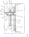
- FIG. 6 shows a partial view of a franking machine with a print head 1 '' 'which is slidably held on a print head holder 2' '.
- the print head 1 '' ' consists of an inkjet cartridge 1.1' '' the replaceable in a shell 1.2 '' 'is mounted.
- the shell is 1.2 "' slidably mounted in the printhead mount 2 "'.
- a first displacement device 6 "' which serves for displacing the print head 1 '' 'relative to the printhead mount 2 "' from a first transverse position to a transverse one from the first transverse position spaced apart from the first direction second transverse position. This is the printing transversely to the first direction of staggered printed images possible.
- the first displacement device 6 '' ' is of a first guide device 6.1 "'and a second guide device 6.2"' first guide means consists of a guide 6.1 '' 'in the Base element 3 "'.
- the second guide device consists of a Guide pin 6.2 "', which is arranged on the underside of the shell 1.2"' is and can run in the guide groove 6.1 "'.
- the guide groove 6.1 '' has a Y-shaped course with a first Leg 7.1 '' 'and a second leg 7.2' 'on, the symmetrical extend to an axis parallel to the first direction. She joins their side walls first guide surfaces 8 "', 9"' and 10 "'to Available, against which the guide pin 6.2 "'as a result of the spring 5 "'applied biasing force is pressed.
- This guide comprises a pivotally arranged switch 13 "', by a spring means, not shown, against the guide surface 8 "'is biased so that they in the normal state first leg 7.1 "'closes.
- the guide groove 5 "' is in the region of the first longitudinal position of the print head holder 2 arranged so that the cross offset of the printhead 1 immediately after the completion of a print image or before the beginning of a printed image can be done.
- the guide groove 14 "' has a guide surface 15"' against which the Guide pin 6.2 “'due to the bias of the spring 5"' pressed becomes. Again, the displacement of the printhead takes place as a result of Inclination of the guide surface 15 "'to the first direction by a method printhead mount 2 "'along the first direction.
- first holding device in the form of a first longitudinal guide groove 16 "'and a second holding device in Form a second longitudinal guide groove 17 "'formed. These are on the Base member 2 "'arranged, wherein they are on the two guide grooves 6.1 “'and 14"' connect. In them, the guide pin can run 6.2 "'.
- the two longitudinal guide grooves 16 '' 'and 17' ' are parallel to first direction. They each have a direction parallel to the first direction Longitudinal guide surface 16.1 '' 'or 17.1' ', against which as a longitudinal guide element acting guide pin 6.2 "'by the bias the spring 5 "'when passing through the respective longitudinal guide groove 16"' or 17 '' 'is pressed.
- the longitudinal guide surfaces 16.1 "'and 17.1' '' form thus each a first stop to limit the printhead movement transverse to the first direction.
- the printing process has the following sequence in the example shown.
- the Printhead is in turning on the postage meter in his Maintenance and parking position, in which the guide pin 6.2 '' 'am End 18 of the Y-shaped guide 6.1 '' 'is located.
- the guide pin 6.2 '''am End 18 of the Y-shaped guide 6.1 '' 'is located At first he will then move in the direction of arrow 12 "'until the print head 1' '' its has reached second transverse position and the first longitudinal position. Then it will be he proceeded further to the second longitudinal position, wherein a first Print image is generated. Afterwards he will continue in the direction of Arrow 12 "'until it reaches the guide groove 14"'.
- Figure 7 shows a plan view of a further alternative design, the in its basic structure is similar to that of Figure 6, so here just to discuss the differences.
- the first holding device further comprises one of a schematic illustrated spring 20 "" spring device formed on the Printhead 1 "” directed away from the guide rod 4 "” force exercises. If the print head 1 "" on the stop surface 19.1 “” of the stop 19 “”, so causes the spring 20 “” a contact force on the stop 19 "”, which holds the print head in its first transverse position.
- the second holding device is in turn of a Lekss adjustmentsnut 21 “" formed as a stop to limit the printhead movement transverse to the first direction parallel to the first direction Longitudinal guide surface 21.1 “” for the at the bottom of the printhead 1 "” arranged guide pin 22 “” forms.
- the spring causes 20 “” a contact force between longitudinal guide surface 21.1 “” and guide pin 22 "", which the print head 1 '' '' in its second transverse position holds.
- FIG. 8 shows a plan view of a further alternative design which in its basic structure similar to that of Figure 6, so that Here too, only the differences should be discussed.
- first and second Holding device differs from a magnet 28 "" and two angles 29 "" 'and 30 ""' made of magnetic metal.
- the magnet 28 '"' is connected to the print head 1 '' '' 'and runs in a in Offset direction of the print head 1 "" 'extending recess in the Printhead mount 2 '' '' '.
- the angles 29 "" 'and 30 ""' are on the printhead mount 2 ''''' 'arranged and each form a stop for the magnet 28 "" 'to limit the printhead movement across the first direction. They each had a stop surface 29.1 "" ' or 30.1 '' '' 'on.
- the angle or a corresponding element may be formed as a magnet and then a corresponding element of a soft magnetic Metal or the like is connected to the print head.
- the guide grooves 31 '"' and 32 ''''' ' are substantially V-shaped. They have in the transition region of their legs a guide 34 '' '' 'and 35' '', respectively, which ensures that the print head 1 '' ' when moving along the first direction from its first transverse position in its second transverse position or from its second transverse position is moved to its first transverse position.
- the guide 34 "" 'or 35 “"' has a start-up area 36 "" 'or 37 ""', which, contrary to the respective direction of offset of the Printhead 1 '' ''' 'is offset from the transverse position, the printhead 1 '' ''' 'in the process along the first direction at the time of Movement reversal of the movement along the first direction has reached. Since the print head 1 "" 'not in the present variant by any spring means or the like against the printhead mount 2 "" 'is biased, it remains in the motion reversal in this transverse position and then runs against the respective start-up area 36 "" 'and 37' '' '', respectively.
Landscapes
- Common Mechanisms (AREA)
Claims (10)
- Dispositif d'impression, en particulier une machine à affranchir, muni d'une tête d'impression (1 ; 1') maintenue de manière déplaçable sur un support de tête d'impression (2 ; 2'), conçu de manière à être mobile pour réaliser le mouvement relatif entre la tête d'impression (1 ; 1') et le médium à imprimer, lors de l'impression, le long d'une première direction relative à un élément de base (3 ; 3') entre une première position longitudinale et une deuxième position longitudinale, un premier mécanisme de déplacement (6.1 ; 6.2 ; 6.1 ") qui permet l'impression d'imprimés décalés les uns par rapport aux autres étant prévu, ledit mécanisme étant conçu transversalement par rapport à la première direction, et ce dans le but de déplacer la tête d'impression (1 ; 1') par rapport au support de tête d'impression (2 ; 2') d'une première position transversale dans au moins une deuxième position transversale espacée de la première position transversale de manière transversale par rapport à la première direction, le premier mécanisme de déplacement comprenant au moins un premier organe de guidage (6.1 ; 6.1') avec une première surface de guidage (8, 9, 10, 8", 9", 10") et au moins un deuxième organe de guidage avec un élément de guidage (6.2), agissant ensemble dans un mouvement relatif mutuel pour le déplacement de la tête d'impression (1 ; 1') de la première à la deuxième position transversale via l'action du support de tête d'impression (2 ; 2') le long de la première direction , caractérisé en ce que l'élément de guidage (6.2) du deuxième organe de guidage est disposé sur l'élément de base (3 ; 3').
- Dispositif selon la revendication 1 caractérisé en ce que le premier organe de guidage est formé par une rainure de guidage (6.1 ; 6.1") et en ce que le deuxième organe de guidage est formé par une tige de guidage (6.2).
- Dispositif selon la revendication 2 caractérisé en ce que la tige de guidage (6.2) comporte une surface effective en forme de cylindre circulaire.
- Dispositif selon l'une quelconque des revendications précédentes caractérisé en ce que le deuxième organe de guidage (6.2) est disposé sur l'élément de base (3) en position mobile et de manière transversale par rapport à la première direction
- Dispositif selon la revendication 4 caractérisé en ce que le deuxième organe de guidage (6.2) est conçu pour le déplacement de position à la manière d'un excentrique.
- Dispositif selon l'une quelconque des revendications précédentes caractérisé en ce que le organe de guidage (6.2) du premier mécanisme de déplacement (6.1, 6.2, 6.1") disposé au niveau de l'élément de base (3 ; 3') est placé dans la zone de la première ou de la deuxième position longitudinale du support de tête d'impression (2 ; 2').
- Dispositif selon l'une quelconque des revendications précédentes caractérisé en ce qu'au moins un deuxième mécanisme de déplacement (14, 6.3) est prévu pour le déplacement de la tête d'impression (1) de la deuxième à la première position transversale.
- Dispositif selon la revendication 7 caractérisé en ce que le deuxième mécanisme de déplacement (14, 6.3) est conçu pour le déplacement de la tête d'impression (1) de la deuxième à la première position transversale par l'action du support de tête d'impression (2) le long de la première direction.
- Dispositif selon la revendication 8 caractérisé en ce que le deuxième mécanisme de déplacement comprend au moins un troisième organe de guidage (14).
- Dispositif selon la revendication 9 caractérisé en ce que le troisième organe de guidage est conçu pour coopérer ensemble avec le premier organe de guidage du premier mécanisme de déplacement.
Applications Claiming Priority (2)
| Application Number | Priority Date | Filing Date | Title |
|---|---|---|---|
| DE10009801A DE10009801A1 (de) | 2000-02-24 | 2000-02-24 | Druckvorrichtung und Druckverfahren mit Querführung zum Versetzen des Druckkopfs quer zur Druckrichtung |
| DE10009801 | 2000-02-24 |
Publications (3)
| Publication Number | Publication Date |
|---|---|
| EP1127701A1 EP1127701A1 (fr) | 2001-08-29 |
| EP1127701B1 true EP1127701B1 (fr) | 2005-12-14 |
| EP1127701B8 EP1127701B8 (fr) | 2006-03-08 |
Family
ID=7632992
Family Applications (1)
| Application Number | Title | Priority Date | Filing Date |
|---|---|---|---|
| EP01250046A Expired - Lifetime EP1127701B8 (fr) | 2000-02-24 | 2001-02-09 | Dispositif d'impression à guidage transversal pour déplacer la tête d'impression perpendiculairement au sens de balayage |
Country Status (3)
| Country | Link |
|---|---|
| US (1) | US6623189B2 (fr) |
| EP (1) | EP1127701B8 (fr) |
| DE (2) | DE10009801A1 (fr) |
Cited By (3)
| Publication number | Priority date | Publication date | Assignee | Title |
|---|---|---|---|---|
| DE202014102699U1 (de) | 2014-06-11 | 2014-06-24 | Francotyp-Postalia Gmbh | Druckergerät |
| DE202014102697U1 (de) | 2014-06-11 | 2014-06-24 | Francotyp-Postalia Gmbh | Druckergerät |
| DE102014103987A1 (de) | 2014-03-24 | 2015-09-24 | Francotyp-Postalia Gmbh | Druckergerät |
Families Citing this family (7)
| Publication number | Priority date | Publication date | Assignee | Title |
|---|---|---|---|---|
| US20030160840A1 (en) * | 2001-10-19 | 2003-08-28 | Haseeb Yusef | Carriage guide for inkjet printer |
| US8192098B1 (en) | 2008-06-17 | 2012-06-05 | Stalsen LLC | Automatically loading printing device and method of printing |
| JP6508720B2 (ja) * | 2015-08-31 | 2019-05-08 | セイコーソリューションズ株式会社 | 印字ユニット及びプリンタ |
| JP6694337B2 (ja) * | 2016-06-22 | 2020-05-13 | セイコーソリューションズ株式会社 | 印字ユニット及びプリンタ |
| US10940698B2 (en) | 2019-02-22 | 2021-03-09 | Xyrec Ip B.V. | System and method for high accuracy printing on a 3D surface |
| DE102019209040B4 (de) * | 2019-06-21 | 2024-11-21 | Volkswagen Aktiengesellschaft | Versorgungssystem und Versorgungsverfahren zum Versorgen eines Fahrzeugs mit elektrischer Energie |
| CN114474300B (zh) * | 2022-02-23 | 2023-11-14 | 北京市市政二建设工程有限责任公司 | 一种混凝土现场3d打印设备及其使用方法 |
Family Cites Families (15)
| Publication number | Priority date | Publication date | Assignee | Title |
|---|---|---|---|---|
| US2651400A (en) * | 1950-08-10 | 1953-09-08 | Don W Young | Graph plotting machine |
| US3583540A (en) * | 1968-05-10 | 1971-06-08 | Honeywell Inc | X{14 y web translating apparatus |
| DE3125426A1 (de) * | 1981-06-27 | 1983-01-20 | Olympia Werke Ag, 2940 Wilhelmshaven | Matrixdrucker mit einem laengs eines aufzeichnungstraegers in druckzeilenrichtung bewegbaren druckkopf |
| JPS60161176A (ja) * | 1984-01-31 | 1985-08-22 | Nec Home Electronics Ltd | 横印字型プリンタ |
| KR960003354B1 (ko) * | 1986-04-24 | 1996-03-08 | 타우러스 임프레션스 인코오포레이티드 | 책자표지 스탬프 프린터 |
| US4774529A (en) * | 1987-02-26 | 1988-09-27 | Xerox Corporation | Repositionable marking head for increasing printing speed |
| DE4237275C1 (de) * | 1992-11-05 | 1993-11-04 | Dorothea Wolf | Stempel |
| US5598192A (en) * | 1995-06-08 | 1997-01-28 | Xerox Corporation | Thermal ink jet printhead with extended print capability |
| US5762428A (en) * | 1995-12-27 | 1998-06-09 | Pitney Bowes Inc. | Method and apparatus for securely printing a postal indicia image by dividing printing of the image in multiple passes |
| JP3752800B2 (ja) * | 1997-10-03 | 2006-03-08 | リコープリンティングシステムズ株式会社 | 記録装置における記録媒体の固定装置 |
| GB9802127D0 (en) * | 1998-01-30 | 1998-04-01 | Neopost Ltd | Method of alignment of imprints |
| DE19822423C2 (de) * | 1998-05-19 | 2001-08-16 | Ernst Reiner Gmbh & Co Kg Fein | Druckgerät für den Druck von wenigstens zwei Zeilen |
| GB9818025D0 (en) * | 1998-08-18 | 1998-10-14 | Neopost Ltd | Print head transport mechanism |
| GB9818026D0 (en) * | 1998-08-18 | 1998-10-14 | Neopost Ltd | Print head transport mechanism |
| GB9902054D0 (en) * | 1999-01-29 | 1999-03-24 | Neopost Ltd | Ink jet printing mechanism |
-
2000
- 2000-02-24 DE DE10009801A patent/DE10009801A1/de not_active Ceased
-
2001
- 2001-02-09 EP EP01250046A patent/EP1127701B8/fr not_active Expired - Lifetime
- 2001-02-09 DE DE50108351T patent/DE50108351D1/de not_active Expired - Lifetime
- 2001-02-26 US US09/793,413 patent/US6623189B2/en not_active Expired - Lifetime
Cited By (4)
| Publication number | Priority date | Publication date | Assignee | Title |
|---|---|---|---|---|
| DE102014103987A1 (de) | 2014-03-24 | 2015-09-24 | Francotyp-Postalia Gmbh | Druckergerät |
| EP2923840A2 (fr) | 2014-03-24 | 2015-09-30 | Francotyp-Postalia GmbH | Imprimante |
| DE202014102699U1 (de) | 2014-06-11 | 2014-06-24 | Francotyp-Postalia Gmbh | Druckergerät |
| DE202014102697U1 (de) | 2014-06-11 | 2014-06-24 | Francotyp-Postalia Gmbh | Druckergerät |
Also Published As
| Publication number | Publication date |
|---|---|
| DE50108351D1 (de) | 2006-01-19 |
| DE10009801A1 (de) | 2001-08-30 |
| US20010053302A1 (en) | 2001-12-20 |
| US6623189B2 (en) | 2003-09-23 |
| EP1127701B8 (fr) | 2006-03-08 |
| EP1127701A1 (fr) | 2001-08-29 |
Similar Documents
| Publication | Publication Date | Title |
|---|---|---|
| DE3301797C2 (fr) | ||
| EP1127701B1 (fr) | Dispositif d'impression à guidage transversal pour déplacer la tête d'impression perpendiculairement au sens de balayage | |
| DE69927889T2 (de) | Transport-Mechanismus eines Druckkopfes | |
| WO1998057832A1 (fr) | Dispositif de reglage de tirant a cable | |
| EP1127702B1 (fr) | Dispositif pour guider une tête d'impression | |
| DE2449913C2 (de) | Skisicherheitsbindung | |
| DE2552837B2 (de) | Druckvorrichtung | |
| AT398885B (de) | Einrichtung zur verstellung der vorlage des schaftes eines schischuhes | |
| DE602005004666T2 (de) | Fahrtrichtungsanzeiger für Kraftfahrzeuge | |
| DE2723578A1 (de) | Vorrichtung zum geradlinigen verschieben eines bauelementes | |
| EP1127700B1 (fr) | Dispositif et méthode d'impression avec guidage mobile pour tête d'impression | |
| DE3112809C2 (fr) | ||
| DE202014102699U1 (de) | Druckergerät | |
| DE2235394C2 (de) | Gliederdruckerkassette | |
| DE1561212B2 (de) | Typenhebelbewegungsvorrichtung fuer kraftangetriebene schreibmaschinen | |
| DE2149094A1 (de) | Vorrichtung zum ausgleich der anschlagkraft an kraftangetriebenen schreibmaschinen | |
| DE8112747U1 (de) | Montage- und einstellvorrichtung fuer einen fahrzeugbremslichtschalter | |
| DE2323893A1 (de) | Kreiselgeraet | |
| DD153774A5 (de) | Vorrichtung zur anschlagregelung fuer den typentraeger einer schreibmaschine,eines fernschreibers oder dergleichen | |
| DE324212C (de) | Papierwagenschaltvorrichtung fuer Schreibmaschinen | |
| DE2545373B1 (de) | Vorrichtung zum veraendern der anschlagstaerke eines typenkopfes in kraftangetriebenen schreibmaschinen | |
| DE3405714C2 (fr) | ||
| DE4123280C2 (de) | Gurtverschluß für einen Sicherheitsgurt eines Kraftfahrzeuges | |
| DE2632370C2 (de) | Betätigungseinrichtung für Objektivgehäuse einer Kamera | |
| DE2603932C3 (de) | Vorrichtung zum Justieren der Anschlagstärke der Typen bei kraftangetriebenen Schreib- o.a. Büromaschinen |
Legal Events
| Date | Code | Title | Description |
|---|---|---|---|
| PUAI | Public reference made under article 153(3) epc to a published international application that has entered the european phase |
Free format text: ORIGINAL CODE: 0009012 |
|
| AK | Designated contracting states |
Kind code of ref document: A1 Designated state(s): AT BE CH CY DE DK ES FI FR GB GR IE IT LI LU MC NL PT SE TR |
|
| AX | Request for extension of the european patent |
Free format text: AL;LT;LV;MK;RO;SI |
|
| 17P | Request for examination filed |
Effective date: 20020123 |
|
| AKX | Designation fees paid |
Free format text: CH DE FR GB IT LI |
|
| RAP1 | Party data changed (applicant data changed or rights of an application transferred) |
Owner name: FRANCOTYP-POSTALIA AG & CO. KG |
|
| GRAP | Despatch of communication of intention to grant a patent |
Free format text: ORIGINAL CODE: EPIDOSNIGR1 |
|
| GRAS | Grant fee paid |
Free format text: ORIGINAL CODE: EPIDOSNIGR3 |
|
| GRAA | (expected) grant |
Free format text: ORIGINAL CODE: 0009210 |
|
| AK | Designated contracting states |
Kind code of ref document: B1 Designated state(s): CH DE FR GB IT LI |
|
| REG | Reference to a national code |
Ref country code: GB Ref legal event code: FG4D Free format text: NOT ENGLISH |
|
| REG | Reference to a national code |
Ref country code: CH Ref legal event code: EP |
|
| REG | Reference to a national code |
Ref country code: CH Ref legal event code: NV Representative=s name: ROTTMANN, ZIMMERMANN + PARTNER AG |
|
| RAP2 | Party data changed (patent owner data changed or rights of a patent transferred) |
Owner name: FRANCOTYP-POSTALIA GMBH |
|
| REF | Corresponds to: |
Ref document number: 50108351 Country of ref document: DE Date of ref document: 20060119 Kind code of ref document: P |
|
| GBT | Gb: translation of ep patent filed (gb section 77(6)(a)/1977) |
Effective date: 20060227 |
|
| ET | Fr: translation filed | ||
| PLBE | No opposition filed within time limit |
Free format text: ORIGINAL CODE: 0009261 |
|
| STAA | Information on the status of an ep patent application or granted ep patent |
Free format text: STATUS: NO OPPOSITION FILED WITHIN TIME LIMIT |
|
| 26N | No opposition filed |
Effective date: 20060915 |
|
| PGRI | Patent reinstated in contracting state [announced from national office to epo] |
Ref country code: IT Effective date: 20090601 |
|
| REG | Reference to a national code |
Ref country code: CH Ref legal event code: PFA Owner name: FRANCOTYP-POSTALIA GMBH Free format text: FRANCOTYP-POSTALIA GMBH#TRIFTWEG 21-26#16547 BIRKENWERDER (DE) -TRANSFER TO- FRANCOTYP-POSTALIA GMBH#TRIFTWEG 21-26#16547 BIRKENWERDER (DE) |
|
| REG | Reference to a national code |
Ref country code: DE Ref legal event code: R084 Ref document number: 50108351 Country of ref document: DE Effective date: 20130124 |
|
| REG | Reference to a national code |
Ref country code: GB Ref legal event code: 746 Effective date: 20130319 |
|
| REG | Reference to a national code |
Ref country code: GB Ref legal event code: 732E Free format text: REGISTERED BETWEEN 20130502 AND 20130508 |
|
| REG | Reference to a national code |
Ref country code: FR Ref legal event code: PLFP Year of fee payment: 15 |
|
| PGFP | Annual fee paid to national office [announced via postgrant information from national office to epo] |
Ref country code: DE Payment date: 20150112 Year of fee payment: 15 Ref country code: CH Payment date: 20150218 Year of fee payment: 15 Ref country code: IT Payment date: 20150226 Year of fee payment: 15 |
|
| PGFP | Annual fee paid to national office [announced via postgrant information from national office to epo] |
Ref country code: FR Payment date: 20150219 Year of fee payment: 15 Ref country code: GB Payment date: 20150218 Year of fee payment: 15 |
|
| REG | Reference to a national code |
Ref country code: DE Ref legal event code: R119 Ref document number: 50108351 Country of ref document: DE |
|
| REG | Reference to a national code |
Ref country code: CH Ref legal event code: PL |
|
| GBPC | Gb: european patent ceased through non-payment of renewal fee |
Effective date: 20160209 |
|
| PG25 | Lapsed in a contracting state [announced via postgrant information from national office to epo] |
Ref country code: LI Free format text: LAPSE BECAUSE OF NON-PAYMENT OF DUE FEES Effective date: 20160229 Ref country code: CH Free format text: LAPSE BECAUSE OF NON-PAYMENT OF DUE FEES Effective date: 20160229 |
|
| REG | Reference to a national code |
Ref country code: FR Ref legal event code: ST Effective date: 20161028 |
|
| PG25 | Lapsed in a contracting state [announced via postgrant information from national office to epo] |
Ref country code: IT Free format text: LAPSE BECAUSE OF NON-PAYMENT OF DUE FEES Effective date: 20160209 |
|
| PG25 | Lapsed in a contracting state [announced via postgrant information from national office to epo] |
Ref country code: DE Free format text: LAPSE BECAUSE OF NON-PAYMENT OF DUE FEES Effective date: 20160901 Ref country code: FR Free format text: LAPSE BECAUSE OF NON-PAYMENT OF DUE FEES Effective date: 20160229 Ref country code: GB Free format text: LAPSE BECAUSE OF NON-PAYMENT OF DUE FEES Effective date: 20160209 |