EP1127724A1 - Method for overcoming partial stiffness of movable plates - Google Patents
Method for overcoming partial stiffness of movable plates Download PDFInfo
- Publication number
- EP1127724A1 EP1127724A1 EP01102206A EP01102206A EP1127724A1 EP 1127724 A1 EP1127724 A1 EP 1127724A1 EP 01102206 A EP01102206 A EP 01102206A EP 01102206 A EP01102206 A EP 01102206A EP 1127724 A1 EP1127724 A1 EP 1127724A1
- Authority
- EP
- European Patent Office
- Prior art keywords
- force
- automatic
- electric drive
- routine
- stiffness
- Prior art date
- Legal status (The legal status is an assumption and is not a legal conclusion. Google has not performed a legal analysis and makes no representation as to the accuracy of the status listed.)
- Granted
Links
- 238000000034 method Methods 0.000 title claims abstract description 14
- 230000006870 function Effects 0.000 claims description 22
- 238000012544 monitoring process Methods 0.000 claims description 9
- 230000003044 adaptive effect Effects 0.000 claims description 3
- 238000010586 diagram Methods 0.000 description 6
- 230000006978 adaptation Effects 0.000 description 2
- 230000001960 triggered effect Effects 0.000 description 2
- 238000001514 detection method Methods 0.000 description 1
- 238000006073 displacement reaction Methods 0.000 description 1
- 230000007704 transition Effects 0.000 description 1
- 238000011144 upstream manufacturing Methods 0.000 description 1
Images

Classifications
-
- B—PERFORMING OPERATIONS; TRANSPORTING
- B60—VEHICLES IN GENERAL
- B60J—WINDOWS, WINDSCREENS, NON-FIXED ROOFS, DOORS, OR SIMILAR DEVICES FOR VEHICLES; REMOVABLE EXTERNAL PROTECTIVE COVERINGS SPECIALLY ADAPTED FOR VEHICLES
- B60J7/00—Non-fixed roofs; Roofs with movable panels, e.g. rotary sunroofs
- B60J7/02—Non-fixed roofs; Roofs with movable panels, e.g. rotary sunroofs of sliding type, e.g. comprising guide shoes
- B60J7/04—Non-fixed roofs; Roofs with movable panels, e.g. rotary sunroofs of sliding type, e.g. comprising guide shoes with rigid plate-like element or elements, e.g. open roofs with harmonica-type folding rigid panels
- B60J7/057—Driving or actuating arrangements e.g. manually operated levers or knobs
- B60J7/0573—Driving or actuating arrangements e.g. manually operated levers or knobs power driven arrangements, e.g. electrical
-
- E—FIXED CONSTRUCTIONS
- E05—LOCKS; KEYS; WINDOW OR DOOR FITTINGS; SAFES
- E05F—DEVICES FOR MOVING WINGS INTO OPEN OR CLOSED POSITION; CHECKS FOR WINGS; WING FITTINGS NOT OTHERWISE PROVIDED FOR, CONCERNED WITH THE FUNCTIONING OF THE WING
- E05F15/00—Power-operated mechanisms for wings
- E05F15/60—Power-operated mechanisms for wings using electrical actuators
- E05F15/603—Power-operated mechanisms for wings using electrical actuators using rotary electromotors
- E05F15/665—Power-operated mechanisms for wings using electrical actuators using rotary electromotors for vertically-sliding wings
- E05F15/689—Power-operated mechanisms for wings using electrical actuators using rotary electromotors for vertically-sliding wings specially adapted for vehicle windows
- E05F15/695—Control circuits therefor
-
- E—FIXED CONSTRUCTIONS
- E05—LOCKS; KEYS; WINDOW OR DOOR FITTINGS; SAFES
- E05Y—INDEXING SCHEME ASSOCIATED WITH SUBCLASSES E05D AND E05F, RELATING TO CONSTRUCTION ELEMENTS, ELECTRIC CONTROL, POWER SUPPLY, POWER SIGNAL OR TRANSMISSION, USER INTERFACES, MOUNTING OR COUPLING, DETAILS, ACCESSORIES, AUXILIARY OPERATIONS NOT OTHERWISE PROVIDED FOR, APPLICATION THEREOF
- E05Y2900/00—Application of doors, windows, wings or fittings thereof
- E05Y2900/50—Application of doors, windows, wings or fittings thereof for vehicles
- E05Y2900/53—Type of wing
- E05Y2900/542—Roof panels
-
- E—FIXED CONSTRUCTIONS
- E05—LOCKS; KEYS; WINDOW OR DOOR FITTINGS; SAFES
- E05Y—INDEXING SCHEME ASSOCIATED WITH SUBCLASSES E05D AND E05F, RELATING TO CONSTRUCTION ELEMENTS, ELECTRIC CONTROL, POWER SUPPLY, POWER SIGNAL OR TRANSMISSION, USER INTERFACES, MOUNTING OR COUPLING, DETAILS, ACCESSORIES, AUXILIARY OPERATIONS NOT OTHERWISE PROVIDED FOR, APPLICATION THEREOF
- E05Y2900/00—Application of doors, windows, wings or fittings thereof
- E05Y2900/50—Application of doors, windows, wings or fittings thereof for vehicles
- E05Y2900/53—Type of wing
- E05Y2900/55—Windows
-
- G—PHYSICS
- G05—CONTROLLING; REGULATING
- G05B—CONTROL OR REGULATING SYSTEMS IN GENERAL; FUNCTIONAL ELEMENTS OF SUCH SYSTEMS; MONITORING OR TESTING ARRANGEMENTS FOR SUCH SYSTEMS OR ELEMENTS
- G05B2219/00—Program-control systems
- G05B2219/30—Nc systems
- G05B2219/42—Servomotor, servo controller kind till VSS
- G05B2219/42272—Total movement is divided in several zones with different protection parameters
Definitions
- the invention relates to a method for partial monitoring Stiffness on movable surfaces, such as window panes or sunroofs.
- movable surfaces such as window panes or sunroofs.
- These components provided in the motor vehicle are in increasingly equipped with electric drives, one Allow remote control of these areas.
- Stiffness occurs when For example, wind deflectors arranged upstream from sunroofs when the Driving speed are subject to increased air resistance and in this Situation an actuation of a sunroof takes place.
- electric drives for actuating Window surfaces or sunroofs were manual bridging functions provided with which driven at a point of stiffness movable surfaces were moved by hand over the stiffness point. Manual intervention by the operator directs the operator when operating one Motor vehicle and can lead to critical driving situations in which the Driver cannot give his undivided attention to traffic.
- reference runs burden the electric drive unnecessarily as it is only a calibration function to have. Reference runs are also time consuming and during the Reference runs are far from all the conditions that arise later in operation the window panes or sunroofs can occur.
- an automatic Bypass function applied to adjust the speed curve.
- the automatic control ensures that only in the narrow limited area of the transition point identified as such which Release force is increased by a certain amount. If a one time Increasing the trigger power by a certain amount is not sufficient to To overcome the stiffness point, the automatic Bridging function step by step in several start-up routines up to one Maximum value increased. Is with a below the maximum release force lying trigger force overcoming the stiffness takes place, so the release force required to overcome the obstacle in one adaptive storage unit can be stored.
- the maximum value of the release force can be preset on the automatic bypass function so that Depending on the application, certain maximum triggering forces are provided or can be approved. Also the increments with which the release force can be raised gradually within the startup routine, can be variable at the automatic bypass function can be selected.
- the gradual increase in the triggering force can, for example, in one first drive onto an obstacle and then reverse the drive embed. If the obstacle is outside the area in which the The point of binding is localized, the drive reverses; lies the Binding point within the path window, the trigger force is only for the area where the binding point is located. After multiple Approach and impact on the obstacle is gradual Increase the release force in the area of the travel window until the maximum specified trigger force is reached.
- the obstacle representing the binding point will be without Reversing the electric drive can be overcome Adapt the speed adaptation to the changed conditions, the obstacle just overcoming trigger force, or the speed adaptation in one Memory that is assigned to the automatic bridging function is stored become.
- FIG. 1 shows both that which arises Drop in speed on the electric drive, as well as through the passage of one Stiffness range 4.1 triggered trigger force increase.
- the speed / displacement diagram contained in FIG. 1 is the speed curve 1 plotted over path 2.
- the stiffness area to be overcome 4.1 there is a drop in speed; not in a discrete place of the Travel path 2, but extending over a travel path area 4.1.
- the force that is required to overcome the stiffness range 4.1 gradually increased until the driven surface to be moved, for example a window pane or a sliding roof smooth the area of difficulty 4.1 happen without the electric drive reversing.
- the triggering force 3 is over the path 2 plotted, the one shown in the upper diagram of FIG. 1 Binding range 4.1 is transferred to the lower diagram.
- the automatic bypass function Stiffness range 4.1 there is a gradual increase in Release force, then restarting the stiffness area 4.1 with increased release force.
- the increase in the release force is limited in the set maximum permissible value of the trigger force, which at the automatic bridging function is specified.
- the maximum value for the Tripping force is in the lower diagram according to FIG. 1 with reference number 9 identified.
- the Run through start-up routines 15, 19 see FIG. 2) until n is necessary Tripping force increasing steps are processed.
- In an adaptive Storage system can be the predetermined trigger force value 5 by that Overwrite the value for the release force that is currently traversing the surface can overcome the binding area 4.1.
- the speed of an electric drive can be partial Difficulties, such as those with wind deflectors Sunroofs can occur, adjust.
- the actual circumstances Adapted speed values can be stored in the storage system.
- a first Pinch query 13 is run. Is this state the one to be traversed? Detected area, the position of the stiffness area 4.1 is saved, the timer is set and the electric drive reverses. This is done by the pinch parameter memory 14, from which in the in the state machine 10 also contains monitoring module 12 is branched. There will brought about a first increase in clamping force 16, which is then triggered of the electric drive within the first startup routine 15 onto the surface is transmitted. It is monitored whether within the first startup routine 15 the Electric drive run is terminated normally, or whether a new one Pinching situation has occurred. If the engine run ends normally, the Increasing the clamping force at position 16 in the monitoring module was taken back again.
- the run is within the first startup routine 15 to be run of the electric drive has not ended normally, is a new one Pinching situation occurred.
- the renewed pinching situation is indicated by a repeated query 19 verified within the monitoring module 12; the second pinch query 17 with a positive result causes a new one Clamping force increase at position 18, so that now after unsuccessful Execution of the first start-up routine 15 with the second start-up routine 19 increased value for the clamping force to be applied can be run through.
- the shape is checked 21 as to whether the electric drive is running has ended normally, or if there is another pinching situation. Thereafter, the repeated increase in clamping force 18 is withdrawn before is branched to the start or destination point 11.
- the Monitoring module 12 In addition to the two start-up routines 15, 19, which have different heights The trigger forces can be monitored, the Monitoring module 12, for example, whether a previously set Engine downtime of 10 seconds, for example, is exceeded or not. If so, the system also branches to the start or destination query point 11 and the automatic bypass function is reset. A reset of the automatic bridging function also occurs when the query 25 the control of the electric drive a reversal of direction on electric drive has occurred. If a reversal of rotation occurs moves the approaching surface - be it a window pane or a sunroof - into their open position back. Also in the closed position of each moving surface is the automatic bridging function 10 reset.
- a sequence of the automatic bypass function according to the diagram 2 is roughly as follows:
- the reverses electric drive by means of the automatic bridging function an increase in the release force, which is, for example, as F> 100 N.
- an increase in the release force which is, for example, as F> 100 N.
- the surface to be traversed is restarted in the Difficulty when running through the first startup routine 15. It comes again to a pinching situation, is carried out by running through the second Startup routine 19 a second start with a gradual increase in Release force to the obstacle, representing the binding area 4.1 overcome.
- These attempts are made with a gradual increase in Release force until the gradually increased release force predeterminable maximum value of the trigger force 9 (see FIG. 1) assumes. Can The obstacle will eventually be overcome, the trigger force stored and assigned to that path area 4.1 on which the Stability range 4.1 has found.
- Adapted force threshold to be overcome for the release force adjust so that the electric drive that drives the surface to be moved speed and release force is adapted to the stiffness range 4.1 and the route sections 2 to be covered with predetermined ones Trigger force 5 passes through and upon detection of the previously stored Stability range 4.1 of the electric drive with a step increased Tripping force is operated.
Landscapes
- Engineering & Computer Science (AREA)
- Mechanical Engineering (AREA)
- Power-Operated Mechanisms For Wings (AREA)
- Window Of Vehicle (AREA)
Abstract
Die Erfindung bezieht sich auf ein Verfahren zur Überbrückung partieller
Schwergängigkeiten an verfahrbaren Flächen, wobei diese Flächen in Führungen
aufgenommen sind. Die Flächen werden mittels elektrischer Antriebsmotoren
verfahren, an deren Ansteuerung eine Überlappungsfunktion vorgesehen ist.
Mittels einer automatisch arbeitenden Steuerung (10) wird eine automatische
Überbrückungsfunktion geschaffen, bei der innerhalb eines
Schwergängigkeitsbereiches (4.1) die Auslösekraft in einen oder mehreren
Schritten variiert wird.
Description
Die Erfindung bezieht sich auf ein Verfahren zur Überwachung partieller Schwergängigkeiten an verfahrbaren Flächen, wie beispielsweise Fensterscheiben oder Schiebedächern. Diese im Kraftfahrzeug vorgesehenen Bauteile werden in zunehmenden Maße mit elektrischen Antrieben ausgerüstet, die eine Fernbedienung dieser Flächen gestatten. Schwergängigkeiten treten auf, wenn beispielsweise Schiebedächern vorgeordnete Windabweiser bei Erhöhung der Fahrgeschwindigkeit einem erhöhten Luftwiderstand ausgesetzt sind und in dieser Situation eine Betätigung eines Schiebedaches erfolgt.The invention relates to a method for partial monitoring Stiffness on movable surfaces, such as window panes or sunroofs. These components provided in the motor vehicle are in increasingly equipped with electric drives, one Allow remote control of these areas. Stiffness occurs when For example, wind deflectors arranged upstream from sunroofs when the Driving speed are subject to increased air resistance and in this Situation an actuation of a sunroof takes place.
Bei bisherigen Ausführungsformen elektrischer Antriebe zur Betätigung von Fensterflächen oder Schiebedächern waren manuelle Überbrückungsfunktionen vorgesehen, mit denen an einer Schwergängigkeitsstelle angelangte angetriebene verschiebbare Flächen per Hand über die Schwergängigkeitsstelle bewegt wurden. Ein manueller Eingriff des Bedieners lenkt diesen beim Führen eines Kraftfahrzeuges ab und kann zu kritischen Fahrsituationen führen, in denen der Fahrer dem Verkehr nicht seine ungeteilte Aufmerksamkeit widmen kann. In previous embodiments, electric drives for actuating Window surfaces or sunroofs were manual bridging functions provided with which driven at a point of stiffness movable surfaces were moved by hand over the stiffness point. Manual intervention by the operator directs the operator when operating one Motor vehicle and can lead to critical driving situations in which the Driver cannot give his undivided attention to traffic.
Bei anderen Varianten von Fensterscheiben oder von Schiebedächern bewegenden Systemen sind Referenzläufe vorgesehen. Die Referenzläufe belasten den elektrischen Antrieb unnötigerweise, da sie lediglich eine Kalibrierfunktion haben. Referenzläufe sind darüber hinaus zeitaufwendig und während der Referenzläufe treten längst nicht alle jene Bedingungen ein, die später bei Betrieb der Fensterscheiben bzw. der Schiebedächer auftreten können.In other variants of window panes or moving roofs Systems are provided for reference runs. The reference runs burden the electric drive unnecessarily as it is only a calibration function to have. Reference runs are also time consuming and during the Reference runs are far from all the conditions that arise later in operation the window panes or sunroofs can occur.
Mit der erfindungsgemäßen Lösung wird eine automatische Überbrückungsfunktion angewendet, um den Drehzahlverlauf anzupassen. Die automatisch arbeitende Steuerung sorgt dafür, daß nur in dem schmalen eingegrenzten Bereich der Übergangsstelle, die als solche identifiziert ist, die Auslösekraft um einen gewissen Betrag erhöht wird. Wenn eine einmalige Erhöhung der Auslösekraft um einen bestimmten Betrag nicht ausreichend ist, um die Schwergängigkeitsstelle zu überwinden, wird diese durch die automatische Überbrückungsfunktion schrittweise in mehreren Anlaufroutinen bis zu einem Maximalwert erhöht. Ist mit einer unterhalb der maximalen Auslösekraft liegenden Auslösekraft die Überwindung der Schwergängigkeitsstelle erfolgt, so kann die zur Überwindung des Hindernisses erforderliche Auslösekraft in einer adaptiven Speichereinheit gespeichert werden. Der Maximalwert der Auslösekraft kann an der automatischen Überbrückungsfunktion voreingestellt werden, so daß je nach Anwendungsfall bestimmte maximale Auslösekräfte vorgesehen bzw. zugelassen werden können. Auch die Schrittweiten, mit der sich die Auslösekraft stufenweise innerhalb der Anlaufroutine anheben läßt, kann variabel an der automatischen Überbrückungsfunktion vorgewählt werden.With the solution according to the invention, an automatic Bypass function applied to adjust the speed curve. The automatic control ensures that only in the narrow limited area of the transition point identified as such which Release force is increased by a certain amount. If a one time Increasing the trigger power by a certain amount is not sufficient to To overcome the stiffness point, the automatic Bridging function step by step in several start-up routines up to one Maximum value increased. Is with a below the maximum release force lying trigger force overcoming the stiffness takes place, so the release force required to overcome the obstacle in one adaptive storage unit can be stored. The maximum value of the release force can be preset on the automatic bypass function so that Depending on the application, certain maximum triggering forces are provided or can be approved. Also the increments with which the release force can be raised gradually within the startup routine, can be variable at the automatic bypass function can be selected.
Die stufenweise Erhöhung der Auslösekraft läßt sich beispielsweise in einem ersten Auffahren auf ein Hindernis mit anschließendem Reversieren des Antriebes einbetten. Liegt das Hindernis außerhalb des Bereiches, in dem die Schwergängigkeitsstelle lokalisiert ist, reversiert der Antrieb; liegt die Schwergängigkeitsstelle innerhalb des Wegfensters, wird die Auslösekraft nur für den Bereich, in dem die Schwergängigkeitsstelle liegt, erhöht. Nach mehrfachem Anfahren und Auflaufen auf das Hindernis kommt es zu einer stufenweisen Erhöhung der Auslösekraft im Bereich des Wegfensters, bis die maximal festgelegte Auslösekraft erreicht ist.The gradual increase in the triggering force can, for example, in one first drive onto an obstacle and then reverse the drive embed. If the obstacle is outside the area in which the The point of binding is localized, the drive reverses; lies the Binding point within the path window, the trigger force is only for the area where the binding point is located. After multiple Approach and impact on the obstacle is gradual Increase the release force in the area of the travel window until the maximum specified trigger force is reached.
Wird das die Schwergängigkeitsstelle darstellende Hindernis schließlich ohne Reversieren des elektrischen Antriebes überwunden, kann sich die Drehzahladaption an die geänderten Verhältnisse anpassen, die das Hindernis gerade überwindende Auslösekraft, bzw. die Drehzahladaption kann in einem Speicher, der der automatischen Überbrückungsfunktion zugeordnet ist, abgelegt werden.Finally, the obstacle representing the binding point will be without Reversing the electric drive can be overcome Adapt the speed adaptation to the changed conditions, the obstacle just overcoming trigger force, or the speed adaptation in one Memory that is assigned to the automatic bridging function is stored become.
Anhand der Zeichnung wird die Erfindung nachstehend näher erläutert.The invention is explained in more detail below with the aid of the drawing.
Es zeigt:
- Fig. 1
- den Drehzahlverlauf des elektrischen Antriebes mit einer zu überwindenden Schwergängigkeitsstelle
- Fig. 2
- die Darstellung der Überbrückungsfunktion als Zustandsautomat.
- Fig. 1
- the speed curve of the electric drive with a stiffness to be overcome
- Fig. 2
- the representation of the bridging function as a state machine.
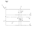
Die Darstellung gemäß Fig. 1 zeigt den Drehzahlverlauf des elektrischen Antriebes mit einer zu überwindenden Schwergängigkeitsstelle. 1 shows the speed curve of the electrical Drive with a stiffness point to be overcome.
Aus der Darstellung gemäß Fig. 1 geht sowohl der sich einstellende
Drehzahleinbruch am elektrischen Antrieb, als auch die durch die Passage eines
Schwergängigkeitsbereiches 4.1 ausgelöste Auslösekrafterhöhung hervor. Im
oberen in Fig. 1 enthaltenen Drehzahl/Wegdiagramm ist der Drehzahlverlauf 1
über dem Weg 2 aufgetragen. Im zu überwindenden Schwergängigkeitsbereich
4.1 tritt ein Drehzahleinbruch auf; nicht an einer diskreten Stelle des
Verfahrweges 2, sondern sich über einen Verfahrwegbereich 4.1 erstreckend.
Mittels der erfindungsgemäß vorgeschlagenen Vorgehensweise wird die Kraft, die
zur Überwindung des Schwergängigkeitsbereiches 4.1 erforderlich ist,
stufenweise gesteigert, bis die angetriebene zu verfahrende Fläche, beispielsweise
eine Fensterscheibe oder ein Schiebedach den Schwergängigkeitsbereich 4.1 glatt
passieren, ohne daß der elektrische Antrieb reversiert.1 shows both that which arises
Drop in speed on the electric drive, as well as through the passage of one
Stiffness range 4.1 triggered trigger force increase. in the
The speed / displacement diagram contained in FIG. 1 is the
Im unteren Diagramm gemäß Fig.1 ist die Auslösekraft 3 über dem Weg 2
aufgetragen, wobei der im oberen Diagramm der Fig. 1 dargestellte
Schwergängigkeitsbereich 4.1 in das untere Diagramm übertragen ist. Innerhalb
des die automatische Überbrückungsfunktion auslösenden
Schwergängigkeitsbereiches 4.1 erfolgt eine stufenweise Erhöhung der
Auslösekraft, danach ein erneutes Anlaufen des Schwergängigkeitsbereiches 4.1
mit erhöhter Auslösekraft. Die Erhöhung der Auslösekraft findet ihre Begrenzung
in dem gesetzten maximal zulässigen Wert der Auslösekraft, der an der
automatischen Überbrückungsfunktion vorgegeben ist. Der maximale Wert für die
Auslösekraft ist im unteren Diagramm gemäß Fig. 1 mit Bezugszeichen 9
identifiziert. Je nach vorgegebenen Auslösekrafterhöhungsschritten werden die
Anlaufroutinen 15, 19 (vergleiche Fig. 2) so oft durchlaufen, bis n notwendige
Auslösekrafterhöhungsschritte abgearbeitet sind. In einem adaptiven
Speichersystem läßt sich der vorgegebene Auslösekraftwert 5 durch denjenigen
Wert für die Auslösekraft überschreiben, der die zu verfahrende Fläche gerade
den Schwergängigkeitsbereich 4.1 überwinden läßt. In the lower diagram according to FIG. 1, the
Die Drehzahl eines elektrischen Antriebes läßt sich so an partielle Schwergängigkeiten, wie sie beispielsweise bei Windabweisern an Schiebedächern auftreten können, anpassen. An die tatsächlichen Gegebenheiten adaptierte Drehzahlwerte lassen sich im Speichersystem ablegen.The speed of an electric drive can be partial Difficulties, such as those with wind deflectors Sunroofs can occur, adjust. The actual circumstances Adapted speed values can be stored in the storage system.
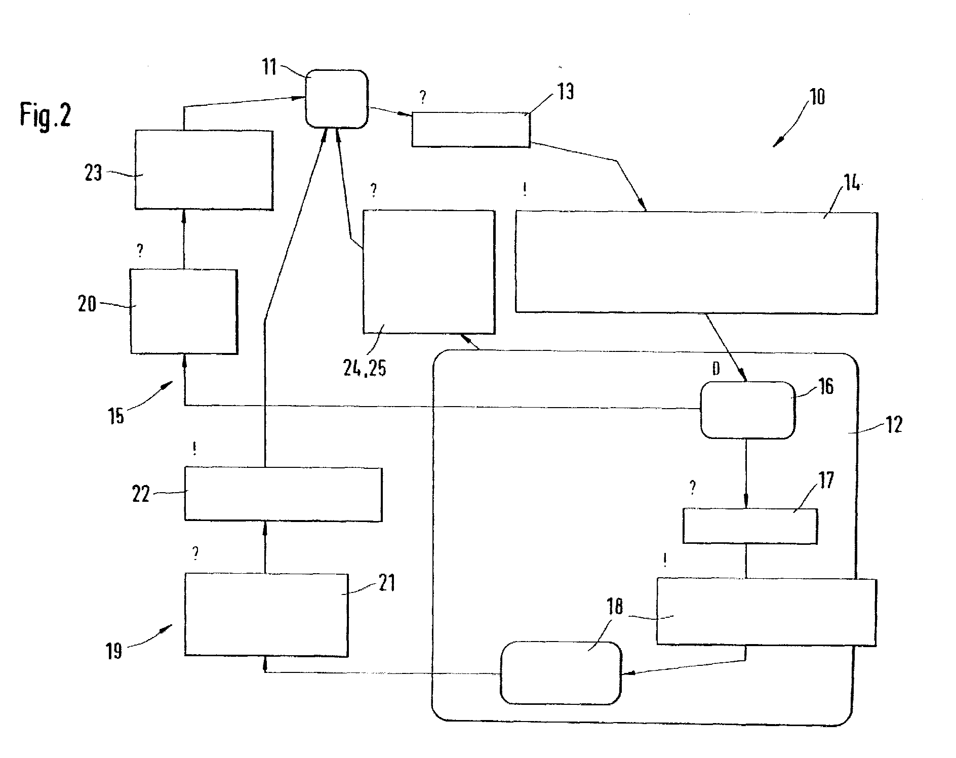
Aus der Darstellung der Überbrückungsfunktion als Zustandsautomat gemäß Fig.
2 geht hervor, wie ausgehend von einem Start und Ziel, bzw. Endpunkt der
Abarbeitung der automatischen Überbrückungsfunktionsroutine eine erste
Einklemmabfrage 13 durchlaufen wird. Ist dieser Zustand der zu verfahrenden
Fläche erkannt, wird die Position des Schwergängigkeitsbereiches 4.1 gespeichert,
der Zeitbegrenzer gesetzt und der elektrische Antrieb reversiert. Dies erfolgt durch
den Einklemmparameterspeicher 14, von dem aus in den im Zustandsautomaten
10 ebenfalls enthaltenden Überwachungsbaustein 12 verzweigt wird. Dort wird
eine erste Klemmkrafterhöhung 16 herbeigeführt, die dann durch die Ansteuerung
des elektrischen Antriebes innerhalb der ersten Anlaufroutine 15 auf die Fläche
übertragen wird. Es wird überwacht, ob innerhalb der ersten Anlaufroutine 15 der
Lauf des elektrischen Antriebes normal beendet wird, oder ob eine neue
Einklemmsituation aufgetreten ist. Wird der Motorlauf normal beendet, wird die
Erhöhung der Klemmkraft, die bei Position 16 im Überwachungsbaustein
vorgenommen wurde, wieder zurückgenommen.From the representation of the bridging function as a state machine according to FIG.
2 shows how, starting from a start and finish, or end point of the
Execution of the automatic bridging function routine a
Ist hingegen innerhalb der ersten zu durchlaufenden Anlaufroutine 15 der Lauf
des elektrischen Antriebes nicht normal beendet worden, ist eine neue
Einklemmsituation aufgetreten. Die erneute Einklemmsituation wird durch eine
nochmalige Abfrage 19 innerhalb des Überwachungsbausteines 12 verifiziert; die
zweite Einklemmabfrage 17 mit positivem Resultat bewirkt eine nochmalige
Klemmkrafterhöhung bei Position 18, so daß nunmehr nach erfolgloser
Abarbeitung der ersten Anlaufroutine 15 die zweite Anlaufroutine 19 mit
erhöhtem Wert für die aufzubringende Klemmkraft durchlaufen werden kann.
Nach Erhöhung der Auslösekraft und Durchlaufen der zweiten Anlaufroutine 19
erfolgt eine Abprüfung 21 der Gestalt, ob der elektrische Antrieb seinen Lauf
normal beendet hat, oder ob es erneut zu einer Einklemmsituation gekommen ist.
Danach wird die nochmalige Klemmkrafterhöhung 18 zurückgenommen, bevor
zum Start- bzw. Zielpunkt 11 verzweigt wird.On the other hand, the run is within the
Neben den beiden Anlaufroutinen 15, 19, die mit unterschiedlich hohen
Auslösekräften durchlaufen werden können, überwacht der
Überwachungsbaustein 12, ob beispielsweise eine zuvor gesetzte
Motorstillstandszeit von beispielsweise 10 Sekunden überschritten ist oder nicht.
Ist dem so, wird ebenfalls an den Start- bzw. Zielabfragepunkt 11 verzweigt und
die automatische Überbrückungsfunktion zurückgesetzt. Ein Zurücksetzen der
automatischen Überbrückungsfunktion erfolgt ferner dann, wenn bei der Abfrage
25 der Ansteuerung des elektrischen Antriebes eine Drehrichtungsumkehr am
elektrischen Antrieb aufgetreten ist. Bei Auftreten einer Verdrehrichtungsumkehr
fährt die zufahrende Fläche - sei es eine Fensterscheibe oder ein Schiebedach - in
ihre geöffnete Position zurück. Auch in der geschlossenen Position der jeweils zu
verfahrenden Fläche ist die automatische Überbrückungsfunktion 10
zurückgesetzt.In addition to the two start-
Ein Ablauf der automatischen Überbrückungsfunktion gemäß des Diagramms nach Fig. 2 stellt sich etwa wie folgt dar:A sequence of the automatic bypass function according to the diagram 2 is roughly as follows:
Es erfolgt zunächst ein erstes Anfahren auf ein eine Schwergängigkeit erzeugendes Hindernis. Der die zu verfahrende Fläche antreibende elektrische Antrieb reversiert und fährt die Fläche aus dem Schwergängigkeitsbereich heraus, falls das Hindernis außerhalb des Schwergängigkeitsbereiches 4.1 liegen sollte.First there is a first approach to a stiffness creating obstacle. The electric driving the surface to be moved Drive reverses and moves the surface out of the stiff area, if the obstacle is outside the stiffness range 4.1.
Liegt das Hindernis innerhalb des Schwergängigkeitsbereiches 4.1, reversiert der
elektrische Antrieb; mittels der automatischen Überbrückungsfunktion erfolgt
eine Steigerung der Auslösekraft, die beispielsweise als F > 100 N liegt. Danach
erfolgt ein erneuter Anlauf der zu verfahrenden Fläche in den
Schwergängigkeitsbereich beim Durchlauf der ersten Anlaufroutine 15. Kommt es
erneut zu einer Einklemmsituation, erfolgt durch Durchlauf der zweiten
Anlaufroutine 19 ein zweiter Anlauf mit einer gestuften Erhöhung der
Auslösekraft, um das Hindernis, den Schwergängigkeitsbereich 4.1 darstellend, zu
überwinden. Diese Anläufe erfolgen mit jeweils gestufter Erhöhung der
Auslösekraft so lange, bis die stufenweise gesteigerte Auslösekraft den
vorgebbaren Maximalwert der Auslösekraft 9 (vergleiche Fig. 1) annimmt. Kann
das Hindernis schließlich überwunden werden, wird die Auslösekraft
abgespeichert und demjenigen Wegbereich 4.1 zugeordnet, an der sich der
Schwergängigkeitsbereich 4.1 befunden hat. Auf diese Weise läßt sich ein an die
zu überwindende Verfahrstrecke angepaßte Kraftschwelle für die Auslösekraft
einstellen, so daß der die zu verfahrende Fläche antreibende elektrische Antrieb
drehzahl und auslösekraftmäßig an den Schwergängigkeitsbereich 4.1 angepaßt ist
und die zurückzulegenden Wegstreckenabschnitte 2 mit vorgegebener
Auslösekraft 5 durchfährt und bei Detektion des zuvor abgespeicherten
Schwergängigkeitsbereiches 4.1 der elektrische Antrieb mit einer gestuft erhöhten
Auslösekraft betrieben wird. If the obstacle is within the stiffness range 4.1, the reverses
electric drive; by means of the automatic bridging function
an increase in the release force, which is, for example, as F> 100 N. After that
the surface to be traversed is restarted in the
Difficulty when running through the
- 11
- DrehzahlverlaufSpeed curve
- 22nd
- WegverlaufRoute
- 33rd
- KraftschwelleForce threshold
- 44th
- SchwergängigkeitsstelleBinding point
- 4.14.1
- SchwergängigkeitsbereichBinding area
- 55
- vorgegebene Auslösekraftpredetermined release force
- 66
- erste Erhöhung der Auslösekraftfirst increase in trigger power
- 77
- zweite Erhöhung der Auslösekraftsecond increase in release force
- 88th
- n-te Erhöhung der Auslösekraftnth increase in release force
- 99
- Maximalwert der AuslösekraftMaximum value of the release force
- 1010th
- ZustandsautomatState machine
- 1111
- Start und ZielStart and finish
- 1212th
- ÜberwachungsbausteinMonitoring module
- 1313
- erste Einklemmabfragefirst pinch request
- 1414
- EinklemmparameterspeicherPinch parameter memory
- 1515
- erste Anlaufroutinefirst start-up routine
- 1616
- KlemmkrafterhöhungIncreasing clamping force
- 1717th
- zweite Einklemmabfragesecond pinch query
- 1818th
- nochmalige Krafterhöhungrepeated increase in force
- 1919th
- zweite Anlaufroutinesecond startup routine
- 2020th
- erste Motorlaufabfragefirst engine run query
- 2121
- zweite Motorlaufabfragesecond engine run query
- 2222
- RücksetzerReset
- 2323
- RücksetzerReset
- 2424th
- Zeitfensterüberwachungs-AbfrageTime window monitoring query
- 2525th
- Drehrichtungsumkehr AntriebReverse direction of rotation drive
Claims (10)
Applications Claiming Priority (2)
| Application Number | Priority Date | Filing Date | Title |
|---|---|---|---|
| DE10008040 | 2000-02-22 | ||
| DE10008040A DE10008040A1 (en) | 2000-02-22 | 2000-02-22 | Method to overcome partial stiffness at electric movable surfaces, e.g. sliding roof in vehicle; involves using overcome function with automatic control to activate automatic monitoring function |
Publications (2)
| Publication Number | Publication Date |
|---|---|
| EP1127724A1 true EP1127724A1 (en) | 2001-08-29 |
| EP1127724B1 EP1127724B1 (en) | 2006-05-03 |
Family
ID=7631832
Family Applications (1)
| Application Number | Title | Priority Date | Filing Date |
|---|---|---|---|
| EP01102206A Expired - Lifetime EP1127724B1 (en) | 2000-02-22 | 2001-01-31 | Method for overcoming partial stiffness of movable plates |
Country Status (4)
| Country | Link |
|---|---|
| US (2) | US6498450B2 (en) |
| EP (1) | EP1127724B1 (en) |
| DE (2) | DE10008040A1 (en) |
| ES (1) | ES2261281T3 (en) |
Families Citing this family (3)
| Publication number | Priority date | Publication date | Assignee | Title |
|---|---|---|---|---|
| US6873127B2 (en) * | 2002-05-10 | 2005-03-29 | Wayne-Dalton Corp. | Method and device for adjusting an internal obstruction force setting for a motorized garage door operator |
| DE102008054249A1 (en) * | 2008-10-24 | 2010-04-29 | Dr.Ing.H.C.F.Porsche Aktiengesellschaft | Method for closing a jammed vehicle opening |
| DE102012003481A1 (en) * | 2012-02-21 | 2013-08-22 | Audi Ag | Method for actuating flap e.g. tailgate of motor vehicle, involves releasing closing process by control unit, after modifying motion parameter for flap upon reaching detected area |
Citations (3)
| Publication number | Priority date | Publication date | Assignee | Title |
|---|---|---|---|---|
| EP0479045A2 (en) * | 1990-10-04 | 1992-04-08 | Robert Bosch Gmbh | Operating device for members driven by an electric motor |
| DE19619971A1 (en) * | 1995-05-16 | 1997-01-02 | Nedap Nv | Automobile sliding sun-roof panel or window control with incremental position-finding |
| EP0900679A2 (en) * | 1997-09-04 | 1999-03-10 | Robert Bosch Gmbh | Electric motor drive |
Family Cites Families (3)
| Publication number | Priority date | Publication date | Assignee | Title |
|---|---|---|---|---|
| US5051672A (en) * | 1989-04-28 | 1991-09-24 | Kabushiki Kaisha Riken | Automatic window/door system |
| US6064165A (en) * | 1992-04-22 | 2000-05-16 | Nartron Corporation | Power window or panel controller |
| JP2000274142A (en) * | 1999-03-23 | 2000-10-03 | Koito Mfg Co Ltd | Safety device for power window |
-
2000
- 2000-02-22 DE DE10008040A patent/DE10008040A1/en not_active Withdrawn
-
2001
- 2001-01-31 EP EP01102206A patent/EP1127724B1/en not_active Expired - Lifetime
- 2001-01-31 ES ES01102206T patent/ES2261281T3/en not_active Expired - Lifetime
- 2001-01-31 DE DE50109657T patent/DE50109657D1/en not_active Expired - Lifetime
- 2001-02-20 US US09/788,951 patent/US6498450B2/en not_active Expired - Lifetime
- 2001-04-06 US US09/827,989 patent/US20020021099A1/en not_active Abandoned
Patent Citations (3)
| Publication number | Priority date | Publication date | Assignee | Title |
|---|---|---|---|---|
| EP0479045A2 (en) * | 1990-10-04 | 1992-04-08 | Robert Bosch Gmbh | Operating device for members driven by an electric motor |
| DE19619971A1 (en) * | 1995-05-16 | 1997-01-02 | Nedap Nv | Automobile sliding sun-roof panel or window control with incremental position-finding |
| EP0900679A2 (en) * | 1997-09-04 | 1999-03-10 | Robert Bosch Gmbh | Electric motor drive |
Also Published As
| Publication number | Publication date |
|---|---|
| DE50109657D1 (en) | 2006-06-08 |
| US20020021099A1 (en) | 2002-02-21 |
| DE10008040A1 (en) | 2001-09-13 |
| US20010022504A1 (en) | 2001-09-20 |
| ES2261281T3 (en) | 2006-11-16 |
| US6498450B2 (en) | 2002-12-24 |
| EP1127724B1 (en) | 2006-05-03 |
Similar Documents
| Publication | Publication Date | Title |
|---|---|---|
| DE3303590A1 (en) | Electromotively driven window lifter having a safety circuit | |
| WO2008080666A1 (en) | Device and method for actuating a drive unit of a wiper system | |
| EP1259406A1 (en) | Windscreen wiper device for wiping windscreens | |
| EP0812754A2 (en) | Hydraulic servomechanism, especially hydraulic power steering for motor vehicles | |
| DE4138194A1 (en) | Detecting position and motion direction of translationally and/or rotationally moving system - comparing sensor pulses with motor ripple pulses and correcting corresponding path lengths or angle settings | |
| DE19838144A1 (en) | Obstacle detection method when opening and closing electric car window | |
| EP1127724A1 (en) | Method for overcoming partial stiffness of movable plates | |
| DE19811151A1 (en) | Procedure for controlling electric drive, especially in car | |
| DE19615581B4 (en) | Method of protecting mechanical and electric motor driven components in vehicles from damage | |
| DE4204017C1 (en) | Control arrangement for folding roof of vehicle - has counter circuit ascertaining timed intervals between end position switches operated sequentially | |
| DE112018001091T5 (en) | Drive device for an opening and closing body | |
| DE10126682B4 (en) | Method for controlling a window and a window blind of a motor vehicle | |
| DE102006033022A1 (en) | Method and device for protection against pinching in a motorized locking system | |
| DE60107113T2 (en) | METHOD FOR CONTROLLING A WIPER MOTOR | |
| WO2003038968A1 (en) | Method for monitoring the reversing process of electrically actuatable units | |
| CH693913A5 (en) | A method for controlling a focal plane shutter. | |
| EP1148606B1 (en) | Method to detect lost information in a microprocessor | |
| EP1727694B1 (en) | Control method and control device for motor vehicles comprising a foldaway roof | |
| DE19615441C1 (en) | Operating electric motor drive for operating windows, flaps and doors | |
| DE2161789C3 (en) | Device for the intermittent operation of a windshield wiper | |
| EP1388448B1 (en) | Method for moving a multiple panel sliding roof for a vehicle | |
| EP1931542A1 (en) | Process for wiping a glass pane, and windshield wiper, in particular for a motor vehicle | |
| DE19823376A1 (en) | Drive unit for adjustment arrangement in motor vehicle | |
| DE3936880A1 (en) | Automobile windscreen wiper circuit - has control unit for operation of wipers in different modes during parts of each wiping cycle | |
| DE10344129B4 (en) | Method for adjusting the idling speed of an internal combustion engine |
Legal Events
| Date | Code | Title | Description |
|---|---|---|---|
| PUAI | Public reference made under article 153(3) epc to a published international application that has entered the european phase |
Free format text: ORIGINAL CODE: 0009012 |
|
| AK | Designated contracting states |
Kind code of ref document: A1 Designated state(s): DE ES FR GB IT SE Kind code of ref document: A1 Designated state(s): AT BE CH CY DE DK ES FI FR GB GR IE IT LI LU MC NL PT SE TR |
|
| AX | Request for extension of the european patent |
Free format text: AL;LT;LV;MK;RO;SI |
|
| 17P | Request for examination filed |
Effective date: 20020228 |
|
| AKX | Designation fees paid |
Free format text: DE ES FR GB IT SE |
|
| GRAP | Despatch of communication of intention to grant a patent |
Free format text: ORIGINAL CODE: EPIDOSNIGR1 |
|
| GRAS | Grant fee paid |
Free format text: ORIGINAL CODE: EPIDOSNIGR3 |
|
| GRAA | (expected) grant |
Free format text: ORIGINAL CODE: 0009210 |
|
| AK | Designated contracting states |
Kind code of ref document: B1 Designated state(s): DE ES FR GB IT SE |
|
| PG25 | Lapsed in a contracting state [announced via postgrant information from national office to epo] |
Ref country code: IT Free format text: LAPSE BECAUSE OF FAILURE TO SUBMIT A TRANSLATION OF THE DESCRIPTION OR TO PAY THE FEE WITHIN THE PRESCRIBED TIME-LIMIT;WARNING: LAPSES OF ITALIAN PATENTS WITH EFFECTIVE DATE BEFORE 2007 MAY HAVE OCCURRED AT ANY TIME BEFORE 2007. THE CORRECT EFFECTIVE DATE MAY BE DIFFERENT FROM THE ONE RECORDED. Effective date: 20060503 |
|
| REG | Reference to a national code |
Ref country code: GB Ref legal event code: FG4D Free format text: NOT ENGLISH |
|
| REF | Corresponds to: |
Ref document number: 50109657 Country of ref document: DE Date of ref document: 20060608 Kind code of ref document: P |
|
| PG25 | Lapsed in a contracting state [announced via postgrant information from national office to epo] |
Ref country code: SE Free format text: LAPSE BECAUSE OF FAILURE TO SUBMIT A TRANSLATION OF THE DESCRIPTION OR TO PAY THE FEE WITHIN THE PRESCRIBED TIME-LIMIT Effective date: 20060803 |
|
| GBT | Gb: translation of ep patent filed (gb section 77(6)(a)/1977) |
Effective date: 20060824 |
|
| ET | Fr: translation filed | ||
| REG | Reference to a national code |
Ref country code: ES Ref legal event code: FG2A Ref document number: 2261281 Country of ref document: ES Kind code of ref document: T3 |
|
| PLBE | No opposition filed within time limit |
Free format text: ORIGINAL CODE: 0009261 |
|
| STAA | Information on the status of an ep patent application or granted ep patent |
Free format text: STATUS: NO OPPOSITION FILED WITHIN TIME LIMIT |
|
| 26N | No opposition filed |
Effective date: 20070206 |
|
| REG | Reference to a national code |
Ref country code: FR Ref legal event code: PLFP Year of fee payment: 16 |
|
| REG | Reference to a national code |
Ref country code: FR Ref legal event code: PLFP Year of fee payment: 17 |
|
| REG | Reference to a national code |
Ref country code: FR Ref legal event code: PLFP Year of fee payment: 18 |
|
| PGFP | Annual fee paid to national office [announced via postgrant information from national office to epo] |
Ref country code: ES Payment date: 20200219 Year of fee payment: 20 Ref country code: GB Payment date: 20200127 Year of fee payment: 20 Ref country code: DE Payment date: 20200324 Year of fee payment: 20 Ref country code: IT Payment date: 20200122 Year of fee payment: 20 |
|
| PGFP | Annual fee paid to national office [announced via postgrant information from national office to epo] |
Ref country code: FR Payment date: 20200123 Year of fee payment: 20 |
|
| REG | Reference to a national code |
Ref country code: DE Ref legal event code: R071 Ref document number: 50109657 Country of ref document: DE |
|
| REG | Reference to a national code |
Ref country code: GB Ref legal event code: PE20 Expiry date: 20210130 |
|
| PG25 | Lapsed in a contracting state [announced via postgrant information from national office to epo] |
Ref country code: GB Free format text: LAPSE BECAUSE OF EXPIRATION OF PROTECTION Effective date: 20210130 |
|
| REG | Reference to a national code |
Ref country code: ES Ref legal event code: FD2A Effective date: 20210604 |
|
| PG25 | Lapsed in a contracting state [announced via postgrant information from national office to epo] |
Ref country code: ES Free format text: LAPSE BECAUSE OF EXPIRATION OF PROTECTION Effective date: 20210201 |